EP1312759B1 - Dampfturbineneinlass und Verfahren zum Nachrüsten eines Dampfturbineneinlasses - Google Patents
Dampfturbineneinlass und Verfahren zum Nachrüsten eines Dampfturbineneinlasses Download PDFInfo
- Publication number
- EP1312759B1 EP1312759B1 EP02257871A EP02257871A EP1312759B1 EP 1312759 B1 EP1312759 B1 EP 1312759B1 EP 02257871 A EP02257871 A EP 02257871A EP 02257871 A EP02257871 A EP 02257871A EP 1312759 B1 EP1312759 B1 EP 1312759B1
- Authority
- EP
- European Patent Office
- Prior art keywords
- steam
- cross
- sectional area
- inlet
- generally
- Prior art date
- Legal status (The legal status is an assumption and is not a legal conclusion. Google has not performed a legal analysis and makes no representation as to the accuracy of the status listed.)
- Expired - Lifetime
Links
- 238000000034 method Methods 0.000 title claims description 7
- 238000009420 retrofitting Methods 0.000 title claims description 5
- 230000002093 peripheral effect Effects 0.000 claims description 22
- 230000003247 decreasing effect Effects 0.000 claims description 11
- 230000000750 progressive effect Effects 0.000 claims 1
- 230000007423 decrease Effects 0.000 description 7
- 229910000831 Steel Inorganic materials 0.000 description 2
- 238000004519 manufacturing process Methods 0.000 description 2
- 239000010959 steel Substances 0.000 description 2
- 239000012530 fluid Substances 0.000 description 1
- 238000009434 installation Methods 0.000 description 1
Images



Classifications
-
- F—MECHANICAL ENGINEERING; LIGHTING; HEATING; WEAPONS; BLASTING
- F01—MACHINES OR ENGINES IN GENERAL; ENGINE PLANTS IN GENERAL; STEAM ENGINES
- F01D—NON-POSITIVE DISPLACEMENT MACHINES OR ENGINES, e.g. STEAM TURBINES
- F01D9/00—Stators
- F01D9/06—Fluid supply conduits to nozzles or the like
-
- F—MECHANICAL ENGINEERING; LIGHTING; HEATING; WEAPONS; BLASTING
- F01—MACHINES OR ENGINES IN GENERAL; ENGINE PLANTS IN GENERAL; STEAM ENGINES
- F01D—NON-POSITIVE DISPLACEMENT MACHINES OR ENGINES, e.g. STEAM TURBINES
- F01D9/00—Stators
- F01D9/02—Nozzles; Nozzle boxes; Stator blades; Guide conduits, e.g. individual nozzles
- F01D9/04—Nozzles; Nozzle boxes; Stator blades; Guide conduits, e.g. individual nozzles forming ring or sector
- F01D9/048—Nozzles; Nozzle boxes; Stator blades; Guide conduits, e.g. individual nozzles forming ring or sector for radial admission
-
- F—MECHANICAL ENGINEERING; LIGHTING; HEATING; WEAPONS; BLASTING
- F01—MACHINES OR ENGINES IN GENERAL; ENGINE PLANTS IN GENERAL; STEAM ENGINES
- F01D—NON-POSITIVE DISPLACEMENT MACHINES OR ENGINES, e.g. STEAM TURBINES
- F01D25/00—Component parts, details, or accessories, not provided for in, or of interest apart from, other groups
- F01D25/28—Supporting or mounting arrangements, e.g. for turbine casing
-
- F—MECHANICAL ENGINEERING; LIGHTING; HEATING; WEAPONS; BLASTING
- F01—MACHINES OR ENGINES IN GENERAL; ENGINE PLANTS IN GENERAL; STEAM ENGINES
- F01D—NON-POSITIVE DISPLACEMENT MACHINES OR ENGINES, e.g. STEAM TURBINES
- F01D9/00—Stators
- F01D9/02—Nozzles; Nozzle boxes; Stator blades; Guide conduits, e.g. individual nozzles
- F01D9/04—Nozzles; Nozzle boxes; Stator blades; Guide conduits, e.g. individual nozzles forming ring or sector
- F01D9/045—Nozzles; Nozzle boxes; Stator blades; Guide conduits, e.g. individual nozzles forming ring or sector for radial flow machines or engines
-
- F—MECHANICAL ENGINEERING; LIGHTING; HEATING; WEAPONS; BLASTING
- F05—INDEXING SCHEMES RELATING TO ENGINES OR PUMPS IN VARIOUS SUBCLASSES OF CLASSES F01-F04
- F05D—INDEXING SCHEME FOR ASPECTS RELATING TO NON-POSITIVE-DISPLACEMENT MACHINES OR ENGINES, GAS-TURBINES OR JET-PROPULSION PLANTS
- F05D2220/00—Application
- F05D2220/30—Application in turbines
- F05D2220/31—Application in turbines in steam turbines
-
- Y—GENERAL TAGGING OF NEW TECHNOLOGICAL DEVELOPMENTS; GENERAL TAGGING OF CROSS-SECTIONAL TECHNOLOGIES SPANNING OVER SEVERAL SECTIONS OF THE IPC; TECHNICAL SUBJECTS COVERED BY FORMER USPC CROSS-REFERENCE ART COLLECTIONS [XRACs] AND DIGESTS
- Y10—TECHNICAL SUBJECTS COVERED BY FORMER USPC
- Y10T—TECHNICAL SUBJECTS COVERED BY FORMER US CLASSIFICATION
- Y10T29/00—Metal working
- Y10T29/49—Method of mechanical manufacture
- Y10T29/49229—Prime mover or fluid pump making
- Y10T29/49236—Fluid pump or compressor making
- Y10T29/49238—Repairing, converting, servicing or salvaging
Definitions
- the present invention relates to a steam turbine inlet for providing substantially uniform mass flow and velocity as the steam flows axially into the first stage(s) and particularly relates to a steam inlet having a linearly varying cross-sectional area in a circumferential direction from inlet ports adjacent the horizontal midline to upper and lower vertical centerlines of the fixed casing whereby losses due to non-uniform flow are minimized or eliminated.
- the present invention also relates to a method of retrofitting existing steam turbines to provide a uniform mass flow and velocity in the inlet to the first stage nozzles.
- feed steam from a high pressure section flows into a low pressure steam inlet, typically including a pair of inlet ports generally on opposite sides of the turbine housing and an annulus.
- the steam flow through each steam inlet port splits in opposite circumferential directions for flow through arcuate sections of the annulus, which typically have a constant cross-sectional area.
- the steam feeds radially inwardly and turns axially into the first stage nozzles.
- the radial inward flow from the annulus splits for flow in opposite axial directions to the first stage nozzles.
- the low pressure inlet turns the steam 90° into axial flows with minimum loss.
- annulus of constant cross-sectional area within the housing in communication with steam inlet ports considerable energy losses occur due to a decrease in steam velocity as it traverses the circumferential extent of the annulus in directions away from the inlet ports.
- mass flow is not constant and a non-uniform velocity profile at the axial inlet(s) to the first stage nozzles occurs.
- United States Patent No. 3982849 describes a low pressure multi-stage axial flow steam turbine with an inflow housing consisting of two separate parts which form the boundaries for at least one intake duct and serve to guide the working fluid to the one specific peripheral portion of the first row of guide blading.
- a steam inlet for a steam turbine and a method of retrofitting a steam inlet as recited in the appended claims configured to provide a uniform mass flow of steam at substantially uniform velocity in radial inward and axial directions for delivery to the first stage nozzles.
- the inlet includes an annular casing defining a chamber of substantially progressively reduced cross-sectional area in a generally circumferential direction away from the steam inlet ports. By progressively decreasing the cross-sectional area, mass flow and uniform velocity are substantially achieved.
- a split flow axial steam turbine having a casing defined by outer peripheral and side walls in communication with steam inlet ports generally along opposite sides of the turbine housing adjacent the horizontal midline.
- the steam flow through the inlet ports splits for flow along upper and lower portions of the chamber defined by the casing.
- the cross-sectional area of the chamber decreases in a direction away from each inlet port to a minimum cross-section at locations substantially medially between the steam inlet ports along opposite circumferential steam flow paths in upper and lower housings containing portions of the chamber.
- the casing thus generally provides quadrants of steam flow passages of progressively reduced cross-sectional areas from the inlet ports to minimum cross-sectional areas approximately 90° away from the inlet ports.
- the steam inlet casing may be provided as part of original equipment manufacture or may be provided as a retrofit to existing steam turbine inlets.
- the annulus defined by the original steam turbine housing may be provided with one or more arcuate unitary casings having outer peripheral and side walls defining the progressively reduced cross-sectional flow passage about the rotor.
- the casings can be preformed, for example, for installation in each quadrant, or the walls of the casings can be fabricated and secured individually to the turbine housing to define flow passages of progressively decreasing cross-sectional area in a direction away from the steam inlet ports.
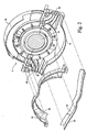
- FIG. 1 there is illustrated a turbine housing, generally designated 8 and including upper and lower turbine housing sections 10 and 12, respectively, joined along a horizontal midline 14 to one another and surrounding a rotor shaft 16.
- the upper and lower sections 10 and 12 extend axially unitarily in opposite axial directions and, in this illustrated embodiment, form part of a split flow axial steam turbine in which axially opposite stages of the turbine receive steam through annular axial passages or outlets 18.
- the upper and lower housing sections 10 and 12 define steam inlet ports 20 along opposite sides of the turbine housing 8.
- the inlet ports 20 receive high pressure steam from a high pressure section, not shown, for flow in a generally annular chamber 22 about the rotor 16.
- a portion 21 of the generally annular chamber 22 in the upper housing 10 is defined by an outer peripheral wall 24 and a pair of axially spaced side walls 26.
- Guide vanes 28 are provided in each of the inlet ports 20 for guiding the steam into the generally annular chamber 22.
- the portion of the generally annular chamber 22 in the lower housing 12 is defined by an outer peripheral wall 30 and a pair of side walls 32. It will be appreciated that with the steam inlet ports along opposite sides of the housing 8, the steam at each inlet port is divided for flow into the upper section 10 and into the lower section 12, i.e., into the upper and lower chamber portions 21 and 23, respectively.
- the steam flows generally in a circumferential direction and radially inwardly where it turns for flow axially through the axial outlets 18 into the first stages of the turbine.
- the chambers 21 and 23 in the upper and lower housings 10 and 12, respectively are divided into arcuate flow passages progressively of decreasing cross-sectional area from inlet ports 20 toward a medial location between the inlet ports and along the generally annular chamber.
- the chamber 21 in the upper housing 10 is divided into two arcuate flow paths, approximately 90° in circumferential length.
- the walls 22 defining the arcuate flow passage on opposite sides of the chamber portions converge toward one another in a direction away from the associated inlet port 20.
- the outer peripheral wall 24 extends from the inlet port 20 along a radially inwardly arcuate directed path to form a passage of decreasing cross-section, i.e., forms a pair of involutes.
- both the side walls 22 and the outer peripheral wall 24 converge toward one another and toward the axis, respectively, such that the flow area decreases linearly in cross-section from the inlet port affording a uniform mass flow and velocity in the upper chamber 21.
- a pair of such arcuate flow paths are provided in the upper housing 10 with the minimum cross-sectional area of the flow passages being defined at the juncture of the side walls and peripheral walls of each of the flow passages substantially medially between the inlet ports 20, e.g., at a vertical plane through the rotor axis.
- the arcuate passages in the lower housing 12 are somewhat shorter in circumferential length than the arcuate flow passages in the upper housing 10. These passages, however, also progressively decrease in constant cross-sectional area in a circumferential direction away from the inlet ports. The decrease in cross-sectional area is effected by extending the peripheral wall 30 progressively radially inwardly in a direction away from the inlet port to a location of minimum cross-sectional area substantially medially between the inlet ports, i.e., a pair of involutes are formed.
- the side walls defining the arcuate passages in the lower housing 10 may progressively converge toward one another in a circumferential direction away from the inlet port.
- the peripheral wall and side walls of the lower chamber defining the arcuate flow passages extend radially inwardly and converge, respectively, to define linearly decreasing cross-sectional area passages affording uniform mass flow and velocity about the lower section.
- the inlet design described above is in contrast to the constant cross-sectional annular area typically provided as the inlet for an axial flow steam turbine.
- the solid lines 34 represent the constant cross-sectional area of a prior art inlet
- the dashed lines 36 represent the decrease in cross-sectional area at a specified circumferential location about the generally annular inlet in accordance with a preferred embodiment of the present invention.
- the peripheral wall 24 represented by the dashed lines 36 forms an inwardly directed apex 38 substantially medially between the inlet ports 20 at the location of minimum cross-sectional area.
- the lower peripheral wall 30, represented by dashed lines 39 in Figure 5 forms an apex 40 substantially medially between the inlet ports 20.
- the mass flow and velocity may remain substantially constant at each circumferential location about the periphery of the rotor and hence the axial flow into the first stage(s) is substantially uniform and at constant velocity.
- the inlet hereof may be provided as part of original equipment or as a retrofit in existing steam turbines.
- the walls, both the side and peripheral walls defining the flow passages of decreasing cross-sectional area from the inlet ports toward their medial locations can be integrally formed within the housing sections 10 and 12 upon initial manufacture.
- the peripheral walls 24 and 30 need not be provided separately from the walls of the housings 10 and 12 but may be formed integrally, i.e., cast with the walls of housings 10 and 12. Where a retrofit is desired, the peripheral walls 24 and side walls 22 may be formed as unitary sections.
- a unitary section may comprise the side wall portions and the peripheral wall portion forming one of the upper quadrants of an arcuate flow passage of decreasing cross-section and installed as a unit into an existing steam turbine.
- a second section is then similarly installed in the upper housing 10 and the sections joined.
- one section comprised of walls 30 and 32 may be provided in the lower housing 12 or a pair of such unitary casings may be provided.
- the walls defining the arcuate flow passages of progressively decreasing cross-sectional area can be applied individually, for example, as individual steel plates, to the existing housing. This is illustrated in Figure 3 , wherein the individual steel plates for the side walls are designated 22.
- the peripheral walls 24 can be built up from individual plates and welded into the housings 10 and 12.
Landscapes
- Engineering & Computer Science (AREA)
- Mechanical Engineering (AREA)
- General Engineering & Computer Science (AREA)
- Turbine Rotor Nozzle Sealing (AREA)
Claims (10)
- Dampfeinlass für eine Dampfturbine, aufweisend:ein im Wesentlichen ringförmiges Gehäuse (10, 12) mit einer äußeren umgebenden Umfangswand und einem Paar axial beabstandeter Seitenwände (26), die sich nach innen erstrecken, um eine im Wesentlichen ringförmige Kammer (22) in dem Gehäuse und wenigstens einen im Wesentlichen ringförmigen Dampfauslass (18) im Wesentlichen in der Mitte des Gehäuses in Verbindung mit der Kammer zu definieren, um Dampf axial nach außen durch den Auslass in die erste Stufe der Turbine strömen zu lassen;ein Paar von Dampfeinlassöffnungen (20), die in Abstand voneinander um das Gehäuse herum zum Aufnehmen von Dampf und Überleiten des Dampfes in die Kammer angeordnet sind;wobei die Kammer (22) eine im Wesentlichen progressive Verringerung in der Querschnittsfläche im Wesentlichen in Umfangsrichtung weg von den Dampfeinlassöffnungen (20) hat, um eine im Wesentlichen gleichmäßige Dampfströmung um die Kammer (22) herum in einer im Wesentlichen radial nach innen gerichteten Richtung zu erzeugen, dadurch gekennzeichnet, dass die Außenumfangswand (24) einen nach innen gerichteten Scheitel (40) im Wesentlichen mittig zwischen den Einlassöffnungen (20) an einer Stelle einer minimalen Querschnittsfläche ausbildet.
- Dampfeinlass nach Anspruch 1, mit Führungsleitflügeln (28) in den Einlassöffnungen, um den Dampf von der Einlassöffnung aus in entgegengesetzte Richtungen um die Kammer herum zu führen.
- Dampfeinlass nach Anspruch 1 oder 2, wobei die Verringerung in der Querschnittsfläche für eine im Wesentlichen gleichmäßige radiale Einwärtsgeschwindigkeit des Dampfes um die Kammer herum sorgt.
- Dampfeinlass nach Anspruch 1 oder 2, wobei die Verringerung in der Querschnittsfläche für eine im Wesentlichen gleichmäßige axiale Strömung des Dampfes an dem axialen Auslass sorgt.
- Dampfeinlass nach einem der vorstehenden Ansprüche mit einem zweiten Dampfauslass (18) im Wesentlichen zentrisch in dem Gehäuse, um Dampf aus der Kammer in einer axialen Richtung entgegengesetzt zu der axialen Richtung des durch den ersten erwähnten Dampfauslass strömenden Dampfes strömen zu lassen.
- Dampfeinlass nach Anspruch 6, wobei die Verringerung in der Querschnittsfläche für eine im Wesentlichen gleichmäßige radiale Einwärtsgeschwindigkeit des Dampfes um die Kammer herum und eine im Wesentlichen gleichmäßige axiale Strömung an den Auslässen sorgt.
- Dampfeinlass nach einem der vorstehenden Ansprüche, wobei das ringförmige Gehäuse obere und untere Gehäuseabschnitte (10, 12) enthält, wobei jeder Abschnitt ein Paar bogenförmiger Strömungskanäle enthält, die in der Querschnittsfläche in einer Richtung von den entsprechenden Einlassöffnungen weg abnehmen und in einer minimalen Querschnittsfläche im Wesentlichen mittig zwischen den Einlassöffnungen enden.
- Verfahren zum Nachrüsten eines Dampfeinlasses, um eine im Wesentlichen gleichmäßige Geschwindigkeit von axial durch und um Dampfauslässe strömenden Dampf in einer Teilstrom-Axialdampfturbine zu erzielen, die ein Gehäuse mit einem Ringraum zum Aufnehmen von Dampf aus einem Paar in Umfangsrichtung in Abstand angeordneter Dampfeinlassöffnungen (20) und ein Paar axial in Abstand angeordneter Dampfauslässe (18) radial innerhalb des Ringraums hat, um Dampf aus dem Ringraum aufzunehmen und in entgegengesetzte axiale Richtungen zu Stufen der Turbine strömen zulassen, wobei das Verfahren die Schritte aufweist:Ausbilden mehrerer bogenförmiger Gehäuse (10, 12), wobei jedes eine Außenumfangswand (24, 30) und ein Paar axial in Abstand angeordneter Seitenwände (26, 32) hat, die sich von der Außenwand nach innen erstrecken, um einen im Wesentlichen bogenförmigen Dampfströmungskanal zum Verkleinern der Querschnittsfläche von einem Ende zu einem gegenüberliegenden Ende zu definieren, wobei die Außenumfangswand (24) einen Scheitel (40) im Wesentlichen mittig zwischen den Einlassöffnungen (20) an einer Stelle einer minimalen Querschnittsfläche ausbildet;Einbauen der Gehäuse als einteilige Gehäuse oder als diskrete Umfangswände und Seitenwände in dem Ringraum des Gehäuses mit ihren größeren Querschnittsenden in Verbindung mit den Einlassöffnungen und mit Kanälen in Verbindung mit den axialen Dampfauslässen, um Dampf mit einer im Wesentlichen gleichmäßigen Geschwindigkeit um die Auslässe in entgegengesetzte axiale Richtungen strömen zu lassen.
- Verfahren nach Anspruch 8 mit dem Schritt des Einbaus der Gehäuse in die Einhausung als einteiliges Gehäuse.
- Verfahren nach Anspruch 8 oder 9 mit dem Schritt des Einbaus der diskreten Wände in die Einhausung um die Gehäuse in der Einhausung ausbilden.
Applications Claiming Priority (2)
| Application Number | Priority Date | Filing Date | Title |
|---|---|---|---|
| US987695 | 2001-11-15 | ||
| US09/987,695 US6609881B2 (en) | 2001-11-15 | 2001-11-15 | Steam turbine inlet and methods of retrofitting |
Publications (3)
| Publication Number | Publication Date |
|---|---|
| EP1312759A2 EP1312759A2 (de) | 2003-05-21 |
| EP1312759A3 EP1312759A3 (de) | 2009-07-29 |
| EP1312759B1 true EP1312759B1 (de) | 2012-10-31 |
Family
ID=25533479
Family Applications (1)
| Application Number | Title | Priority Date | Filing Date |
|---|---|---|---|
| EP02257871A Expired - Lifetime EP1312759B1 (de) | 2001-11-15 | 2002-11-14 | Dampfturbineneinlass und Verfahren zum Nachrüsten eines Dampfturbineneinlasses |
Country Status (7)
| Country | Link |
|---|---|
| US (1) | US6609881B2 (de) |
| EP (1) | EP1312759B1 (de) |
| JP (1) | JP4341808B2 (de) |
| KR (1) | KR100909920B1 (de) |
| CN (1) | CN1330852C (de) |
| CZ (1) | CZ20023684A3 (de) |
| RU (1) | RU2302533C2 (de) |
Families Citing this family (27)
| Publication number | Priority date | Publication date | Assignee | Title |
|---|---|---|---|---|
| DE102004016172A1 (de) * | 2004-03-30 | 2005-10-20 | Bosch Gmbh Robert | Hand-Oberfräse |
| JP2008241579A (ja) * | 2007-03-28 | 2008-10-09 | Toshiba Corp | 原子力プラントの運転方法およびその運転装置 |
| JP4950118B2 (ja) * | 2008-05-08 | 2012-06-13 | 三菱重工業株式会社 | 蒸気タービンの蒸気インレット構造 |
| FR2937385B1 (fr) * | 2008-10-17 | 2010-12-10 | Turbomeca | Diffuseur muni d'aubes a orifices |
| DE102008062078B4 (de) * | 2008-12-16 | 2019-10-17 | Man Energy Solutions Se | Eintrittsstufe für eine Dampfturbine |
| EP2213922A1 (de) * | 2009-01-29 | 2010-08-04 | Siemens Aktiengesellschaft | Schnellschlussventil |
| CZ302698B6 (cs) * | 2009-05-19 | 2011-09-07 | Ceské vysoké ucení technické v Praze | Prechodový díl lopatkového stroje |
| EP2333253A1 (de) * | 2009-12-08 | 2011-06-15 | Siemens Aktiengesellschaft | Innengehäuse für eine Strömungsmaschine |
| EP3023593A1 (de) * | 2014-11-20 | 2016-05-25 | Siemens Aktiengesellschaft | Einströmungskontur für Einwellenanordnung |
| US9903225B2 (en) | 2015-03-09 | 2018-02-27 | Caterpillar Inc. | Turbocharger with low carbon steel shaft |
| US9879594B2 (en) | 2015-03-09 | 2018-01-30 | Caterpillar Inc. | Turbocharger turbine nozzle and containment structure |
| US9890788B2 (en) | 2015-03-09 | 2018-02-13 | Caterpillar Inc. | Turbocharger and method |
| US9638138B2 (en) | 2015-03-09 | 2017-05-02 | Caterpillar Inc. | Turbocharger and method |
| US9752536B2 (en) | 2015-03-09 | 2017-09-05 | Caterpillar Inc. | Turbocharger and method |
| US9915172B2 (en) | 2015-03-09 | 2018-03-13 | Caterpillar Inc. | Turbocharger with bearing piloted compressor wheel |
| US9732633B2 (en) | 2015-03-09 | 2017-08-15 | Caterpillar Inc. | Turbocharger turbine assembly |
| US9650913B2 (en) | 2015-03-09 | 2017-05-16 | Caterpillar Inc. | Turbocharger turbine containment structure |
| US9822700B2 (en) | 2015-03-09 | 2017-11-21 | Caterpillar Inc. | Turbocharger with oil containment arrangement |
| US9739238B2 (en) | 2015-03-09 | 2017-08-22 | Caterpillar Inc. | Turbocharger and method |
| US9683520B2 (en) | 2015-03-09 | 2017-06-20 | Caterpillar Inc. | Turbocharger and method |
| JP6491052B2 (ja) * | 2015-06-11 | 2019-03-27 | 三菱日立パワーシステムズ株式会社 | タービン入口構造、およびそれを用いた蒸気タービン |
| CN106401669A (zh) * | 2015-07-31 | 2017-02-15 | 新乡航空工业(集团)有限公司 | 一种中间级涡轮出口流道结构 |
| CN105134314A (zh) * | 2015-10-19 | 2015-12-09 | 东方电气集团东方汽轮机有限公司 | 一种带筒形内缸的汽轮机组高压部分结构 |
| US20180080324A1 (en) * | 2016-09-20 | 2018-03-22 | General Electric Company | Fluidically controlled steam turbine inlet scroll |
| CN111520195B (zh) * | 2020-04-03 | 2022-05-10 | 东方电气集团东方汽轮机有限公司 | 一种汽轮机低压进汽室导流结构及其参数设计方法 |
| CN113279825B (zh) * | 2021-06-11 | 2022-04-12 | 武汉大学 | 核电汽轮机全周进汽室设计方法及全周进汽室 |
| CN114508392B (zh) * | 2021-12-29 | 2023-07-18 | 东方电气集团东方汽轮机有限公司 | 一种汽轮机高压进汽室结构 |
Family Cites Families (22)
| Publication number | Priority date | Publication date | Assignee | Title |
|---|---|---|---|---|
| GB797780A (en) * | 1955-06-21 | 1958-07-09 | Daimler Benz Ag | Improvements relating to exhaust-gas turbines |
| US3038699A (en) * | 1958-11-04 | 1962-06-12 | Poly Ind Inc | Nozzle ring assembly |
| US3300180A (en) * | 1964-11-17 | 1967-01-24 | Worthington Corp | Segmented diaphragm assembly |
| NL139802B (nl) * | 1968-05-31 | 1973-09-17 | Stork Koninklijke Maschf | Turbine voor een compressibel medium. |
| DE2213071B2 (de) * | 1972-03-17 | 1975-05-28 | Kraftwerk Union Ag, 4330 Muelheim | Leitschaufelloser Leitkanal zur Drallerzeugung vor dem ersten Laufschaufelkranz von Turbinen |
| FR2229271A5 (en) * | 1973-05-07 | 1974-12-06 | Kraftwerk Union Ag | Device for rotating steam in axial-flow turbine - has narrowing tangential nozzles leading to annular around rotor |
| DE2435153B2 (de) * | 1974-07-22 | 1977-06-30 | Kraftwerk Union AG, 4330 Mülheim | Turbomaschine, insbesondere dampfturbine mit hoher dampfeintrittstemperatur |
| CH579212A5 (de) * | 1974-12-16 | 1976-08-31 | Bbc Brown Boveri & Cie | |
| US4025229A (en) * | 1975-11-14 | 1977-05-24 | Turbodyne Corporation (Steam Turbine Div.) | Diaphragm with cast nozzle blocks and method of construction thereof |
| GB1550932A (en) * | 1976-04-15 | 1979-08-22 | Forster T O | Nozzle insert for a turbine |
| SU1481444A1 (ru) * | 1983-10-17 | 1989-05-23 | Производственное Объединение Турбостроения "Ленинградский Металлический Завод" | Цилиндр паровой турбины |
| SU1495443A1 (ru) * | 1986-09-15 | 1989-07-23 | Брянский Институт Транспортного Машиностроения | Цилиндр паровой турбины |
| SU1625988A1 (ru) * | 1987-02-02 | 1991-02-07 | Всесоюзный научно-исследовательский и конструкторско-технологический институт компрессорного машиностроения | Входное устройство турбомашины |
| CH676735A5 (de) * | 1988-08-03 | 1991-02-28 | Asea Brown Boveri | |
| DE4100777A1 (de) * | 1990-12-18 | 1992-06-25 | Asea Brown Boveri | Einlassgehaeuse fuer dampfturbine |
| US5593273A (en) | 1994-03-28 | 1997-01-14 | General Electric Co. | Double flow turbine with axial adjustment and replaceable steam paths and methods of assembly |
| JPH08260903A (ja) * | 1995-03-28 | 1996-10-08 | Toshiba Corp | 蒸気タービンの再熱蒸気室 |
| US5601405A (en) * | 1995-08-14 | 1997-02-11 | Coates; George J. | Valve apparatus for steam turbines |
| US5927943A (en) * | 1997-09-05 | 1999-07-27 | Dresser-Rand Company | Inlet casing for a turbine |
| JPH11303642A (ja) * | 1998-04-24 | 1999-11-02 | Ishikawajima Harima Heavy Ind Co Ltd | 過給機 |
| US6386829B1 (en) * | 1999-07-02 | 2002-05-14 | Power Technology, Incorporated | Multi-valve arc inlet for steam turbine |
| JP4370661B2 (ja) * | 2000-03-17 | 2009-11-25 | アイシン精機株式会社 | 可変容量ターボチャージャ |
-
2001
- 2001-11-15 US US09/987,695 patent/US6609881B2/en not_active Expired - Lifetime
-
2002
- 2002-11-07 CZ CZ20023684A patent/CZ20023684A3/cs unknown
- 2002-11-14 JP JP2002330340A patent/JP4341808B2/ja not_active Expired - Fee Related
- 2002-11-14 EP EP02257871A patent/EP1312759B1/de not_active Expired - Lifetime
- 2002-11-14 KR KR1020020070677A patent/KR100909920B1/ko not_active Expired - Fee Related
- 2002-11-14 RU RU2002130584/06A patent/RU2302533C2/ru not_active IP Right Cessation
- 2002-11-15 CN CNB021513015A patent/CN1330852C/zh not_active Expired - Fee Related
Also Published As
| Publication number | Publication date |
|---|---|
| EP1312759A3 (de) | 2009-07-29 |
| KR100909920B1 (ko) | 2009-07-29 |
| RU2302533C2 (ru) | 2007-07-10 |
| CN1330852C (zh) | 2007-08-08 |
| EP1312759A2 (de) | 2003-05-21 |
| CN1420257A (zh) | 2003-05-28 |
| US20030091431A1 (en) | 2003-05-15 |
| US6609881B2 (en) | 2003-08-26 |
| JP4341808B2 (ja) | 2009-10-14 |
| KR20030040166A (ko) | 2003-05-22 |
| CZ20023684A3 (cs) | 2003-12-17 |
| JP2003193809A (ja) | 2003-07-09 |
Similar Documents
| Publication | Publication Date | Title |
|---|---|---|
| US6609881B2 (en) | Steam turbine inlet and methods of retrofitting | |
| EP1422382B1 (de) | Axialdurchströmte turbine | |
| EP2402618B1 (de) | Sauggehäuse und strömungsmaschine | |
| RU2002130584A (ru) | Впускное отверстие паровой турбины и способ его модификации | |
| WO2014143413A2 (en) | Seal assembly including grooves in a radially outwardly facing side of a platform in a gas turbine engine | |
| EP2821651B1 (de) | Rotationsmaschine | |
| US5953919A (en) | Combustion chamber having integrated guide blades | |
| US6332754B1 (en) | Steam turbine | |
| EP2604801B1 (de) | Leitschaufelring und montageverfahren | |
| EP3094822B1 (de) | Schaufel für eine gasturbine und verfahren zur herstellung einer solchen schaufel | |
| JP2015078662A (ja) | 圧縮機、及びガスタービン | |
| US7828514B2 (en) | Rotor for an engine | |
| JP2019100342A (ja) | 遠心圧縮機 | |
| US8286430B2 (en) | Steam turbine two flow low pressure configuration | |
| US8545170B2 (en) | Turbo machine efficiency equalizer system | |
| CA1145263A (en) | Turbine blade rotor | |
| EP3296514B1 (de) | Fluidisch gesteuerte dampfturbineneinlassspirale | |
| EP0416948B1 (de) | Einstellbarer radialer Düsenring für Turbinen | |
| US7713023B2 (en) | Steam turbine nozzle box and methods of fabricating | |
| EP3412872B1 (de) | Statoranordnung für eine radial-axial expansionsstufe einer dampfturbine | |
| AU749624B2 (en) | A method for fabricating a turbine inlet casing and the turbine inlet casing | |
| EP3960999B1 (de) | Gasturbine und verfahren zur herstellung einer gasturbine | |
| EP4015770B1 (de) | Gasturbinentriebwerk mit lagergehäusedeckel | |
| CN112639293B (zh) | 具有至少一个盖的涡轮机壳体、涡轮机、用于制造盖的方法 | |
| PL179810B1 (pl) | Maszyna wirnikowa z przeplywem osiowym PL |
Legal Events
| Date | Code | Title | Description |
|---|---|---|---|
| PUAI | Public reference made under article 153(3) epc to a published international application that has entered the european phase |
Free format text: ORIGINAL CODE: 0009012 |
|
| AK | Designated contracting states |
Designated state(s): AT BE BG CH CY CZ DE DK EE ES FI FR GB GR IE IT LI LU MC NL PT SE SK TR |
|
| AX | Request for extension of the european patent |
Extension state: AL LT LV MK RO SI |
|
| RIN1 | Information on inventor provided before grant (corrected) |
Inventor name: BROWN, DANIEL MARK Inventor name: MATTICE, RICHARD LLOYD Inventor name: HUNTER, ANDREW IVAN CHRISTOPHER Inventor name: KIRBY, GEORGE HORNER Inventor name: THOMPSON, BRIAN E. |
|
| PUAL | Search report despatched |
Free format text: ORIGINAL CODE: 0009013 |
|
| AK | Designated contracting states |
Kind code of ref document: A3 Designated state(s): AT BE BG CH CY CZ DE DK EE ES FI FR GB GR IE IT LI LU MC NL PT SE SK TR |
|
| AX | Request for extension of the european patent |
Extension state: AL LT LV MK RO SI |
|
| 17P | Request for examination filed |
Effective date: 20100129 |
|
| AKX | Designation fees paid |
Designated state(s): CH DE FR IT LI |
|
| 17Q | First examination report despatched |
Effective date: 20100805 |
|
| GRAP | Despatch of communication of intention to grant a patent |
Free format text: ORIGINAL CODE: EPIDOSNIGR1 |
|
| GRAS | Grant fee paid |
Free format text: ORIGINAL CODE: EPIDOSNIGR3 |
|
| GRAA | (expected) grant |
Free format text: ORIGINAL CODE: 0009210 |
|
| AK | Designated contracting states |
Kind code of ref document: B1 Designated state(s): CH DE FR IT LI |
|
| REG | Reference to a national code |
Ref country code: CH Ref legal event code: EP |
|
| REG | Reference to a national code |
Ref country code: CH Ref legal event code: NV Representative=s name: SERVOPATENT GMBH, CH |
|
| REG | Reference to a national code |
Ref country code: DE Ref legal event code: R096 Ref document number: 60243945 Country of ref document: DE Effective date: 20121227 |
|
| PLBE | No opposition filed within time limit |
Free format text: ORIGINAL CODE: 0009261 |
|
| STAA | Information on the status of an ep patent application or granted ep patent |
Free format text: STATUS: NO OPPOSITION FILED WITHIN TIME LIMIT |
|
| 26N | No opposition filed |
Effective date: 20130801 |
|
| REG | Reference to a national code |
Ref country code: DE Ref legal event code: R097 Ref document number: 60243945 Country of ref document: DE Effective date: 20130801 |
|
| REG | Reference to a national code |
Ref country code: FR Ref legal event code: PLFP Year of fee payment: 14 |
|
| REG | Reference to a national code |
Ref country code: FR Ref legal event code: PLFP Year of fee payment: 15 |
|
| PGFP | Annual fee paid to national office [announced via postgrant information from national office to epo] |
Ref country code: DE Payment date: 20161123 Year of fee payment: 15 Ref country code: CH Payment date: 20161128 Year of fee payment: 15 Ref country code: FR Payment date: 20161123 Year of fee payment: 15 |
|
| PGFP | Annual fee paid to national office [announced via postgrant information from national office to epo] |
Ref country code: IT Payment date: 20161124 Year of fee payment: 15 |
|
| REG | Reference to a national code |
Ref country code: DE Ref legal event code: R119 Ref document number: 60243945 Country of ref document: DE |
|
| PG25 | Lapsed in a contracting state [announced via postgrant information from national office to epo] |
Ref country code: LI Free format text: LAPSE BECAUSE OF NON-PAYMENT OF DUE FEES Effective date: 20171130 Ref country code: CH Free format text: LAPSE BECAUSE OF NON-PAYMENT OF DUE FEES Effective date: 20171130 |
|
| REG | Reference to a national code |
Ref country code: FR Ref legal event code: ST Effective date: 20180731 |
|
| PG25 | Lapsed in a contracting state [announced via postgrant information from national office to epo] |
Ref country code: FR Free format text: LAPSE BECAUSE OF NON-PAYMENT OF DUE FEES Effective date: 20171130 Ref country code: IT Free format text: LAPSE BECAUSE OF NON-PAYMENT OF DUE FEES Effective date: 20171114 Ref country code: DE Free format text: LAPSE BECAUSE OF NON-PAYMENT OF DUE FEES Effective date: 20180602 |