EP4015770B1 - Gasturbinentriebwerk mit lagergehäusedeckel - Google Patents
Gasturbinentriebwerk mit lagergehäusedeckel Download PDFInfo
- Publication number
- EP4015770B1 EP4015770B1 EP21215928.9A EP21215928A EP4015770B1 EP 4015770 B1 EP4015770 B1 EP 4015770B1 EP 21215928 A EP21215928 A EP 21215928A EP 4015770 B1 EP4015770 B1 EP 4015770B1
- Authority
- EP
- European Patent Office
- Prior art keywords
- bearing housing
- gas turbine
- baffle
- turbine engine
- impeller
- Prior art date
- Legal status (The legal status is an assumption and is not a legal conclusion. Google has not performed a legal analysis and makes no representation as to the accuracy of the status listed.)
- Active
Links
Images




Classifications
-
- F—MECHANICAL ENGINEERING; LIGHTING; HEATING; WEAPONS; BLASTING
- F01—MACHINES OR ENGINES IN GENERAL; ENGINE PLANTS IN GENERAL; STEAM ENGINES
- F01D—NON-POSITIVE DISPLACEMENT MACHINES OR ENGINES, e.g. STEAM TURBINES
- F01D5/00—Blades; Blade-carrying members; Heating, heat-insulating, cooling or antivibration means on the blades or the members
- F01D5/02—Blade-carrying members, e.g. rotors
- F01D5/04—Blade-carrying members, e.g. rotors for radial-flow machines or engines
- F01D5/043—Blade-carrying members, e.g. rotors for radial-flow machines or engines of the axial inlet- radial outlet, or vice versa, type
- F01D5/046—Heating, heat insulation or cooling means
-
- F—MECHANICAL ENGINEERING; LIGHTING; HEATING; WEAPONS; BLASTING
- F01—MACHINES OR ENGINES IN GENERAL; ENGINE PLANTS IN GENERAL; STEAM ENGINES
- F01D—NON-POSITIVE DISPLACEMENT MACHINES OR ENGINES, e.g. STEAM TURBINES
- F01D25/00—Component parts, details, or accessories, not provided for in, or of interest apart from, other groups
- F01D25/08—Cooling; Heating; Heat-insulation
- F01D25/12—Cooling
- F01D25/125—Cooling of bearings
-
- F—MECHANICAL ENGINEERING; LIGHTING; HEATING; WEAPONS; BLASTING
- F01—MACHINES OR ENGINES IN GENERAL; ENGINE PLANTS IN GENERAL; STEAM ENGINES
- F01D—NON-POSITIVE DISPLACEMENT MACHINES OR ENGINES, e.g. STEAM TURBINES
- F01D25/00—Component parts, details, or accessories, not provided for in, or of interest apart from, other groups
- F01D25/16—Arrangement of bearings; Supporting or mounting bearings in casings
-
- F—MECHANICAL ENGINEERING; LIGHTING; HEATING; WEAPONS; BLASTING
- F16—ENGINEERING ELEMENTS AND UNITS; GENERAL MEASURES FOR PRODUCING AND MAINTAINING EFFECTIVE FUNCTIONING OF MACHINES OR INSTALLATIONS; THERMAL INSULATION IN GENERAL
- F16C—SHAFTS; FLEXIBLE SHAFTS; ELEMENTS OR CRANKSHAFT MECHANISMS; ROTARY BODIES OTHER THAN GEARING ELEMENTS; BEARINGS
- F16C35/00—Rigid support of bearing units; Housings, e.g. caps, covers
- F16C35/04—Rigid support of bearing units; Housings, e.g. caps, covers in the case of ball or roller bearings
- F16C35/042—Housings for rolling element bearings for rotary movement
-
- F—MECHANICAL ENGINEERING; LIGHTING; HEATING; WEAPONS; BLASTING
- F16—ENGINEERING ELEMENTS AND UNITS; GENERAL MEASURES FOR PRODUCING AND MAINTAINING EFFECTIVE FUNCTIONING OF MACHINES OR INSTALLATIONS; THERMAL INSULATION IN GENERAL
- F16C—SHAFTS; FLEXIBLE SHAFTS; ELEMENTS OR CRANKSHAFT MECHANISMS; ROTARY BODIES OTHER THAN GEARING ELEMENTS; BEARINGS
- F16C37/00—Cooling of bearings
- F16C37/007—Cooling of bearings of rolling bearings
-
- F—MECHANICAL ENGINEERING; LIGHTING; HEATING; WEAPONS; BLASTING
- F01—MACHINES OR ENGINES IN GENERAL; ENGINE PLANTS IN GENERAL; STEAM ENGINES
- F01D—NON-POSITIVE DISPLACEMENT MACHINES OR ENGINES, e.g. STEAM TURBINES
- F01D11/00—Preventing or minimising internal leakage of working-fluid, e.g. between stages
- F01D11/02—Preventing or minimising internal leakage of working-fluid, e.g. between stages by non-contact sealings, e.g. of labyrinth type
- F01D11/04—Preventing or minimising internal leakage of working-fluid, e.g. between stages by non-contact sealings, e.g. of labyrinth type using sealing fluid, e.g. steam
-
- F—MECHANICAL ENGINEERING; LIGHTING; HEATING; WEAPONS; BLASTING
- F01—MACHINES OR ENGINES IN GENERAL; ENGINE PLANTS IN GENERAL; STEAM ENGINES
- F01D—NON-POSITIVE DISPLACEMENT MACHINES OR ENGINES, e.g. STEAM TURBINES
- F01D25/00—Component parts, details, or accessories, not provided for in, or of interest apart from, other groups
- F01D25/16—Arrangement of bearings; Supporting or mounting bearings in casings
- F01D25/162—Bearing supports
-
- F—MECHANICAL ENGINEERING; LIGHTING; HEATING; WEAPONS; BLASTING
- F05—INDEXING SCHEMES RELATING TO ENGINES OR PUMPS IN VARIOUS SUBCLASSES OF CLASSES F01-F04
- F05D—INDEXING SCHEME FOR ASPECTS RELATING TO NON-POSITIVE-DISPLACEMENT MACHINES OR ENGINES, GAS-TURBINES OR JET-PROPULSION PLANTS
- F05D2210/00—Working fluids
- F05D2210/40—Flow geometry or direction
- F05D2210/42—Axial inlet and radial outlet
-
- F—MECHANICAL ENGINEERING; LIGHTING; HEATING; WEAPONS; BLASTING
- F05—INDEXING SCHEMES RELATING TO ENGINES OR PUMPS IN VARIOUS SUBCLASSES OF CLASSES F01-F04
- F05D—INDEXING SCHEME FOR ASPECTS RELATING TO NON-POSITIVE-DISPLACEMENT MACHINES OR ENGINES, GAS-TURBINES OR JET-PROPULSION PLANTS
- F05D2230/00—Manufacture
- F05D2230/50—Building or constructing in particular ways
- F05D2230/53—Building or constructing in particular ways by integrally manufacturing a component, e.g. by milling from a billet or one piece construction
-
- F—MECHANICAL ENGINEERING; LIGHTING; HEATING; WEAPONS; BLASTING
- F05—INDEXING SCHEMES RELATING TO ENGINES OR PUMPS IN VARIOUS SUBCLASSES OF CLASSES F01-F04
- F05D—INDEXING SCHEME FOR ASPECTS RELATING TO NON-POSITIVE-DISPLACEMENT MACHINES OR ENGINES, GAS-TURBINES OR JET-PROPULSION PLANTS
- F05D2240/00—Components
- F05D2240/10—Stators
- F05D2240/12—Fluid guiding means, e.g. vanes
- F05D2240/126—Baffles or ribs
-
- F—MECHANICAL ENGINEERING; LIGHTING; HEATING; WEAPONS; BLASTING
- F05—INDEXING SCHEMES RELATING TO ENGINES OR PUMPS IN VARIOUS SUBCLASSES OF CLASSES F01-F04
- F05D—INDEXING SCHEME FOR ASPECTS RELATING TO NON-POSITIVE-DISPLACEMENT MACHINES OR ENGINES, GAS-TURBINES OR JET-PROPULSION PLANTS
- F05D2240/00—Components
- F05D2240/10—Stators
- F05D2240/14—Casings or housings protecting or supporting assemblies within
-
- F—MECHANICAL ENGINEERING; LIGHTING; HEATING; WEAPONS; BLASTING
- F05—INDEXING SCHEMES RELATING TO ENGINES OR PUMPS IN VARIOUS SUBCLASSES OF CLASSES F01-F04
- F05D—INDEXING SCHEME FOR ASPECTS RELATING TO NON-POSITIVE-DISPLACEMENT MACHINES OR ENGINES, GAS-TURBINES OR JET-PROPULSION PLANTS
- F05D2240/00—Components
- F05D2240/50—Bearings
-
- F—MECHANICAL ENGINEERING; LIGHTING; HEATING; WEAPONS; BLASTING
- F16—ENGINEERING ELEMENTS AND UNITS; GENERAL MEASURES FOR PRODUCING AND MAINTAINING EFFECTIVE FUNCTIONING OF MACHINES OR INSTALLATIONS; THERMAL INSULATION IN GENERAL
- F16C—SHAFTS; FLEXIBLE SHAFTS; ELEMENTS OR CRANKSHAFT MECHANISMS; ROTARY BODIES OTHER THAN GEARING ELEMENTS; BEARINGS
- F16C2360/00—Engines or pumps
- F16C2360/23—Gas turbine engines
Definitions
- the invention relates generally to gas turbine engines and, more particularly, to gas turbine engines having a centrifugal compressor with an impeller.
- the invention further relates to a method of manufacturing the gas turbine engine.
- Centrifugal compressors in a gas turbine engine include an impeller and a diffuser downstream from the impeller. At the compressor exit, the compressed air may be used, in addition to providing compressor air to the engine core for combustion, to pressurize an engine air system as well as pressurize nearby air-oil interfaces such as those sealing bearing cavities.
- an impeller baffle is disposed downstream of a rear face of the impeller, to limit losses and restrict air which may otherwise escape around the rear face of the impeller.
- Such impeller baffles are typically add-on parts that require some form of attachment to a mating part. These add-on baffles may be complicated to assemble, afford minimal dynamic tuning options, and their attachment means may loosen or require service over time.
- US 5 415 478 A discloses a prior art gas turbine engine according to the preamble of claim 1.
- DE 196 52 754 discloses a turbocharger comprising a centrifugal compressor having an impeller, a bearing casing including bearings rotationally supporting the impeller, and an intermediate wall separating the compressor casing from the bearing casing, the intermediate wall comprising a plurality of stiffening elements.
- US 2005/235651 A1 discloses a gas turbine engine comprising a centrifugal compressor having an impeller and a lubrication sump that includes sump walls that define a bearing compartment in which a bearing is located. Hot compressor discharge air flows radially inward along the backface of the impeller and through a high pressure cavity of the lubrication sump.
- the front baffle face is shaped to follow the profile of the rear face of the impeller.
- the plurality of stiffening elements include one or more of ribs, webs or struts.
- the plurality of stiffening elements are hollow.
- the plurality of stiffening elements are evenly spaced about the circumference of the annular collar.
- the baffle includes a varying thickness between the front baffle face and the rear baffle face.
- the thickness of the baffle varies in a radial or circumferential direction.
- the plurality of air passages are in fluid communication with an interior chamber of the bearing housing.
- the flange includes a plurality of bolt holes for mounting to the exterior surface of the bearing housing.
- the bearing housing cover is mounted to an upstream end of the bearing housing.
- the gas turbine engine further includes a second bearing housing cover mounted to a downstream end of the bearing housing, the second bearing housing cover including a plurality of air passages in fluid communication with the plurality of air passages in the bearing housing cover mounted to the upstream end of the bearing housing.
- the central baffle opening in the bearing housing cover includes an inner ring having a lip extending radially inwardly adjacent an outer surface of the bearing housing to define an air gap leading to the interior chamber of the bearing housing.
- FIG. 1 illustrates an exemplary gas turbine engine 10 of a type preferably provided for use in subsonic flight, generally comprising in serial flow communication a fan 12 through which ambient air is propelled, a centrifugal compressor 14 for pressurizing the air, a combustor 16 in which the compressed air is mixed with fuel and ignited for generating an annular stream of hot combustion gases, and a turbine 18 for extracting energy from the combustion gases.
- a main engine shaft 20 along longitudinal axis 11 interconnects the fan 12, the centrifugal compressor 14 and the turbine 18.
- pressurized air provided by the centrifugal compressor 14 through a diffuser 22 enters the combustor 16 for combustion.
- FIG. 1 shows gas turbine engine 10 to be a turbofan gas turbine engine, it is understood that the present disclosure is applicable to other types of gas turbine engines as well.
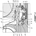
- FIG. 2 shows an enhanced view of the engine 10 proximate the combustor 16 and diffuser 22.
- a centrifugal compressor 14 as in FIG. 1 which may include multiple axial stage rotors, is followed by an impeller 24 and a coverplate 26.
- the centrifugal compressor 14 supplies pressurized air to the combustor 16, the hot gases from which drive a turbine 18 as in FIG. 1 .
- the impeller 24 has a rear face 28 behind which the air swirls at high velocity due to the rotation of the impeller 24. This swirling, high-velocity air tends to lower the pressure of the "rear face air", i.e. the airflow F immediately behind (i.e. downstream of) the impeller rear face 28.
- a bearing housing 30, located downstream from the impeller 24, houses a bearing 32 which rotationally supports the main engine shaft 20, upon which the centrifugal compressor 14 and turbine 18 are mounted for example.
- the bearing 32 housed within an interior chamber of the bearing housing 30, is lubricated and cooled with oil circulated by a lubrication system within the gas turbine engine 10.
- a front carbon seal 34 as well as a rear carbon seal 36 are mounted to the bearing housing 30 to ensure that oil is sealed within the bearing housing 30.
- the front carbon seal 34 which may be a controlled-gap seal, is pressurized to prevent oil from leaking out of the bearing housing 30. Other seals may be contemplated as well.
- a bearing housing cover 38 mountable to the bearing housing 30 includes an integrated impeller baffle 40.
- integrated it is understood that the impeller baffle 40 is machined or otherwise formed as a single, unitary or monolithic, piece with the bearing housing cover 38.
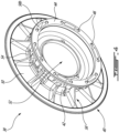
- the bearing housing cover 38 includes an annular collar 42 having a flange 44 mountable to an exterior surface of the bearing housing 30. When mounted, the cover 38 at least partially encloses the bearing housing 30 and aids in sealing oil within the bearing housing 30.
- the flange 44 includes a plurality of holes 46 arranged in a bolt pattern for mounting to the bearing housing 30, illustratively twelve holes 46 about the perimeter of the flange 44.
- the width of the flange 44 may vary, for instance based on the structural requirements of the cover 38 or the sizing of the exterior surface of the bearing housing 30. The mounting or fastening of the bearing housing cover 38 to the bearing housing 30 will be discussed in further detail below.
- the impeller baffle 40 is integrally formed with the annular collar 42 and includes a generally annular body with a front baffle face 48, a rear baffle face 50 and a central baffle opening 52.
- a rounded bevel edge 54 joins the annular collar 42 to the rear baffle face 50, although other transition structures may be contemplated as well.
- the impeller baffle 40 may be manufactured to have a complex profile shape based on the engine's 10 particular air system requirements.
- the front baffle face 48 may have a profile that follows that of the impeller rear face 28.
- Other shapes or profiles for the impeller baffle 40 may be contemplated as well.
- stiffening elements 56 extend from the rear baffle face 50 to the annular collar 42.
- the stiffening elements 56 also referred to as reinforcement elements, may be integral with the bearing housing cover 38, i.e. formed from a single piece. In other cases, additional add-on or mountable reinforcement elements may be contemplated as well. In the embodiment shown in FIG. 3B , these stiffening elements 56 are in the form of webs. Other types of stiffening elements may be contemplated as well, as will be discussed in further detail below.
- the web base 56a provides support for the web 56 at the rear baffle face 50.
- the web body 56b is shown to be thinner than the web base 56a and slightly curved, although other shapes and sizes may be contemplated as well.
- the web end 56c where the web 56 meets the annular collar 42 is reinforced for added support.
- the number, thickness and spacing of the stiffening elements 56 may vary, for instance based on the structural requirements of the engine 10. For instance, while the webs 56 shown in FIG. 3B are spaced equally from one another, in other cases the spacing between the webs 56 (or other stiffening elements) may vary along the circumference of the bearing housing cover 38.
- various parameters of the stiffening elements 56 can be adjusted to vary or tune the dynamic response of the impeller baffle 40 to reduce vibrations, as will be discussed in further detail below.
- a plurality of air passages 58 extend through the bearing housing cover 38.
- the bearing housing cover 38 includes six air passages 58, five of which are visible in FIG. 3A .
- Three of the six air passages 58 extend at least partially axially through the annular collar 42 between air inlets 58a disposed on the front baffle face 48 and air outlets 58b disposed on the flange 44.
- the remaining three air passages 58 (two of which are visible in FIG. 3A ) have air inlets 58a within the annular collar 42 and outlets 58b disposed on the flange 44.
- the six air outlets 58b are disposed on the flange 44.
- Other numbers and pathways for the air passages 58 may be contemplated as well.
- the air passages 58 may divert a portion of the airflow F from the impeller rear face 28 to the bearing housing 30 and/or to components downstream of the bearing housing 30 for various engine cooling and sealing requirements.
- the number of inlets 58a corresponds to the number of outlets 58b.
- the inlets 58a and outlets 58b are slot-like openings disposed about the circumference of the central baffle opening on the front baffle face 48, within the annular collar 42 or on the flange 44.
- Other shapes, positions and sizes of inlets 58a and/or outlets 58b may be contemplated as well, for instance based on the airflow and/or sealing requirements of the various components of the bearing housing 30.
- the bearing housing cover 38 is mountable to the bearing housing 30 at an upstream end thereof.
- the bearing housing cover 38 may also be referred to as the front bearing housing cover 38, while a rear bearing housing cover 60 is mountable to a downstream end of the bearing housing 30.
- a plurality of bolts 62 or other like fasteners may be used to fasten the bearing housing covers 38, 60 to the bearing housing 30.
- each bolt 62 may pass through a bolt hole 46 on the flange 44 of the front bearing housing cover 38, through a bore 64 in the bearing housing 30 and then through a corresponding bolt hole (not shown) in the rear bearing housing cover 60.
- the bolt holes 46 in front bearing housing cover 38 and/or the bolt holes in the rear bearing housing cover 60 may be threaded for secure attachment.
- the bore 64 may be threaded as well. Other forms of attachment may be contemplated as well.
- the rear bearing housing cover 60 includes a plurality of air passages 66.
- air passageways in fluid communication with the air passages 58, 66, for instances the bores 64 allow airflow F to flow between air passages 58 in the front bearing housing cover 38 and the air passages 66 in the rear bearing housing cover 60.
- air may pass through hollow portions of the bolts 62 themselves, and/or around the bolts 62 within the bores 64.
- the airflow F can be diverted to various components downstream of the bearing housing 30 for cooling and/or sealing purposes.
- the dimensions of the air passages 58, 66 may vary, for instance based on the cooling and/or sealing needs of these various components.
- the bearing housing cover 38 further includes an inner ring 68 and a lip 70 to control the incoming air entering the bearing housing 30.
- the width of the inner ring 68 may vary to alter the size of the central baffle opening 52, for instance in response to engine requirements for temperature and pressure gradients.
- the lip 70 extends radially inwardly into close proximity with an outer surface of a runner 72 supporting the front carbon seal 34 to thus define a narrow air gap 74 through which the airflow F may enter the bearing housing 30.
- the inner diameter of the lip 70 may be coated for a labyrinth seal with the runner 72. In some cases, the airflow F entering through the narrow gap 74 may aid in sealing the front carbon seal 34.
- the downstream end of the bearing housing 30 may similarly include a narrow air gap 74 formed by an outer surface of a runner 72.
- Airflow F may thus be provided to the downstream end of the bearing housing 30, for instance to aid in sealing the rear carbon seal 36. This airflow F may be diverted from the exit of the air passages in the rear bearing housing cover 60, although other airflow sources may be contemplated as well.
- the thickness of the baffle 40 i.e. between the front baffle face 48 and the rear baffle face 50, can vary. For instance, larger engines with different dynamic responses may require a thicker baffle 40 to ensure structural integrity. Alternatively, in smaller engines, a thinner baffle 40 may be used to reduce the overall weight of the engine 10. In certain cases, the thickness of baffle 40 may vary, for instance in radial or circumferential directions. For instance, the baffle 40 may be thinner at the circumferential positions where the stiffening elements 56 meet the rear baffle face 50. In addition, the baffle 40 may be thicker at other circumferential positions to provide additional structure where necessary.
- the baffle 40 may be thicker towards the central baffle opening 52 and become thinner towards the radial outer edge of the baffle 40.
- the reverse configuration may be contemplated as well.
- the thickness of the baffle 40 may also vary based on the dynamic tuning requirements of the baffle 40, as will be discussed in further detail below.
- the stiffening elements 56' may have shapes or sizes that vary from one to the other.
- each alternating web 56' terminates at a different height on the annular collar 42, alternating between reaching midway up the annular collar 42 and reaching a point just below the flange 44.
- Such variations in height may, for instance, aid in reducing the weight of the bearing housing cover 38, provide additional rigidity in strategic locations, and/or aid in dynamically tuning the baffle 40.
- the webs 56' shown in FIG. 4 are thicker than those in FIG. 3B , for instance for added strength.
- the stiffening elements 56" are in the form of ribs 56" extending from the rear baffle face 50 to the annular collar 42.
- the number, spacing and thickness of the ribs 56" may vary, for instance based on structural and/or weight requirements.
- the positioning of the ends of the ribs 56" on the rear baffle face 50 and/or on the annular collar 42 may vary as well.
- the ribs 56" may be hollow, for instance to save weight, while in other cases they may be solid for added rigidity. Combinations of hollow and solid ribs 56", for instance in alternating order, may be contemplated as well.
- the bearing housing cover 38 with the integrated impeller baffle 40 is manufactured or otherwise formed from a single piece of material.
- Various manufacturing techniques may be contemplated, such as machining from a solid material, casting, or other suitable techniques.
- machining from a solid material, casting, or other suitable techniques there are fewer required manufacturing steps, as the baffle does not need to be stamped and then welded or brazed to the bearing housing.
- part tolerances between the baffle 40 and bearing housing cover 38 may be improved relative to non-integrated impeller baffles as the two parts are integrated.
- the herein described impeller baffle 40 may be easier to mount or assemble to the bearing housing than non-integrated baffles due to its integration in the bearing housing cover 38, and the reduced part count may reduce the required assembly time.
- the integrated impeller baffle 40 of the bearing housing cover 38 may be dynamically tuned. As the baffle's 40 natural frequencies are typically within running range of the engine 10, such dynamic tuning may be done to prevent undesirable vibrations. As the bearing housing cover 38 with the integrated impeller baffle 40 is manufactured from a single part, there may be an opportunity during the design process to tune the baffle's 40 dynamic response to avoid unwanted natural frequencies. As discussed above, such tuning may be done by optimizing the stiffening elements 56, for instance by altering the type, spacing, and number of stiffening elements 56. Such tuning may also be done by varying the thickness of the baffle 40. Other dynamic tuning methods may be contemplated as well.
Landscapes
- Engineering & Computer Science (AREA)
- General Engineering & Computer Science (AREA)
- Mechanical Engineering (AREA)
- Structures Of Non-Positive Displacement Pumps (AREA)
- Supercharger (AREA)
Claims (13)
- Gasturbinentriebwerk (10), umfassend:einen Radialverdichter, (14) der ein Laufrad (24) aufweist;ein Lagergehäuse (30), das sich stromabwärts des Laufrads (24) befindet, wobei das Lagergehäuse (30) ein Lager (32) innerhalb einer Innenkammer beinhaltet, wobei das Lager (32) das Laufrad (24) drehbar lagert; undeinen Lagergehäusedeckel (38), umfassend:einen ringförmigen Kragen (42), der einen Flansch (44) aufweist, der an einer Außenfläche des Lagergehäuses (30) montierbar ist; undeine Laufrad-Trennwand (40), die integral mit dem ringförmigen Kragen (42) ausgebildet ist, wobei die Laufrad-Trennwand (40) einen ringförmigen Körper mit einer vorderen Trennwandfläche (48), die benachbart zu einer Rückseite (28) des Laufrads (24) positionierbar ist, einer hinteren Trennwandfläche (50) und einer zentralen Trennwandöffnung (52) aufweist;dadurch gekennzeichnet, dassdie hintere Trennwandfläche (50) eine Vielzahl von Versteifungselementen (56, 56', 56") aufweist, die sich von der hinteren Trennwandfläche (50) zu dem ringförmigen Kragen (42) erstreckt, und dass der Lagergehäusedeckel (38) ferner Folgendes umfasst:
eine Vielzahl von Luftkanälen (58), die sich zumindest teilweise axial zwischen der vorderen Trennwandfläche (48) und dem Flansch (44) erstreckt, wobei die Vielzahl von Luftkanälen (58) nach Montieren des Flansches (44) an der Außenfläche des Lagergehäuses (30) in Fluidverbindung mit Luftkanälen durch das Lagergehäuse (30) steht. - Gasturbinentriebwerk (10) nach Anspruch 1, wobei die Vielzahl von Luftkanälen (58) nach Montieren des Flansches (44) an der Außenfläche des Lagergehäuses (30) in Fluidverbindung mit der Innenkammer des Lagergehäuses (30) steht.
- Gasturbinentriebwerk (10) nach Anspruch 1 oder 2, wobei die vordere Trennwandfläche (48) so geformt ist, dass sie dem Profil der Rückseite (28) des Laufrads (24) folgt.
- Gasturbinentriebwerk (10) nach einem der vorhergehenden Ansprüche, wobei die Vielzahl von Versteifungselementen (56, 56', 56") eine oder mehrere Rippen (56''), Stege (56') oder Streben beinhaltet.
- Gasturbinentriebwerk (10) nach einem der vorhergehenden Ansprüche, wobei die Vielzahl von Versteifungselementen (56, 56', 56") hohl ist.
- Gasturbinentriebwerk (10) nach einem der vorhergehenden Ansprüche, wobei die Vielzahl von Versteifungselementen (56, 56', 56") gleichmäßig um den Umfang des ringförmigen Kragens (42) verteilt ist.
- Gasturbinentriebwerk (10) nach einem der vorhergehenden Ansprüche, wobei die Laufrad-Trennwand (40) zwischen der vorderen Trennwandfläche (48) und der hinteren Trennwandfläche (50) eine variierende Dicke beinhaltet.
- Gasturbinentriebwerk (10) nach Anspruch 7, wobei die Dicke der Laufrad-Trennwand (40) in radialer oder Umfangsrichtung variiert.
- Gasturbinentriebwerk (10) nach einem der vorhergehenden Ansprüche, wobei der Flansch (44) eine Vielzahl von Bolzenlöchern (46) zum Montieren an der Außenfläche des Lagergehäuses (30) beinhaltet.
- Gasturbinentriebwerk (10) nach einem der vorhergehenden Ansprüche, wobei der Lagergehäusedeckel (38) an einem stromaufwärts gelegenen Ende des Lagergehäuses (30) montiert ist.
- Gasturbinentriebwerk (10) nach Anspruch 10, ferner umfassend einen zweiten Lagergehäusedeckel (60), der an einem stromabwärts gelegenen Ende des Lagergehäuses (30) montiert ist, wobei der zweite Lagergehäusedeckel (60) eine Vielzahl von Luftkanälen (66) beinhaltet, die in Fluidverbindung mit der Vielzahl von Luftkanälen (58) in dem Lagergehäusedeckel (38) steht, der an dem stromaufwärts gelegenen Ende des Lagergehäuses (30) montiert ist.
- Gasturbinentriebwerk (10) nach einem der vorhergehenden Ansprüche, wobei die zentrale Trennwandöffnung (52) in dem Lagergehäusedeckel (38) einen Innenring (68) beinhaltet, der eine Lippe (70) aufweist, die sich radial nach innen benachbart zu einer Außenfläche des Lagergehäuses (30) erstreckt, um einen Luftspalt (74) zu definieren, der zu der Innenkammer des Lagergehäuses (30) führt.
- Verfahren zum Herstellen eines Gasturbinentriebwerks nach einem der vorhergehenden Ansprüche, umfassend Ausbilden des Lagergehäusedeckels (38) und der integrierten Laufrad-Trennwand (40) aus einem einzigen Materialteil.
Applications Claiming Priority (1)
| Application Number | Priority Date | Filing Date | Title |
|---|---|---|---|
| US17/126,678 US11933187B2 (en) | 2020-12-18 | 2020-12-18 | Bearing housing assembly |
Publications (2)
| Publication Number | Publication Date |
|---|---|
| EP4015770A1 EP4015770A1 (de) | 2022-06-22 |
| EP4015770B1 true EP4015770B1 (de) | 2025-01-29 |
Family
ID=78957410
Family Applications (1)
| Application Number | Title | Priority Date | Filing Date |
|---|---|---|---|
| EP21215928.9A Active EP4015770B1 (de) | 2020-12-18 | 2021-12-20 | Gasturbinentriebwerk mit lagergehäusedeckel |
Country Status (3)
| Country | Link |
|---|---|
| US (1) | US11933187B2 (de) |
| EP (1) | EP4015770B1 (de) |
| CA (1) | CA3124152A1 (de) |
Citations (1)
| Publication number | Priority date | Publication date | Assignee | Title |
|---|---|---|---|---|
| WO1998028521A1 (en) * | 1996-12-23 | 1998-07-02 | Pratt & Whitney Canada Inc. | Turbine engine having thrust bearing load control |
Family Cites Families (13)
| Publication number | Priority date | Publication date | Assignee | Title |
|---|---|---|---|---|
| US3118278A (en) * | 1959-06-26 | 1964-01-21 | Gas turbine power plant | |
| US3703081A (en) | 1970-11-20 | 1972-11-21 | Gen Electric | Gas turbine engine |
| US4248566A (en) * | 1978-10-06 | 1981-02-03 | General Motors Corporation | Dual function compressor bleed |
| US5415478A (en) * | 1994-05-17 | 1995-05-16 | Pratt & Whitney Canada, Inc. | Annular bearing compartment |
| DE19652754A1 (de) | 1996-12-18 | 1998-06-25 | Asea Brown Boveri | Abgasturbolader |
| US7093418B2 (en) * | 2004-04-21 | 2006-08-22 | Honeywell International, Inc. | Gas turbine engine including a low pressure sump seal buffer source and thermally isolated sump |
| US7287384B2 (en) * | 2004-12-13 | 2007-10-30 | Pratt & Whitney Canada Corp. | Bearing chamber pressurization system |
| US7682131B2 (en) * | 2006-09-28 | 2010-03-23 | Pratt & Whitney Canada Corp. | Impeller baffle with air cavity deswirlers |
| US8147178B2 (en) * | 2008-12-23 | 2012-04-03 | General Electric Company | Centrifugal compressor forward thrust and turbine cooling apparatus |
| US8133017B2 (en) * | 2009-03-19 | 2012-03-13 | General Electric Company | Compressor diffuser |
| US10041364B2 (en) * | 2014-12-05 | 2018-08-07 | United Technologies Corporation | Inner diffuser case cone and skirt |
| US10221766B2 (en) * | 2016-04-29 | 2019-03-05 | General Electric Company | Sump assembly for a gas turbine engine |
| US10767560B2 (en) * | 2018-09-11 | 2020-09-08 | Raytheon Technologies Corporation | Bearing compartment oil auto-ignition mitigation |
-
2020
- 2020-12-18 US US17/126,678 patent/US11933187B2/en active Active
-
2021
- 2021-07-07 CA CA3124152A patent/CA3124152A1/en active Pending
- 2021-12-20 EP EP21215928.9A patent/EP4015770B1/de active Active
Patent Citations (1)
| Publication number | Priority date | Publication date | Assignee | Title |
|---|---|---|---|---|
| WO1998028521A1 (en) * | 1996-12-23 | 1998-07-02 | Pratt & Whitney Canada Inc. | Turbine engine having thrust bearing load control |
Also Published As
| Publication number | Publication date |
|---|---|
| EP4015770A1 (de) | 2022-06-22 |
| US20220195888A1 (en) | 2022-06-23 |
| CA3124152A1 (en) | 2022-06-18 |
| US11933187B2 (en) | 2024-03-19 |
Similar Documents
| Publication | Publication Date | Title |
|---|---|---|
| EP1222398B1 (de) | Radial geteilter diffusor | |
| US5816776A (en) | Labyrinth disk with built-in stiffener for turbomachine rotor | |
| US10801726B2 (en) | Combustor mixer purge cooling structure | |
| EP1369552B1 (de) | Schutzhaube für Flanschverbindungen in Gasturbinen | |
| US7195446B2 (en) | Counter-rotating turbine engine and method of assembling same | |
| EP1149986B1 (de) | Turbinengehäuse | |
| EP0760053B1 (de) | Ringförmiges lagergehäuse | |
| EP2407640A2 (de) | Integrierte Schmiermittelleitung und Düsenkombination | |
| EP4446570A1 (de) | Strukturelles spiralgehäuse | |
| EP3045672B1 (de) | Kühlkanäle für einen mittelturbinenrahmen | |
| US20130028718A1 (en) | Strut, a gas turbine engine frame comprising the strut and a gas turbine engine comprising the frame | |
| EP3447384B1 (de) | Brennkammerplattenkühlanordnungen | |
| EP3284904B1 (de) | Zwischenstufenkühlung für eine turbomaschine | |
| US20150308344A1 (en) | Combination flow divider and bearing support | |
| EP3070273B1 (de) | Kühlkanäle für einen mittelturbinenrahmen eines gasturbinentriebwerks | |
| US20110283711A1 (en) | Gas turbine component and a gas turbine engine comprising the component | |
| GB2336645A (en) | Cooling air take-off in gas turbine | |
| WO2010002294A1 (en) | A vane for a gas turbine component, a gas turbine component and a gas turbine engine | |
| US11933187B2 (en) | Bearing housing assembly | |
| EP3660272B1 (de) | Inter-kompressor stromteilerprofil | |
| US20240230099A9 (en) | Cowl damper for combustor | |
| US11686216B2 (en) | Turbomachine output bearing support | |
| EP4036379B1 (de) | Lagergehäuse eines gasturbinentriebwerks | |
| EP4328419B1 (de) | Abgasanordnung zur spülung einer gondelhöhle eines antriebssystems |
Legal Events
| Date | Code | Title | Description |
|---|---|---|---|
| PUAI | Public reference made under article 153(3) epc to a published international application that has entered the european phase |
Free format text: ORIGINAL CODE: 0009012 |
|
| STAA | Information on the status of an ep patent application or granted ep patent |
Free format text: STATUS: THE APPLICATION HAS BEEN PUBLISHED |
|
| AK | Designated contracting states |
Kind code of ref document: A1 Designated state(s): AL AT BE BG CH CY CZ DE DK EE ES FI FR GB GR HR HU IE IS IT LI LT LU LV MC MK MT NL NO PL PT RO RS SE SI SK SM TR |
|
| STAA | Information on the status of an ep patent application or granted ep patent |
Free format text: STATUS: REQUEST FOR EXAMINATION WAS MADE |
|
| 17P | Request for examination filed |
Effective date: 20221222 |
|
| RBV | Designated contracting states (corrected) |
Designated state(s): AL AT BE BG CH CY CZ DE DK EE ES FI FR GB GR HR HU IE IS IT LI LT LU LV MC MK MT NL NO PL PT RO RS SE SI SK SM TR |
|
| GRAP | Despatch of communication of intention to grant a patent |
Free format text: ORIGINAL CODE: EPIDOSNIGR1 |
|
| STAA | Information on the status of an ep patent application or granted ep patent |
Free format text: STATUS: GRANT OF PATENT IS INTENDED |
|
| INTG | Intention to grant announced |
Effective date: 20240812 |
|
| GRAS | Grant fee paid |
Free format text: ORIGINAL CODE: EPIDOSNIGR3 |
|
| GRAA | (expected) grant |
Free format text: ORIGINAL CODE: 0009210 |
|
| STAA | Information on the status of an ep patent application or granted ep patent |
Free format text: STATUS: THE PATENT HAS BEEN GRANTED |
|
| AK | Designated contracting states |
Kind code of ref document: B1 Designated state(s): AL AT BE BG CH CY CZ DE DK EE ES FI FR GB GR HR HU IE IS IT LI LT LU LV MC MK MT NL NO PL PT RO RS SE SI SK SM TR |
|
| REG | Reference to a national code |
Ref country code: GB Ref legal event code: FG4D |
|
| REG | Reference to a national code |
Ref country code: CH Ref legal event code: EP |
|
| REG | Reference to a national code |
Ref country code: DE Ref legal event code: R096 Ref document number: 602021025350 Country of ref document: DE |
|
| REG | Reference to a national code |
Ref country code: IE Ref legal event code: FG4D |
|
| REG | Reference to a national code |
Ref country code: NL Ref legal event code: MP Effective date: 20250129 |
|
| PG25 | Lapsed in a contracting state [announced via postgrant information from national office to epo] |
Ref country code: NL Free format text: LAPSE BECAUSE OF FAILURE TO SUBMIT A TRANSLATION OF THE DESCRIPTION OR TO PAY THE FEE WITHIN THE PRESCRIBED TIME-LIMIT Effective date: 20250129 |
|
| PG25 | Lapsed in a contracting state [announced via postgrant information from national office to epo] |
Ref country code: RS Free format text: LAPSE BECAUSE OF FAILURE TO SUBMIT A TRANSLATION OF THE DESCRIPTION OR TO PAY THE FEE WITHIN THE PRESCRIBED TIME-LIMIT Effective date: 20250429 |
|
| PG25 | Lapsed in a contracting state [announced via postgrant information from national office to epo] |
Ref country code: FI Free format text: LAPSE BECAUSE OF FAILURE TO SUBMIT A TRANSLATION OF THE DESCRIPTION OR TO PAY THE FEE WITHIN THE PRESCRIBED TIME-LIMIT Effective date: 20250129 |
|
| PG25 | Lapsed in a contracting state [announced via postgrant information from national office to epo] |
Ref country code: PL Free format text: LAPSE BECAUSE OF FAILURE TO SUBMIT A TRANSLATION OF THE DESCRIPTION OR TO PAY THE FEE WITHIN THE PRESCRIBED TIME-LIMIT Effective date: 20250129 |
|
| PG25 | Lapsed in a contracting state [announced via postgrant information from national office to epo] |
Ref country code: ES Free format text: LAPSE BECAUSE OF FAILURE TO SUBMIT A TRANSLATION OF THE DESCRIPTION OR TO PAY THE FEE WITHIN THE PRESCRIBED TIME-LIMIT Effective date: 20250129 |
|
| REG | Reference to a national code |
Ref country code: LT Ref legal event code: MG9D |
|
| PG25 | Lapsed in a contracting state [announced via postgrant information from national office to epo] |
Ref country code: IS Free format text: LAPSE BECAUSE OF FAILURE TO SUBMIT A TRANSLATION OF THE DESCRIPTION OR TO PAY THE FEE WITHIN THE PRESCRIBED TIME-LIMIT Effective date: 20250529 Ref country code: NO Free format text: LAPSE BECAUSE OF FAILURE TO SUBMIT A TRANSLATION OF THE DESCRIPTION OR TO PAY THE FEE WITHIN THE PRESCRIBED TIME-LIMIT Effective date: 20250429 |
|
| REG | Reference to a national code |
Ref country code: AT Ref legal event code: MK05 Ref document number: 1763607 Country of ref document: AT Kind code of ref document: T Effective date: 20250129 |
|
| PG25 | Lapsed in a contracting state [announced via postgrant information from national office to epo] |
Ref country code: HR Free format text: LAPSE BECAUSE OF FAILURE TO SUBMIT A TRANSLATION OF THE DESCRIPTION OR TO PAY THE FEE WITHIN THE PRESCRIBED TIME-LIMIT Effective date: 20250129 |
|
| PG25 | Lapsed in a contracting state [announced via postgrant information from national office to epo] |
Ref country code: LV Free format text: LAPSE BECAUSE OF FAILURE TO SUBMIT A TRANSLATION OF THE DESCRIPTION OR TO PAY THE FEE WITHIN THE PRESCRIBED TIME-LIMIT Effective date: 20250129 Ref country code: PT Free format text: LAPSE BECAUSE OF FAILURE TO SUBMIT A TRANSLATION OF THE DESCRIPTION OR TO PAY THE FEE WITHIN THE PRESCRIBED TIME-LIMIT Effective date: 20250529 |
|
| PG25 | Lapsed in a contracting state [announced via postgrant information from national office to epo] |
Ref country code: BG Free format text: LAPSE BECAUSE OF FAILURE TO SUBMIT A TRANSLATION OF THE DESCRIPTION OR TO PAY THE FEE WITHIN THE PRESCRIBED TIME-LIMIT Effective date: 20250129 Ref country code: GR Free format text: LAPSE BECAUSE OF FAILURE TO SUBMIT A TRANSLATION OF THE DESCRIPTION OR TO PAY THE FEE WITHIN THE PRESCRIBED TIME-LIMIT Effective date: 20250430 |
|
| PG25 | Lapsed in a contracting state [announced via postgrant information from national office to epo] |
Ref country code: AT Free format text: LAPSE BECAUSE OF FAILURE TO SUBMIT A TRANSLATION OF THE DESCRIPTION OR TO PAY THE FEE WITHIN THE PRESCRIBED TIME-LIMIT Effective date: 20250129 |
|
| PG25 | Lapsed in a contracting state [announced via postgrant information from national office to epo] |
Ref country code: SE Free format text: LAPSE BECAUSE OF FAILURE TO SUBMIT A TRANSLATION OF THE DESCRIPTION OR TO PAY THE FEE WITHIN THE PRESCRIBED TIME-LIMIT Effective date: 20250129 |
|
| PG25 | Lapsed in a contracting state [announced via postgrant information from national office to epo] |
Ref country code: SM Free format text: LAPSE BECAUSE OF FAILURE TO SUBMIT A TRANSLATION OF THE DESCRIPTION OR TO PAY THE FEE WITHIN THE PRESCRIBED TIME-LIMIT Effective date: 20250129 |
|
| PG25 | Lapsed in a contracting state [announced via postgrant information from national office to epo] |
Ref country code: DK Free format text: LAPSE BECAUSE OF FAILURE TO SUBMIT A TRANSLATION OF THE DESCRIPTION OR TO PAY THE FEE WITHIN THE PRESCRIBED TIME-LIMIT Effective date: 20250129 |
|
| PG25 | Lapsed in a contracting state [announced via postgrant information from national office to epo] |
Ref country code: IT Free format text: LAPSE BECAUSE OF FAILURE TO SUBMIT A TRANSLATION OF THE DESCRIPTION OR TO PAY THE FEE WITHIN THE PRESCRIBED TIME-LIMIT Effective date: 20250129 |
|
| PG25 | Lapsed in a contracting state [announced via postgrant information from national office to epo] |
Ref country code: EE Free format text: LAPSE BECAUSE OF FAILURE TO SUBMIT A TRANSLATION OF THE DESCRIPTION OR TO PAY THE FEE WITHIN THE PRESCRIBED TIME-LIMIT Effective date: 20250129 Ref country code: CZ Free format text: LAPSE BECAUSE OF FAILURE TO SUBMIT A TRANSLATION OF THE DESCRIPTION OR TO PAY THE FEE WITHIN THE PRESCRIBED TIME-LIMIT Effective date: 20250129 |
|
| PG25 | Lapsed in a contracting state [announced via postgrant information from national office to epo] |
Ref country code: RO Free format text: LAPSE BECAUSE OF FAILURE TO SUBMIT A TRANSLATION OF THE DESCRIPTION OR TO PAY THE FEE WITHIN THE PRESCRIBED TIME-LIMIT Effective date: 20250129 |
|
| PG25 | Lapsed in a contracting state [announced via postgrant information from national office to epo] |
Ref country code: SK Free format text: LAPSE BECAUSE OF FAILURE TO SUBMIT A TRANSLATION OF THE DESCRIPTION OR TO PAY THE FEE WITHIN THE PRESCRIBED TIME-LIMIT Effective date: 20250129 |
|
| REG | Reference to a national code |
Ref country code: DE Ref legal event code: R097 Ref document number: 602021025350 Country of ref document: DE |
|
| PLBE | No opposition filed within time limit |
Free format text: ORIGINAL CODE: 0009261 |
|
| STAA | Information on the status of an ep patent application or granted ep patent |
Free format text: STATUS: NO OPPOSITION FILED WITHIN TIME LIMIT |
|
| 26N | No opposition filed |
Effective date: 20251030 |
|
| PGFP | Annual fee paid to national office [announced via postgrant information from national office to epo] |
Ref country code: DE Payment date: 20251126 Year of fee payment: 5 |
|
| PGFP | Annual fee paid to national office [announced via postgrant information from national office to epo] |
Ref country code: GB Payment date: 20251119 Year of fee payment: 5 |
|
| PGFP | Annual fee paid to national office [announced via postgrant information from national office to epo] |
Ref country code: FR Payment date: 20251120 Year of fee payment: 5 |