EP1310590A2 - Haushaltsgerät mit einem Flüssigkeitsbehälter und Füllstandsanzeige - Google Patents
Haushaltsgerät mit einem Flüssigkeitsbehälter und Füllstandsanzeige Download PDFInfo
- Publication number
- EP1310590A2 EP1310590A2 EP02024035A EP02024035A EP1310590A2 EP 1310590 A2 EP1310590 A2 EP 1310590A2 EP 02024035 A EP02024035 A EP 02024035A EP 02024035 A EP02024035 A EP 02024035A EP 1310590 A2 EP1310590 A2 EP 1310590A2
- Authority
- EP
- European Patent Office
- Prior art keywords
- domestic appliance
- appliance according
- filling
- liquid
- floating body
- Prior art date
- Legal status (The legal status is an assumption and is not a legal conclusion. Google has not performed a legal analysis and makes no representation as to the accuracy of the status listed.)
- Granted
Links
- 239000007788 liquid Substances 0.000 title claims description 92
- XEEYBQQBJWHFJM-UHFFFAOYSA-N Iron Chemical compound [Fe] XEEYBQQBJWHFJM-UHFFFAOYSA-N 0.000 claims abstract description 41
- 229910052742 iron Inorganic materials 0.000 claims abstract description 20
- 238000007654 immersion Methods 0.000 claims description 5
- XLYOFNOQVPJJNP-UHFFFAOYSA-N water Substances O XLYOFNOQVPJJNP-UHFFFAOYSA-N 0.000 abstract description 6
- 238000010409 ironing Methods 0.000 description 4
- 235000000396 iron Nutrition 0.000 description 2
- 230000015572 biosynthetic process Effects 0.000 description 1
- 238000010276 construction Methods 0.000 description 1
- 230000007423 decrease Effects 0.000 description 1
- 238000011161 development Methods 0.000 description 1
- 230000018109 developmental process Effects 0.000 description 1
- 239000012530 fluid Substances 0.000 description 1
- 238000000034 method Methods 0.000 description 1
- 230000000007 visual effect Effects 0.000 description 1
Images



Classifications
-
- D—TEXTILES; PAPER
- D06—TREATMENT OF TEXTILES OR THE LIKE; LAUNDERING; FLEXIBLE MATERIALS NOT OTHERWISE PROVIDED FOR
- D06F—LAUNDERING, DRYING, IRONING, PRESSING OR FOLDING TEXTILE ARTICLES
- D06F75/00—Hand irons
- D06F75/08—Hand irons internally heated by electricity
- D06F75/10—Hand irons internally heated by electricity with means for supplying steam to the article being ironed
- D06F75/14—Hand irons internally heated by electricity with means for supplying steam to the article being ironed the steam being produced from water in a reservoir carried by the iron
-
- A—HUMAN NECESSITIES
- A47—FURNITURE; DOMESTIC ARTICLES OR APPLIANCES; COFFEE MILLS; SPICE MILLS; SUCTION CLEANERS IN GENERAL
- A47J—KITCHEN EQUIPMENT; COFFEE MILLS; SPICE MILLS; APPARATUS FOR MAKING BEVERAGES
- A47J2203/00—Devices having filling level indicating means
Definitions
- the invention relates to household appliances with a liquid container and a capacity indicating level indicator.
- the level indicators can be used in all household appliances that have a Containers whose actual liquid contents are displayed to the user should. So it is e.g. makes sense to the user about the actual level of a liquid to inform, which is consumed while using the household appliance.
- a household appliance with a level indicator is known from GB 2 315 403 A.
- the electric Electric kettle includes a water level indicator, which is a float has, which is arranged in a liquid container.
- the float is on attached to an arm, with its opposite end to the float is mounted pivotably on the kettle opposite a pouring opening.
- this has disadvantageously result in that at a tilt of the kettle to the pouring the liquid on the side of the pouring opening rises and the swivel arm rises deflects upward, so that without pouring liquid a change of the Level is displayed.
- the float is with a display element in conjunction, wherein the position of the display element from the position of the float depends. Above the display element, a display panel is arranged, in which the Display element is visible from the outside when the water level is a predetermined Value achieved.
- Another common household appliance with a liquid container for example the steam iron.
- a transparent container is provided, which is filled with water. While the steam operation, the existing amount of water decreases continuously and the User is prompted to monitor the fill level so that it will empty before completely of the liquid container refills with water.
- a disadvantage is the known solutions However, that depending on the operating position, or tilt position of the household appliance of Liquid level in the liquid container varies. In the known Level indicators lead to different level indicators in different Tilts, although the capacity is the same.
- the object of the invention is a household appliance with an improved and to provide the level correctly indicating level indicator. It will also considered sufficient if the level reproduced at least approximately correctly and the deviation of the displayed capacity from the actual Filling quantity deviates only insignificantly.
- a significant advantage of the invention is that the level indicator is independent from the operating positions or the inclination positions of the household appliance the Level indicates at least approximately correct.
- the level indicator is essentially regardless of the inclination of the household appliance, so in the different Operating positions i. at various inclinations of the household appliance despite the re the liquid container differently extending liquid level the Filling quantity is displayed correctly.
- the angular position range advantageously comprises the angular positions occurring during normal use with respect to the inclination of the Household appliance. This is particularly advantageous in irons, where in all Usually the angle of inclination, in which they are filled, of the inclination position in ironing operation differs.
- irons are generally in vertical or filled at least oblique position, whereas the inclination position in ironing operation usually is horizontal. It can be provided that the independent of the inclination position Fill level indicator only for a certain range of fill levels the correct one Indicates level. As correctly displayed level also insignificant deviations can occur be viewed in the level indicator. An insignificant deviation in the level is certainly given a deviation of less than 10%. Preferably, however, the level should always be displayed exactly.
- a floating body is used.
- Level indicators are used when they are designed or arranged are that at the same capacity in the different inclination positions of the household appliance each at least approximately the same level value is displayed.
- a solution it may be a hollow spherical liquid container be provided with an adapting to the tilt position scale, about which the level value is readable. Due to the hollow spherical shape of the liquid container The liquid level always runs in the same position in different inclination positions Liquid level, so that the level is displayed correctly.
- the capacity can be e.g. quantitative or volumetric over such suitable Sensors are detected, regardless of the inclination position of the household appliance can determine the filling quantity correctly.
- the trajectory is along a Series of spatial points, which at their respective assigned filling a have little or no distance to the liquid levels, of the respective Filling quantity are formed at the different inclination positions.
- the location of Intersection of the trajectory with the liquid levels at different levels changes with a pivoting of the household appliance within a certain angle range as little as possible or not at all.
- the trajectory runs such that, regardless of a respective tilt position of Household appliance for each specific amount of float in the trajectory the same or at least approximately the same level position occupies.
- the liquid container with a certain amount of liquid to be filled, the home appliance in different angular positions brought and resulting for the different angular positions Liquid levels are determined at the specific capacity.
- the point in the liquid container is determined, where the distance to the liquid levels of different angular positions least changes.
- the liquid levels of all angular positions the specific angle range in a straight line. Once the trajectory through a Any point of this straight line is for this particular amount of filling the situation of the floating body forcibly guided along this trajectory with respect to Trajectory for all angular positions of the area the same, so that the level indicator at least in this angular position range regardless of the inclination position This level can always be displayed correctly.
- the liquid container is designed inside so that at different filling levels the axis of rotation around which the liquid level when turning the household appliance within the range of possible tilt positions pans around, changing their location as little as possible. Otherwise, it would turn the described disadvantage revealed that the position of the float in relation on the trajectory when twisting change and at the same capacity a variable level would be displayed.
- the float can also be used to determine the location of the trajectory only a few specific angular positions are used. For example used only two angular positions, intersect at each respective filling the liquid levels in the two angular positions in exactly one respective straight line. Runs the trajectory through this straight line, the float takes constant filling in both angular positions the same position, so that displayed at least in these two angular positions, the same or correct capacity can be. If more than two angular positions are used, again the case occur that no point can be found where the location of the float at the same amount in all angular positions used the same is.
- the angular positions can be used to determine the position of the trajectory be used, in which a correct indication of the level is more important.
- These may be the angular positions in which the level of importance or in which the level is read more often, such as the positions, in which the liquid is filled or consumed.
- this can be with an iron, the horizontal angular position during the ironing process, a oblique angular position in a rest position or a vertical angle position during of filling.
- the position of the movement path can be particularly be determined simply by the fact that at a certain filling the positions the liquid level in the two angular positions and the cutting line of this Liquid levels are determined. Subsequently, an intermediate plane is arranged that they halve the angle between the two liquid levels and their Cutting line is completely in this intermediate level.
- the immersion depth of the float changes in the liquid with variable inclination of the float not, if this rotatably connected to the household appliance and is together with the household appliance inclines.
- the float can be rotatably mounted.
- a variable immersion depth of the float as a function of the angular position of the household appliance can be specifically exploited when the intersection of the Movement path with the liquid level when turning the household appliance despite constant filling quantity moves.
- the float can be guided in this case be that he is rotatably connected to the household appliance and together with this tends, and be shaped so that the immersion depth depending on the angular position changed so that the same amount of filling the point of Float, its location for level determination or level indicator is decisive, its position in relation to the trajectory even with changing Angular position of the household appliance, at least in the region of inclination positions not changed.
- the display element of the level indicator is outside of the liquid container arranged and with increasing liquid level in the direction of the entrance of the channel movable.
- the display element is separate from the liquid container arranged, therefore, with respect to the atmosphere in the liquid container protected and more visible. This is a moistening of the surface of the display element largely avoided, so that the visual visibility of the display element is not affected.
- a guide element is provided, which the Float leads, the float abuts directly on the guide element. This embodiment provides a precise guidance of the float and thus a precise adjustment of the position of the display element.
- the channel as a filling channel for the liquid container in particular for formed an iron.
- the display element itself as Sieve to form liquid, passing through the filling channel into the liquid container is poured to filter. The formation of the display element as a sieve allows a Space-saving construction of the level indicator.
- FIG. 1 shows an iron 1 which has a housing 4 with a handle 5.
- a liquid container 2 is integrated between a soleplate 3 and the handle 5 is arranged.
- a filling opening 6 formed in the housing 4, via the liquid in the liquid container can be filled is.
- the filling opening 6 also serves as a display panel.
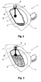
- Figure 2 shows a section through the iron 1, wherein the shape of the liquid container 2 is clearly visible.
- the liquid container 2 has a passage 10 on, which is arranged in the region of the filling opening 6 and at the outwardly a cylindrical filling channel 11 connects.
- a Floating 7 arranged, which is connected via a rod 8 with a display element 9 is, wherein the rod 8 is guided through the passage 10 in the filling channel 11 is.
- the float 7 is preferably in the form of a ball.
- the display element 9 is in the form of a cap whose diameter is larger than that Diameter of the passage 10, so that the display element 9 is not in the liquid container 2 can fall.
- the liquid container 2 In the illustrated position of the iron 1 is the liquid container 2 only slightly filled and is the display element 9 on the liquid container 2 on.
- the filling channel 11 opens in the direction of the housing 6, wherein in End area a ring is provided as a stop element for the display element 9, the a maximum deflection of the display element 9 in the direction of the opening of the filling channel 11 limited.
- the ring is arranged so far at the end of the filling channel 11, that the display element 9 is clearly visible from the outside.
- Figure 3 shows the iron with a higher liquid level in the liquid container 2, in which the floating body 7 is lifted so far in the direction of the filling channel 11, that the display element 9 rests on the ring. In this position of the display element. 9 can the display element 9 from the outside by an operator clearly in the filling channel 11 can be seen. This is a clear indication of a maximum filling of the Liquid container 2 given.
- the float 7 is forcibly guided in its movement by the rod 8, the on the one hand in the implementation 10 and on the other by means of the display element 9 in the channel 11 is guided.
- a trajectory for the float 7th set at the horizontally disposed liquid container 2 substantially in Extension of the channel 11 extends obliquely through the liquid container 2. If the horizontal bracket position and the oblique to vertical filling position of the iron 1 considered as end positions for a range of inclination positions, the Trajectory of the float 7 substantially parallel to the bisector the angle of the two end positions. This results for the level indicator an advantageous display behavior, the following with reference to the schematic representations of Figures 6 and 7 is explained.
- Figure 6 shows in the figures a) to c) each of the liquid container 2 with the half Maximum filling quantity of liquid in three different angular positions, whereby the Plotted by the liquid level levels F1 to F3 are located.
- Figure a) shows the liquid container 2 in the horizontal position
- Figure b) in an oblique
- Figure c) in a vertical position of the iron. 1
- Figure 7 shows in Figures d) to g) respectively the liquid container 2 in one horizontal position with the three marked levels F1 to F3 at different Quantities. Also in FIG. 8, F1 corresponds to the plane of the liquid level in FIG horizontal, F2 of the plane of the liquid level in oblique and F3 of the plane of the Liquid level in vertical position.
- Figure d shows the three levels F1 - F3 at half the filling of the liquid container 2. It can be stated that all three levels F1 - F3 are at the same point Cut P1. It follows that the float 7 at half filling in all three angular positions takes the same place when its trajectory through the Point P1 runs. The lines of intersection of the fluid planes F1 - F3 lie on top of each other or at least close to each other. Thus, in all three angular positions in this Filling quantity the filling quantity is displayed correctly.
- Figure e shows the three levels F1 - F3 at quarter filling of the liquid container 2.
- the three levels F1 - F3 do not intersect at one point. No point can be found that is simultaneously part of all levels F1 - F3 is. This results in the impossibility, the course of the movement path to such Choose that the float 7 occupies the same place in all three angular positions.
- point P2 To the influence of the angular position on the position of the float as possible can be kept small, as point P2, through which the trajectory should run a point to be chosen which is as small as possible for all three levels F1 - F3 Has distance.
- the point P2 can be arranged within the triangle, the is limited by the three levels F1 - F3.
- the point P2 may be in the centroid This triangle will be arranged. Furthermore, there is such a case the possibility to prioritize an angular position and to arrange the point P2, that he is at a lesser distance, in particular to the level that prioritized Angular position corresponds. In the present case, the point P2 was arranged so that he to all levels F1 - F3 has the same distance.
- the three levels F1 - F3 are at three quarters of the liquid container 2 shown. Also in this case, the three levels F1 - F3 do not intersect a point. Again, no point can be found that is simultaneously part of it of all levels F1 - F3, so the course of the trajectory is not chosen that way can be that the float 7 at this capacity in all three angular positions occupy the same place. For the course of the trajectory is the corresponding Point P3 back to the center of the triangle between the three levels F1 - F3 arranged.
- the trajectory shown in Figure g) can now be determined be assembled.
- the path of movement can also be over the Endpoints P1 and P3 are also extended.
- the display element 9 a display panel is assigned with quantities, the indication for the half capacity can so be arranged that the display at this filling level in all angular positions correct is.
- the other quantities and especially for low or high quantities increases the influence of the angular position on the location of the float 7, so that a correct indication of the level may only be for one angular position can be achieved.
- Figures 4 and 5 show a further embodiment of the invention, wherein in the liquid container 2, a guide sleeve 12 is provided.
- the guide sleeve 12 In the guide sleeve 12 is the Float 7 movably arranged, the float 7 in a change in position slides along the guide sleeve along.
- the guide sleeve 12 is formed in the manner that the float 7 at a given maximum liquid volume is arranged in the liquid container 2 in such a way that the display element 9 is located at the stop.
- the guide sleeve 12 has a slot through which the rod 8 at a corresponding Position of the float 7 is guided. Furthermore, 12 recesses in the sleeve introduced so that liquid at a corresponding level of the level can flow into the sleeve 12.
- FIG. 4 shows a horizontal position.
- FIG. 5 shows a second position of the iron, in which usually liquid in the filling channel 11th is filled. Also in this position of the iron 1, the float 7 is at maximum Filling volume of the liquid container 2 raised so high that the display element 9 rests on the ring.
- the display element 9 is formed in the manner that it is designed as a sieve, so that liquid filled through the filling channel 11 is filtered through the sieve.
Landscapes
- Engineering & Computer Science (AREA)
- Textile Engineering (AREA)
- Level Indicators Using A Float (AREA)
- Thermally Insulated Containers For Foods (AREA)
Abstract
Description
- Fig. 1
- eine perspektivische Darstellung eines Bügeleisens,
- Fig. 2
- eine Schnittdarstellung eines Bügeleisens bei einer ersten Füllmenge,
- Fig. 3
- eine Schnittdarstellung eines Bügeleisens bei einer zweiten Füllmenge,
- Fig. 4
- eine Schnittdarstellung eines Bügeleisens mit einem Führungselement für den Schwimmkörper in einer ersten Winkelstellung,
- Fig. 5
- eine Schnittdarstellung eines Bügeleisens gemäß Fig. 4 in einer zweiten Winkelstellung,
- Fig. 6
- schematische Ansichten eines Flüssigkeitsbehälters in verschiedenen Winkelstellungen, und
- Fig. 7
- schematische Ansichten eines Flüssigkeitsbehälters mit verschiedenen Füllmengen.
Claims (17)
- Haushaltsgerät , insbesondere Bügeleisen mit einem Flüssigkeitsbehälter (2) und einer Füllmenge anzeigenden Füllstandsanzeige, dadurch gekennzeichnet, dass die Füllstandsanzeige bei der selben Füllmenge in verschiedenen Neigungslagen des Haushaltsgerätes (1) jeweils zumindest annähernd den gleichen Füllstandswert anzeigt.
- Haushaltsgerät nach Anspruch 1, dadurch gekennzeichnet, dass, ein mit der Flüssigkeit gekoppelter Schwimmkörper (7) vorgesehen ist, der entlang einer Bewegungsbahn zwangsgeführt ist, die derart verläuft, dass für jede bestimmte Füllmenge der Schwimmkörper (7) in den mehreren Neigungslagen die zumindest annähernd gleiche Höhenposition einnimmt.
- Haushaltsgerät nach Anspruch 2, dadurch gekennzeichnet, dass die Bewegungsbahn des Schwimmkörpers (7) entlang einer Reihe von Raumpunkten (P1-P3) verläuft, welche bei der ihnen jeweils zugeordneten Füllmenge einen geringen oder keinen Abstand zu den Flüssigkeitsspiegeln (F1-F3) besitzen, die von der jeweiligen Füllmenge bei den verschiedenen Neigungslagen gebildet werden.
- Haushaltsgerät nach Anspruch 3, dadurch gekennzeichnet, dass die Bewegungsbahn des Schwimmkörpers (7) entlang einer Reihe von Raumpunkten (P1-P3) verläuft, welche bei der ihnen jeweils zugeordneten Füllmenge auf der Schnittgerade von zwei Flüssigkeitsspiegeln (F1, F3) befinden, die von der jeweiligen Füllmenge bei zwei verschiedenen Neigungslagen gebildet werden.
- Haushaltsgerät nach einem der Ansprüche 2 bis 4, dadurch gekennzeichnet, dass die Bewegungsbahn des Schwimmkörpers (7) in einer Ebene liegt, in der die Schnittgerade von zwei Flüssigkeitsspiegeln (F1, F3) liegt, die von der jeweiligen Füllmenge bei zwei verschiedenen Neigungslagen gebildet werden, wobei die Ebene mit diesen zwei Flüssigkeitsspiegeln (F1, F3) jeweils den gleichen Winkel einschließt.
- Haushaltsgerät nach Anspruch 4 oder 5, dadurch gekennzeichnet, dass die beiden Neigungslagen die Endwerte des Bereichs der im Betrieb des Haushaltsgeräts (1) üblicherweise auftretenden Winkelstellungen bilden.
- Haushaltsgerät nach einem der Ansprüche 2 bis 6, dadurch gekennzeichnet, dass der Flüssigkeitsbehälter (2) innen so ausgeformt ist, dass bei verschiedenen Füllmengen die Schnittgeraden der Flüssigkeitsspiegel (F1-F3) bei den unterschiedlichen Neigungslagen aufeinander oder zumindest nahe beieinander liegen.
- Haushaltsgerät nach einem der Ansprüche 2 bis 7, dadurch gekennzeichnet, dass der Schwimmkörper (7) rotationssymmetrisch in Bezug auf eine Symmetrieachse ist, die parallel zur Drehachse der Neigungslagen ist.
- Haushaltsgerät nach einem der Ansprüche 2 bis 7, dadurch gekennzeichnet, dass der Schwimmkörper (7) drehfest mit dem Haushaltsgerät (1) verbunden ist und so geformt ist, dass sich seine Eintauchtiefe in Abhängigkeit der Neigungslagen derart verändert, dass bei gleichbleibender Füllmenge wenigstens ein Punkt des Schwimmkörpers (7) seine Lage in Bezug auf die Bewegungsbahn auch bei sich verändernder Neigungslage des Haushaltsgeräts (1) nicht verändert.
- Haushaltsgerät nach einem der Ansprüche 2 bis 9, dadurch gekennzeichnet, dass ein Führungselement (12) vorgesehen ist, mit dem der Schwimmkörper (7) in der Bewegung festgelegt ist, wobei der Schwimmkörper (7) direkt am Führungselement (12) anliegt.
- Haushaltsgerät nach Anspruch 10, dadurch gekennzeichnet, dass der Schwimmkörper die Form einer Kugel aufweist und das Führungselement (12) als Führungshülse ausgebildet ist, in der der Schwimmkörper in einer vorgegebenen Richtung geführt ist.
- Haushaltsgerät nach einem der Ansprüche 2 bis 9, dadurch gekennzeichnet, dass der Schwimmkörper mit einem drehbar am Flüssigkeitsbehälter (2) gelagerten Schwenkarm verbunden ist.
- Haushaltsgerät nach einem der Ansprüche 2 bis 12, dadurch gekennzeichnet, dass der Schwimmkörper (7) mittels eines Verbindungselements (8) mit einem Anzeigelement (9) verbunden ist, dessen Stellung von der Stellung des Schwimmkörpers (7) abhängt, und das Anzeigeelement (9) außerhalb des Flüssigkeitsbehälters (2) und in der Nähe einer Befüllöffnung (6) des Flüssigkeitsbehälters (2) angeordnet ist.
- Haushaltsgerät nach Anspruch 13, dadurch gekennzeichnet, dass das Anzeigeelement (9) innerhalb eines Einfüllkanals (11) angeordnet ist, der die Befüllöffnung (6) aufweist.
- Haushaltsgerät nach Anspruch 14, dadurch gekennzeichnet, dass das Anzeigeelement (9) als Sieb ausgebildet ist und den Querschnitt des Einfüllkanals (11) abdeckt.
- Haushaltsgerät nach einem der Ansprüche 13 bis 15, dadurch gekennzeichnet, dass das Verbindungselement (8) als Stange ausgebildet ist, die durch eine Wandung des Flüssigkeitsbehälters (2) geführt ist.
- Haushaltsgerät nach einem der Ansprüche 14 bis 16, dadurch gekennzeichnet, dass ein Anschlag im Einfüllkanal (11) vorgesehen ist, der die Bewegung des Anzeigeelementes (9) in Richtung auf den Öffnungsbereich des Kanals (11) auf eine maximale Position begrenzt.
Applications Claiming Priority (2)
| Application Number | Priority Date | Filing Date | Title |
|---|---|---|---|
| DE10155085 | 2001-11-09 | ||
| DE10155085A DE10155085B4 (de) | 2001-11-09 | 2001-11-09 | Haushaltsgerät mit einem Flüssigkeitsbehälter und Füllstandsanzeige |
Publications (3)
| Publication Number | Publication Date |
|---|---|
| EP1310590A2 true EP1310590A2 (de) | 2003-05-14 |
| EP1310590A3 EP1310590A3 (de) | 2003-09-24 |
| EP1310590B1 EP1310590B1 (de) | 2007-04-11 |
Family
ID=7705190
Family Applications (1)
| Application Number | Title | Priority Date | Filing Date |
|---|---|---|---|
| EP02024035A Expired - Lifetime EP1310590B1 (de) | 2001-11-09 | 2002-10-28 | Bügeleisen mit einem Flüssigkeitsbehälter und Füllstandsanzeige |
Country Status (4)
| Country | Link |
|---|---|
| EP (1) | EP1310590B1 (de) |
| AT (1) | ATE359390T1 (de) |
| DE (2) | DE10155085B4 (de) |
| ES (1) | ES2283497T3 (de) |
Cited By (1)
| Publication number | Priority date | Publication date | Assignee | Title |
|---|---|---|---|---|
| EP2108732A1 (de) * | 2008-04-01 | 2009-10-14 | De'Longhi SpA | Verschluss-/Nachfüllvorrichtung für den Tank einer Dampfvorrichtung |
Families Citing this family (1)
| Publication number | Priority date | Publication date | Assignee | Title |
|---|---|---|---|---|
| JP4511144B2 (ja) * | 2003-09-17 | 2010-07-28 | キャタピラージャパン株式会社 | 給油口用ストレーナ |
Citations (1)
| Publication number | Priority date | Publication date | Assignee | Title |
|---|---|---|---|---|
| GB2315403A (en) | 1996-07-24 | 1998-02-04 | Philips Electronics Nv | Electric water heater with water level indicator |
Family Cites Families (9)
| Publication number | Priority date | Publication date | Assignee | Title |
|---|---|---|---|---|
| DE749092C (de) * | 1936-07-16 | 1944-11-15 | Fluessigkeitsstandmesser mit Schwimmer und elektrischer Anzeigevorrichtung | |
| US3298119A (en) * | 1965-10-21 | 1967-01-17 | Sunbeam Corp | Electric pressing iron water level gauge |
| GB1283345A (en) * | 1968-11-20 | 1972-07-26 | Hobbs R Ltd | Kettle |
| FR2278829A1 (fr) * | 1974-07-16 | 1976-02-13 | Celec Sa Const Elect | Perfectionnements aux fers a repasser dits a vapeur |
| DE2717133A1 (de) * | 1977-04-19 | 1978-11-02 | Kloeckner Humboldt Deutz Ag | Vorrichtung zur anzeige des fluessigkeitsstandes in einem behaelter |
| JPS607520B2 (ja) * | 1980-10-24 | 1985-02-25 | 東芝電気器具株式会社 | スチ−ムアイロン |
| JPS5910019U (ja) * | 1982-07-12 | 1984-01-21 | 日産自動車株式会社 | 液面計測装置 |
| DE3445475A1 (de) * | 1984-12-13 | 1986-06-19 | Riesselmann & Sohn, 2842 Lohne | Fuellstandsanzeige fuer fluessigkeitsbehaelter |
| FR2708996B1 (fr) * | 1993-08-13 | 1998-01-16 | Volkswagen Ag | Dispositif de mesure du niveau de remplissage d'un réservoir de liquide, en particulier d'un réservoir de carburant d'un véhicule automobile. |
-
2001
- 2001-11-09 DE DE10155085A patent/DE10155085B4/de not_active Expired - Fee Related
-
2002
- 2002-10-28 DE DE50209906T patent/DE50209906D1/de not_active Expired - Lifetime
- 2002-10-28 EP EP02024035A patent/EP1310590B1/de not_active Expired - Lifetime
- 2002-10-28 AT AT02024035T patent/ATE359390T1/de not_active IP Right Cessation
- 2002-10-28 ES ES02024035T patent/ES2283497T3/es not_active Expired - Lifetime
Patent Citations (1)
| Publication number | Priority date | Publication date | Assignee | Title |
|---|---|---|---|---|
| GB2315403A (en) | 1996-07-24 | 1998-02-04 | Philips Electronics Nv | Electric water heater with water level indicator |
Cited By (1)
| Publication number | Priority date | Publication date | Assignee | Title |
|---|---|---|---|---|
| EP2108732A1 (de) * | 2008-04-01 | 2009-10-14 | De'Longhi SpA | Verschluss-/Nachfüllvorrichtung für den Tank einer Dampfvorrichtung |
Also Published As
| Publication number | Publication date |
|---|---|
| ATE359390T1 (de) | 2007-05-15 |
| DE10155085A1 (de) | 2003-05-28 |
| DE10155085B4 (de) | 2011-07-21 |
| DE50209906D1 (de) | 2007-05-24 |
| EP1310590A3 (de) | 2003-09-24 |
| EP1310590B1 (de) | 2007-04-11 |
| ES2283497T3 (es) | 2007-11-01 |
Similar Documents
| Publication | Publication Date | Title |
|---|---|---|
| DE69909826T2 (de) | Behälter | |
| DE2439400A1 (de) | Vorrichtung zur ueberwachung des fluessigkeitsstandes in einem behaelter, z.b. einer waschmaschine und insbesondere einer geschirrspuelmaschine | |
| DE2812722A1 (de) | Fluessigkeitsstandsanzeiger mit einem vergroesserten anzeigebereich fuer restfluessigkeitsmengen | |
| DE2814789C2 (de) | Vorrichtung zum Überwachen des Niveaus einer Flüssigkeit in einem Behälter | |
| DE2906944B2 (de) | Meßgerät, insbesondere für Kraftstoffbehälter | |
| DE10155085B4 (de) | Haushaltsgerät mit einem Flüssigkeitsbehälter und Füllstandsanzeige | |
| EP0184687A2 (de) | Füllstandsanzeige für Flüssigkeitsbehälter | |
| DE2900413C3 (de) | Flüssigkeitsstandanzeiger, insbesondere für Treibstoffbehälter von Kraftfahrzeugen | |
| DE1148771B (de) | Gas- und Fluessigkeitsmengenmesser mit veraenderlicher Blende | |
| DE4317629A1 (de) | Füllhöhenanzeigevorrichtung | |
| DE69700179T2 (de) | Kaffeemaschine vom "tröpfchenweise" Typ mit einer Dosiervorrichtung für das Kaffeemehl | |
| DE3718199C2 (de) | Vorrichtung zur Abtastung des Flüssigkeitspegels in einem Tank | |
| DE2807041C2 (de) | Vorrichtung zur Gewichtsbestimmung von Flüssigkeiten in Vorratshehältern | |
| DE3236886C2 (de) | ||
| DE29712732U1 (de) | Wassererhitzungsgefäß | |
| DE3242761A1 (de) | Dosiervorrichtung | |
| DE4409554C2 (de) | Füllstandsmeßeinrichtung für einen Flüssigkeitsbehälter, insbesondere einen Kraftstoffbehälter | |
| DE132575C (de) | ||
| DE674635C (de) | Schaltvorrichtung fuer druckluftbelastete Fluessigkeitsakkumulatoren | |
| DE2751507C3 (de) | Magnetischer Schwimmerschalter | |
| DE19750472A1 (de) | Konzentrationsanzeige | |
| DE1954112A1 (de) | Einrichtung zum Messen und analogen Anzeigen des Fluessigkeitsniveaus in Behaeltern | |
| DE537331C (de) | Selbstkassierende Vorrichtung zur Abgabe von Fluessigkeit | |
| DE19539006A1 (de) | Dosierbecher, insbesondere für Pulver- oder Flüssigwaschmittel | |
| DE1841133U (de) | Schwimmerbetaetigter fluessigkeitsstandanzeiger. |
Legal Events
| Date | Code | Title | Description |
|---|---|---|---|
| PUAI | Public reference made under article 153(3) epc to a published international application that has entered the european phase |
Free format text: ORIGINAL CODE: 0009012 |
|
| AK | Designated contracting states |
Designated state(s): AT BE BG CH CY CZ DE DK EE ES FI FR GB GR IE IT LI LU MC NL PT SE SK TR |
|
| AX | Request for extension of the european patent |
Extension state: AL LT LV MK RO SI |
|
| PUAL | Search report despatched |
Free format text: ORIGINAL CODE: 0009013 |
|
| AK | Designated contracting states |
Kind code of ref document: A3 Designated state(s): AT BE BG CH CY CZ DE DK EE ES FI FR GB GR IE IT LI LU MC NL PT SE SK TR |
|
| AX | Request for extension of the european patent |
Extension state: AL LT LV MK RO SI |
|
| RAP1 | Party data changed (applicant data changed or rights of an application transferred) |
Owner name: BSH BOSCH UND SIEMENS HAUSGERAETE GMBH |
|
| 17P | Request for examination filed |
Effective date: 20040324 |
|
| AKX | Designation fees paid |
Designated state(s): AT BE BG CH CY CZ DE DK EE ES FI FR GB GR IE IT LI LU MC NL PT SE SK TR |
|
| 17Q | First examination report despatched |
Effective date: 20050329 |
|
| GRAP | Despatch of communication of intention to grant a patent |
Free format text: ORIGINAL CODE: EPIDOSNIGR1 |
|
| RTI1 | Title (correction) |
Free format text: IRON WITH LIQUID RESERVOIR AND LIQUID-LEVEL INDICATOR |
|
| GRAS | Grant fee paid |
Free format text: ORIGINAL CODE: EPIDOSNIGR3 |
|
| GRAA | (expected) grant |
Free format text: ORIGINAL CODE: 0009210 |
|
| AK | Designated contracting states |
Kind code of ref document: B1 Designated state(s): AT BE BG CH CY CZ DE DK EE ES FI FR GB GR IE IT LI LU MC NL PT SE SK TR |
|
| PG25 | Lapsed in a contracting state [announced via postgrant information from national office to epo] |
Ref country code: FI Free format text: LAPSE BECAUSE OF FAILURE TO SUBMIT A TRANSLATION OF THE DESCRIPTION OR TO PAY THE FEE WITHIN THE PRESCRIBED TIME-LIMIT Effective date: 20070411 |
|
| REG | Reference to a national code |
Ref country code: GB Ref legal event code: FG4D Free format text: NOT ENGLISH |
|
| REG | Reference to a national code |
Ref country code: CH Ref legal event code: EP |
|
| REG | Reference to a national code |
Ref country code: IE Ref legal event code: FG4D Free format text: LANGUAGE OF EP DOCUMENT: GERMAN |
|
| REF | Corresponds to: |
Ref document number: 50209906 Country of ref document: DE Date of ref document: 20070524 Kind code of ref document: P |
|
| GBT | Gb: translation of ep patent filed (gb section 77(6)(a)/1977) |
Effective date: 20070601 |
|
| PG25 | Lapsed in a contracting state [announced via postgrant information from national office to epo] |
Ref country code: SE Free format text: LAPSE BECAUSE OF FAILURE TO SUBMIT A TRANSLATION OF THE DESCRIPTION OR TO PAY THE FEE WITHIN THE PRESCRIBED TIME-LIMIT Effective date: 20070711 |
|
| ET | Fr: translation filed | ||
| PG25 | Lapsed in a contracting state [announced via postgrant information from national office to epo] |
Ref country code: PT Free format text: LAPSE BECAUSE OF FAILURE TO SUBMIT A TRANSLATION OF THE DESCRIPTION OR TO PAY THE FEE WITHIN THE PRESCRIBED TIME-LIMIT Effective date: 20070911 |
|
| NLV1 | Nl: lapsed or annulled due to failure to fulfill the requirements of art. 29p and 29m of the patents act | ||
| REG | Reference to a national code |
Ref country code: ES Ref legal event code: FG2A Ref document number: 2283497 Country of ref document: ES Kind code of ref document: T3 |
|
| REG | Reference to a national code |
Ref country code: IE Ref legal event code: FD4D |
|
| PG25 | Lapsed in a contracting state [announced via postgrant information from national office to epo] |
Ref country code: CZ Free format text: LAPSE BECAUSE OF FAILURE TO SUBMIT A TRANSLATION OF THE DESCRIPTION OR TO PAY THE FEE WITHIN THE PRESCRIBED TIME-LIMIT Effective date: 20070411 Ref country code: NL Free format text: LAPSE BECAUSE OF FAILURE TO SUBMIT A TRANSLATION OF THE DESCRIPTION OR TO PAY THE FEE WITHIN THE PRESCRIBED TIME-LIMIT Effective date: 20070411 Ref country code: IE Free format text: LAPSE BECAUSE OF FAILURE TO SUBMIT A TRANSLATION OF THE DESCRIPTION OR TO PAY THE FEE WITHIN THE PRESCRIBED TIME-LIMIT Effective date: 20070411 Ref country code: BG Free format text: LAPSE BECAUSE OF FAILURE TO SUBMIT A TRANSLATION OF THE DESCRIPTION OR TO PAY THE FEE WITHIN THE PRESCRIBED TIME-LIMIT Effective date: 20070711 Ref country code: DK Free format text: LAPSE BECAUSE OF FAILURE TO SUBMIT A TRANSLATION OF THE DESCRIPTION OR TO PAY THE FEE WITHIN THE PRESCRIBED TIME-LIMIT Effective date: 20070411 |
|
| PLBE | No opposition filed within time limit |
Free format text: ORIGINAL CODE: 0009261 |
|
| STAA | Information on the status of an ep patent application or granted ep patent |
Free format text: STATUS: NO OPPOSITION FILED WITHIN TIME LIMIT |
|
| PG25 | Lapsed in a contracting state [announced via postgrant information from national office to epo] |
Ref country code: SK Free format text: LAPSE BECAUSE OF FAILURE TO SUBMIT A TRANSLATION OF THE DESCRIPTION OR TO PAY THE FEE WITHIN THE PRESCRIBED TIME-LIMIT Effective date: 20070411 |
|
| 26N | No opposition filed |
Effective date: 20080114 |
|
| BERE | Be: lapsed |
Owner name: BSH BOSCH UND SIEMENS HAUSGERATE G.M.B.H. Effective date: 20071031 |
|
| PG25 | Lapsed in a contracting state [announced via postgrant information from national office to epo] |
Ref country code: GR Free format text: LAPSE BECAUSE OF FAILURE TO SUBMIT A TRANSLATION OF THE DESCRIPTION OR TO PAY THE FEE WITHIN THE PRESCRIBED TIME-LIMIT Effective date: 20070712 |
|
| PG25 | Lapsed in a contracting state [announced via postgrant information from national office to epo] |
Ref country code: MC Free format text: LAPSE BECAUSE OF NON-PAYMENT OF DUE FEES Effective date: 20071031 |
|
| REG | Reference to a national code |
Ref country code: CH Ref legal event code: PL |
|
| PG25 | Lapsed in a contracting state [announced via postgrant information from national office to epo] |
Ref country code: CH Free format text: LAPSE BECAUSE OF NON-PAYMENT OF DUE FEES Effective date: 20071031 Ref country code: LI Free format text: LAPSE BECAUSE OF NON-PAYMENT OF DUE FEES Effective date: 20071031 |
|
| PG25 | Lapsed in a contracting state [announced via postgrant information from national office to epo] |
Ref country code: BE Free format text: LAPSE BECAUSE OF NON-PAYMENT OF DUE FEES Effective date: 20071031 |
|
| PG25 | Lapsed in a contracting state [announced via postgrant information from national office to epo] |
Ref country code: EE Free format text: LAPSE BECAUSE OF FAILURE TO SUBMIT A TRANSLATION OF THE DESCRIPTION OR TO PAY THE FEE WITHIN THE PRESCRIBED TIME-LIMIT Effective date: 20070411 |
|
| PG25 | Lapsed in a contracting state [announced via postgrant information from national office to epo] |
Ref country code: AT Free format text: LAPSE BECAUSE OF NON-PAYMENT OF DUE FEES Effective date: 20071028 |
|
| PG25 | Lapsed in a contracting state [announced via postgrant information from national office to epo] |
Ref country code: CY Free format text: LAPSE BECAUSE OF FAILURE TO SUBMIT A TRANSLATION OF THE DESCRIPTION OR TO PAY THE FEE WITHIN THE PRESCRIBED TIME-LIMIT Effective date: 20070411 |
|
| PG25 | Lapsed in a contracting state [announced via postgrant information from national office to epo] |
Ref country code: LU Free format text: LAPSE BECAUSE OF NON-PAYMENT OF DUE FEES Effective date: 20071028 |
|
| PG25 | Lapsed in a contracting state [announced via postgrant information from national office to epo] |
Ref country code: TR Free format text: LAPSE BECAUSE OF FAILURE TO SUBMIT A TRANSLATION OF THE DESCRIPTION OR TO PAY THE FEE WITHIN THE PRESCRIBED TIME-LIMIT Effective date: 20070411 |
|
| REG | Reference to a national code |
Ref country code: DE Ref legal event code: R081 Ref document number: 50209906 Country of ref document: DE Owner name: BSH HAUSGERAETE GMBH, DE Free format text: FORMER OWNER: BSH BOSCH UND SIEMENS HAUSGERAETE GMBH, 81739 MUENCHEN, DE Effective date: 20150407 |
|
| REG | Reference to a national code |
Ref country code: ES Ref legal event code: PC2A Owner name: BSH HAUSGERATE GMBH Effective date: 20150527 |
|
| REG | Reference to a national code |
Ref country code: FR Ref legal event code: PLFP Year of fee payment: 14 |
|
| REG | Reference to a national code |
Ref country code: FR Ref legal event code: CD Owner name: BSH HAUSGERATE GMBH Effective date: 20151022 |
|
| REG | Reference to a national code |
Ref country code: FR Ref legal event code: PLFP Year of fee payment: 15 |
|
| REG | Reference to a national code |
Ref country code: FR Ref legal event code: PLFP Year of fee payment: 16 |
|
| PGFP | Annual fee paid to national office [announced via postgrant information from national office to epo] |
Ref country code: FR Payment date: 20171023 Year of fee payment: 16 Ref country code: DE Payment date: 20171031 Year of fee payment: 16 |
|
| PGFP | Annual fee paid to national office [announced via postgrant information from national office to epo] |
Ref country code: GB Payment date: 20171024 Year of fee payment: 16 Ref country code: IT Payment date: 20171020 Year of fee payment: 16 Ref country code: ES Payment date: 20171103 Year of fee payment: 16 |
|
| REG | Reference to a national code |
Ref country code: DE Ref legal event code: R119 Ref document number: 50209906 Country of ref document: DE |
|
| GBPC | Gb: european patent ceased through non-payment of renewal fee |
Effective date: 20181028 |
|
| PG25 | Lapsed in a contracting state [announced via postgrant information from national office to epo] |
Ref country code: DE Free format text: LAPSE BECAUSE OF NON-PAYMENT OF DUE FEES Effective date: 20190501 |
|
| PG25 | Lapsed in a contracting state [announced via postgrant information from national office to epo] |
Ref country code: FR Free format text: LAPSE BECAUSE OF NON-PAYMENT OF DUE FEES Effective date: 20181031 |
|
| PG25 | Lapsed in a contracting state [announced via postgrant information from national office to epo] |
Ref country code: GB Free format text: LAPSE BECAUSE OF NON-PAYMENT OF DUE FEES Effective date: 20181028 Ref country code: IT Free format text: LAPSE BECAUSE OF NON-PAYMENT OF DUE FEES Effective date: 20181028 |
|
| REG | Reference to a national code |
Ref country code: ES Ref legal event code: FD2A Effective date: 20191203 |
|
| PG25 | Lapsed in a contracting state [announced via postgrant information from national office to epo] |
Ref country code: ES Free format text: LAPSE BECAUSE OF NON-PAYMENT OF DUE FEES Effective date: 20181029 |