EP1309366B1 - Vorrichtung zur verabreichung von medikamenten mit einem halter für eine kassette - Google Patents
Vorrichtung zur verabreichung von medikamenten mit einem halter für eine kassette Download PDFInfo
- Publication number
- EP1309366B1 EP1309366B1 EP01957777A EP01957777A EP1309366B1 EP 1309366 B1 EP1309366 B1 EP 1309366B1 EP 01957777 A EP01957777 A EP 01957777A EP 01957777 A EP01957777 A EP 01957777A EP 1309366 B1 EP1309366 B1 EP 1309366B1
- Authority
- EP
- European Patent Office
- Prior art keywords
- cartridge
- support
- information
- electrically
- electrically connecting
- Prior art date
- Legal status (The legal status is an assumption and is not a legal conclusion. Google has not performed a legal analysis and makes no representation as to the accuracy of the status listed.)
- Expired - Lifetime
Links
Images


Classifications
-
- A—HUMAN NECESSITIES
- A61—MEDICAL OR VETERINARY SCIENCE; HYGIENE
- A61M—DEVICES FOR INTRODUCING MEDIA INTO, OR ONTO, THE BODY; DEVICES FOR TRANSDUCING BODY MEDIA OR FOR TAKING MEDIA FROM THE BODY; DEVICES FOR PRODUCING OR ENDING SLEEP OR STUPOR
- A61M5/00—Devices for bringing media into the body in a subcutaneous, intra-vascular or intramuscular way; Accessories therefor, e.g. filling or cleaning devices, arm-rests
- A61M5/178—Syringes
- A61M5/24—Ampoule syringes, i.e. syringes with needle for use in combination with replaceable ampoules or carpules, e.g. automatic
-
- A—HUMAN NECESSITIES
- A61—MEDICAL OR VETERINARY SCIENCE; HYGIENE
- A61M—DEVICES FOR INTRODUCING MEDIA INTO, OR ONTO, THE BODY; DEVICES FOR TRANSDUCING BODY MEDIA OR FOR TAKING MEDIA FROM THE BODY; DEVICES FOR PRODUCING OR ENDING SLEEP OR STUPOR
- A61M2205/00—General characteristics of the apparatus
- A61M2205/50—General characteristics of the apparatus with microprocessors or computers
-
- A—HUMAN NECESSITIES
- A61—MEDICAL OR VETERINARY SCIENCE; HYGIENE
- A61M—DEVICES FOR INTRODUCING MEDIA INTO, OR ONTO, THE BODY; DEVICES FOR TRANSDUCING BODY MEDIA OR FOR TAKING MEDIA FROM THE BODY; DEVICES FOR PRODUCING OR ENDING SLEEP OR STUPOR
- A61M2205/00—General characteristics of the apparatus
- A61M2205/60—General characteristics of the apparatus with identification means
- A61M2205/6018—General characteristics of the apparatus with identification means providing set-up signals for the apparatus configuration
-
- A—HUMAN NECESSITIES
- A61—MEDICAL OR VETERINARY SCIENCE; HYGIENE
- A61M—DEVICES FOR INTRODUCING MEDIA INTO, OR ONTO, THE BODY; DEVICES FOR TRANSDUCING BODY MEDIA OR FOR TAKING MEDIA FROM THE BODY; DEVICES FOR PRODUCING OR ENDING SLEEP OR STUPOR
- A61M2205/00—General characteristics of the apparatus
- A61M2205/60—General characteristics of the apparatus with identification means
- A61M2205/6027—Electric-conductive bridges closing detection circuits, with or without identifying elements, e.g. resistances, zener-diodes
-
- A—HUMAN NECESSITIES
- A61—MEDICAL OR VETERINARY SCIENCE; HYGIENE
- A61M—DEVICES FOR INTRODUCING MEDIA INTO, OR ONTO, THE BODY; DEVICES FOR TRANSDUCING BODY MEDIA OR FOR TAKING MEDIA FROM THE BODY; DEVICES FOR PRODUCING OR ENDING SLEEP OR STUPOR
- A61M2205/00—General characteristics of the apparatus
- A61M2205/60—General characteristics of the apparatus with identification means
- A61M2205/6063—Optical identification systems
- A61M2205/6072—Bar codes
-
- A—HUMAN NECESSITIES
- A61—MEDICAL OR VETERINARY SCIENCE; HYGIENE
- A61M—DEVICES FOR INTRODUCING MEDIA INTO, OR ONTO, THE BODY; DEVICES FOR TRANSDUCING BODY MEDIA OR FOR TAKING MEDIA FROM THE BODY; DEVICES FOR PRODUCING OR ENDING SLEEP OR STUPOR
- A61M5/00—Devices for bringing media into the body in a subcutaneous, intra-vascular or intramuscular way; Accessories therefor, e.g. filling or cleaning devices, arm-rests
- A61M5/14—Infusion devices, e.g. infusing by gravity; Blood infusion; Accessories therefor
- A61M5/142—Pressure infusion, e.g. using pumps
- A61M5/145—Pressure infusion, e.g. using pumps using pressurised reservoirs, e.g. pressurised by means of pistons
- A61M5/1452—Pressure infusion, e.g. using pumps using pressurised reservoirs, e.g. pressurised by means of pistons pressurised by means of pistons
- A61M5/14546—Front-loading type injectors
Definitions
- the invention relates to the electronic marking of cartridges or the like.
- the invention relates specifically to: A medication delivery device comprising a support for a cartridge provided with one or more electronically readable information carrying areas.
- the following account of the prior art relates to one of the areas of application of the present invention, the electronic marking of medication cartridges.
- the marking of medication cartridges to be able to electronically read details of its contents is of increasing importance, i.a. to ensure a safe and convenient use of the medication in connection with a patient's self-treatment of a disease such as diabetes. In order for the user to feel secure about handling the medication it is important that errors in his or hers use of the drug are avoided.
- One remedy to avoid errors is an intelligent marking of the contents (i.e. drug, concentration, relevant dose, last day of use, etc.) of the medication cartridge.
- This includes a visually intelligible marking of the cartridge for reading by a user as well as an electronically readable code for use by a processing unit of the medication delivery device, the processing unit being used for monitoring and controlling the actual delivery of the medication to the user and for making a record of the drug administration history, etc.
- a certain area of the medication cartridge must be reserved to hosting an increasing amount of information.
- US-A-5 569 212 discloses an apparatus for electrically determining and recording the dose of an agent delivered with a syringe consisting of a barrel for holding the agent and a plunger for expelling the agent.
- the syringe has a conducting path with an input terminal and an output terminal, and at least one electrically resistive element, whose resistance changes depending on the position of the plunger inside the barrel.
- the apparatus produces a voltage difference across the terminals and causes an electric current to flow through the conducting path.
- An electric response measuring device preferably an ammeter, measures the electric current delivered from the syringe's output terminal and calculates the dose there from.
- US-A-5,954,700 discloses a cartridge for containing a fluid and for use with an electronic delivery device that includes a cartridge housing for holding the fluid, and an information providing source.
- the information-providing source may be a set of wires and contacts, or contact bands that provide the predetermined information to an electronic delivery device by producing a binary code.
- To implement a specific binary code requires an individual customisation of the cartridge as regards the contacts or contact bands and the wires connecting them to a positive or negative voltage.
- Another remedy for avoiding errors and for making the user feel comfortable with the handling is that the drug contained in the medication cartridge is visible from outside, so that the user is able to check the color, the uniformity, whether impurities are present, etc. For this reason, as large a part of the surface of the medication cartridge as possible should be free of labels and other opaque items that limit a user's view of the contents. Further, there is a general trend to miniaturization of electronic devices including medication delivery devices, so that they are easy to carry and discreet in use.
- the object of the present invention is to provide means, which are capable of securely transferring information with an increased density from a cartridge to an electronic circuit, and which are flexible and may be customized to a variety of physical designs.
- the medication delivery device comprises a support for the cartridge wherein the support is made of elastic materials and is at least partially constituted by one or more electrically connecting supports, each comprising a number of closely spaced mutually electrically insulated conductors embedded in an electrically insulating material that stretches from one of the supporting surfaces of the cartridge to a contact area for receiving and transferring the information, when said cartridge is positioned in said support.
- each of said one or more electrically connecting supports is constituted by alternating layers of electrically conducting material of maximum thickness T cl and electrically insulating material of maximum thickness T il , respectively, it is ensured that a simple and flexible solution is provided.
- the maximum density of information may be controlled.
- said support When said support is made of elastic materials, it may be ensured that the support conforms to the shape of the cartridge when the cartridge is positioned in the support with a certain minimum pressure. I.e. it makes the support even more flexible and relaxes the tolerances to its conformity with the cartridge and with the contact area (e.g. pads on a printed circuit board (PCB) for connecting to a processing circuit on the PCB).
- PCB printed circuit board
- said one or more electrically connecting supports are made of elastomeric materials.
- said electrically conducting material consists of silicone rubber with a concentration of carbon black sufficient for electrical conduction.
- said cartridge has an axial direction of symmetry, and said information carrying areas are located preferably in one axial end of the cartridge, it is ensured that the main part of the cartridge is not covered by the electronically readable information and may be held free for optical inspection of the contents of the cartridge (in case of a transparent cartridge).
- the electronically readable information may be densely written and thus be concentrated to an end of the cartridge that is used for a lid or cover, in which case the whole effective volume available for housing the medication may be open for inspection.
- said cartridge has an axial direction of symmetry, and said information carrying areas are located preferably in an axial direction of the cartridge covering only a limited angular sector, it is ensured that the whole length of the cartridge in its axial direction may be used for coding information and at the same time it is possible to inspect the contents of the cartridge over the full axial length of the cartridge.
- said support comprises one electrically connecting support preferably stretching in an axial direction of the cartridge.
- said support comprises two or more electrically connecting supports each stretching preferably in an axial direction of the cartridge and being located side by side along the radial periphery of the cartridge, it is ensured that the electronically readable information may be written several times in information carrying areas distributed along the radial periphery of the cartridge and that two or more of the areas may be simultaneously read.
- the information in each area may be different, in which case the information capacity is increased.
- the information in each area may be redundantly provided by coding the same information in all areas or by alternatingly coding its binary true and inverted forms. The redundancy may be used to implement checks to improve reading security.
- the surface of the support facing towards the cartridge including the one or more electrically connecting supports, in an axial cross section correspond to the surface of the cartridge, it is ensured that the cartridge is received and supported in an optimal way if the support is made of a relatively inelastic material.
- the surface of the support facing towards the cartridge including the one or more electrically connecting supports, in an axial cross section essentially correspond to the surface of the cartridge, when said cartridge is positioned in said support, it is ensured that the cartridge is received and supported in an optimal way if the support is made of a relatively elastic material.
- said contact area consists of groups of identical and regularly spaced electrically conducting pads of width Wcp in the direction of adjacent pads, adjacent pads being separated by an electrically insulating area of width Diacp, and the following relations between said distances are fulfilled: Diacp > 2 * T cl , and Wcp > T il + T cl , it is ensured that the electrical states of adjacent (possibly abutted) predefined positions are not transferred to the same pad (Diacp > 2*T cl ), and that at least one conducting layer contacts any given pad (Wcp > T il + T cl ).
- said cartridge has an axial direction of symmetry
- said cartridge is provided with a multitude of rectangular, essentially parallel, identically sized information carrying areas of height Hica in the direction of a circumference of said axis of symmetry, said information carrying areas being spaced with equal mutual distance Dica along the periphery of the cartridge in the direction of a circumference of said axis of symmetry
- said supporting means comprise two rectangular, essentially parallel, identical electrically connecting supports of height Hctm in the direction perpendicular to the axis of symmetry of the cartridge, separated by an electrically insulating volume of width Dctm between the two electrically connecting supports, and the following relations between said distances are fulfilled: Hica ⁇ Dctm ⁇ 2 * Hica + Dica , and Hctm ⁇ Dica ⁇ 2 * Hctm + Dctm , it is ensured that the cartridge cannot be positioned in such a way that a given information carrying area has contact to two electrically connecting supports at the same time (Hica ⁇ D
- the cartridge cannot be positioned in such a way that a given electrically connecting support has contact to two information carrying areas at the same time (Hctm ⁇ Dica). It is further ensured that the cartridge cannot be positioned in such a way that the electrically connecting supports fall entirely between two information carrying areas, in which case they would not have contact to any of the information carrying areas of the cartridge (Dica ⁇ 2*Hctm + Dctm). It is further ensured that the cartridge cannot be positioned in such a way that two adjacent information carrying areas fall entirely between the electrically connecting supports, in which case the latter might not have contact to any of the information carrying areas of the cartridge (Dctm ⁇ 2*Hica + Dica).
- said information carrying areas of height Hica each consist of electrically conducting and electrically insulating rectangular patches provided at said predefined positions on said cartridge according to a binary representation of said item of information
- said patches having a width Wpda abut each other, and the sum of the maximum thicknesses T cl and T il of said alternating layers of electrically conducting and electrically insulating materials, respectively, constituting said electrically connecting supports, is less than the width Wpda of said patches, thus fulfilling the following relation between said distances: Wpda > T il + T cl , it is ensured that each patch has contact to at least one of the conducting layers of an electrically connecting support when the cartridge is properly placed in the support.
- a composite material comprising a number of closely spaced mutually electrically insulated conductors embedded in an electrically insulating material is used at least for the partial support of a cartridge and for the transfer of an electronically readable information from information carrying areas on said cartridge to a contact area, a secure transfer of information with an increased density from a cartridge to an electronic circuit is provided.
- said closely spaced mutually electrically insulated conductors embedded in an electrically insulating material are constituted by alternating layers of electrically conducting material and electrically insulating material, respectively, it is ensured that that a simple and flexible solution is provided.
- said alternating layers of electrically conducting material and electrically insulating material, respectively are made of elastomeric materials.
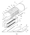
- Figs. 1-3 show a cartridge containing an electrically readable information in the form of patterns of electrically conducting and electrically insulating areas and a support according to the invention comprising one or more electrically connecting supports for transferring the information to an electronic circuit.
- a support according to the invention has the combined function of receiving and mechanically supporting a part of the cartridge provided with information carrying areas AND of transferring the information from the these information carrying areas to an electronic circuit for further processing.
- the cartridge 10, 20, 30, respectively is only partially shown, as indicated by the 'broken' outline in the righthand part of the cartridge.
- the cartridge possesses a rotational symmetry as indicated by the arrow 11, 21, 31, symbolizing the axis of symmetry.
- a label 12, 22, 32 containing information carrying areas laid out in the axial direction of the cartridge is located on the outer surface at one axial end of the cartridge, where a lid 13, 23, 33, optionally in the form of a piston when the cartridge is a replaceable medication cartridge for a medication delivery device, provides a closure of the cartridge.
- the label 12, 22, 32 comprises an electrically conducting foil 120, 220, 320 having information carrying areas 121-127, 221-227, 325 extending in the axial direction of the cartridge.
- a multitude of information carrying areas (121-127, 221-227, respectively, plus the ones situated on the hidden part of the surface) are evenly distributed on the surface of the cartridge in a radial direction (i.e. along the whole periphery encircling the axial direction of the cartridge).
- Each information carrying area comprising patterns of electrically conducting and electrically insulating patches, thus only covers a limited radial sector of the surface.
- only one information carrying area 325 is indicated. This extends, however, along the whole periphery of the cartridge (i.e. the item of information is represented by closed rings 3251-3260 of electrically conducting and electrically insulating areas).
- Each of the information carrying areas 121-127, 221-227, 325 contains an item of information in the form of patterns of electrically conducting and electrically insulating areas. Each pattern represents an item of information in binary form. Each bit of information is represented by an electrically characteristic layer in a predefined position in the information carrying area. A binary one in a specific predefined position may be represented by an electrically conducting layer covering that predefined position, and a binary zero in a specific predefined position may be represented by an electrically insulating layer covering that predefined position. Alternatively, binary one may be represented by an insulating layer and binary zero by a conducting layer.
- foils 120, 220, 320 in figs. 1-3 containing the information carrying areas 121-127, 221-227, 325 are electrically conducting, it is only necessary to apply an electrically insulating layer (e.g. a paint) to the predefined positions representing one of the a binary states (in this embodiment 'zero').
- an electrically insulating layer e.g. a paint
- the cartridge is shown in a position just above the support 15, 25, 35, respectively, which, again for illustrative purposes, is shown just above a PCB with electronic components and connecting wires 16, 26, 36 containing pads 163, 263, 264, 363 with electrical connections, symbolically indicated by an arrow 162, 262, 362, to a processing unit 161, 261, 361, e.g. a microprocessor.
- the support consists of one or more electrically connecting supports 151, 251, 252, 351 embedded in an electrically insulating material 155, 255, 355.
- the electrically connecting supports comprise alternating layers of electrically conducting 1511, 2511, 3511 and electrically insulating 1512, 2512, 3512 layers of an elastomeric material, e.g. silicone rubber with the electrically conducting layer having a concentration of carbon black sufficient for electrical conduction.
- Each electrically conducting layer is electrically insulated from all other electrically conducting layers, so that each electrically conducting layer in effect represents an insulated conductor.
- the supports 15, 25, 35 including the electrically connecting supports 151, 251, 252, 351 are shown to be adapted to receive the curved shape of the part of the cartridge, where the information carrying areas 121-127, 221-227, 325 are located, by shaping them equivalently. This makes possible the use of non-elastic materials for the support, if convenient.
- the support is placed (and optionally fastened) on the PCB 160, 260, 360 so that electrical contact between the electrically connecting supports 151, 251, 252, 351 and the pads 163, 263, 264, 363 is ensured.
- the cartridge is positioned on the support so that electrical contact between one (figs. 1, 3) or two (fig. 2) of the information carrying areas in their full axial lengths (i.e. involving all patches of a given information carrying area representing bits of information) and the electrically connecting supports is ensured.
- the geometrical dimensions of the patches, layers and pads and mutual distance between adjacent information carrying areas on the cartridge and corresponding electrically connecting supports are discussed below with reference to figs. 6 and 8.
- this potential will be transferred from those predefined areas containing a conductive layer (i.e. in the present embodiment those predefined areas not being covered by an insulating layer) to the corresponding pads on the PCB.
- a direct measure of the pattern of binary states of the information carrying area connected to the pads by a given electrically connecting support is presented on the inputs of the processing unit, possibly by appropriately terminating the inputs with pull-up or pull-down circuitry depending on the potential applied to the electrically conducting foil and the definition of the binary states.
- a specific part of the foil may be preferably reserved to the application of the electric potential (e.g. an area of the foil circumfering the cartridge and not occupied by information carrying areas, in fig. 3 e.g. the part of the foil 320 not covered by information bits in predefined positions 321-330).
- the support 15, 25, 35 is only shown as having an axial length corresponding to the axial length of the corresponding information carrying areas (e.g. 125 in fig. 1) but it may of course extend in both axial directions if appropriate for the application in question.
- the support is shown to cover a certain radial sector (less than 90 degrees), but it may of course cover any radial sector, including 360 degrees, if appropriate.
- the sector covered by the support is less than 180 degrees allowing a direct 'vertical' placement of the cartridge in the support (in opposition to the case of a 360 degrees support, where the cartridge has to be axially inserted).
- the label 12, 22, 32 containing information carrying areas 121-127, 221-227, 325 is placed in one axial end of the cartridge 10, 20, 30 covering only the space occupied by the axial extent of the lid/piston 13, 23, 33 to ensure that a full view of the contents of the cartridge is available for inspection.
- the information carrying areas extend in the axial direction of the cartridge. They might as well extend in a radial direction (as discussed in connection with figs. 4 and 5) or in a direction there between (e.g. forming one or more helixes on the surface of the cartridge), if convenient, as long as the support, including the electrically connecting support(s), is adapted thereto.
- the electrical connections, schematically indicated by an arrow 162, 262, 362, connecting the pads 163, 263, 264, 363 with the processing unit 161, 261, 361 may be a one to one parallel set of electrical connections between each pad and a corresponding input on the processor 161, 261, 361, but it may also comprise a multiplexing or coding unit to reduce the number of necessary inputs to the processing unit.
- Fig. 1 shows a cartridge containing an electrically readable information in the form of patterns of patches in the axial direction of the cartridge and a support according to the invention comprising one electrically connecting support for transferring the information to an electronic circuit.
- the binary information contained in each of the information carrying areas 121, 122, 123, 124, 125, 126, 127 is the same as schematically indicated in the information carrying areas 125 and 126 in that the patterns of electrically conducting patches, exemplified by 1250, 1260 (no filling), and electrically insulating patches, exemplified by 1251, 1261 (hatched), are identical.
- the embodiment in fig. 1 benefits from the rotational symmetry of the cartridge 10 and the label 12 with identical information carrying areas 121-127 equally distributed on the label along the periphery of the cartridge in that it only requires the user to position the cartridge properly in a radial direction (possibly involving a slight rotation of the cartridge around its axis of symmetry) to ensure that an electrical contact between one of the information carrying areas 121-127 and the electrically connecting support 151 is present (since the positioning in an axial direction 11 may be mechanically ensured by receiving means for the cartridge).
- the control of the cartridge being correctly positioned may be in the hands of the processing unit 161, which, if necessary, may indicate to the user via a display (not shown) or a voice interface that a corrective action is required, and which may block further use of the device, if the cartridge is not correctly positioned.
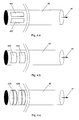
- Fig. 2 shows a cartridge containing an electrically readable information in the form of patterns of patches in the axial direction of the cartridge and a support according to the invention comprising two electrically connecting supports for transferring the information to an electronic circuit.
- the support 25 comprises two electrically connecting supports 251, 252 for simultaneously reading two items of information from two information carrying areas (e.g. 225, 226) on the cartridge 20.
- the evenly distributed information carrying areas 221-227 contain an item of information in a true binary form alternating with the information in its inverted form as indicated by the schematically illustrated patterns of electrically conducting 2261 and insulating 2251 patches in information carrying areas 225 and 226, respectively, one pattern being the inverse of the other.
- the embodiment of fig. 2 has the advantage of reading the information in a binary true and inverted form, which allows the safety in reading to be improved.
- the same binary representation of the item of information may be provided in all information carrying areas (as in fig. 1) and read twice, which also allows an improved safety in reading.
- the electrically conducting 'end'-patches 2250, 2260 may be used for connecting a power supply voltage.
- Fig. 3 shows a cartridge containing an electrically readable information in the form of ring patterns and a support according to the invention comprising one electrically connecting support for transferring the information to an electronic circuit.
- the support 35 comprises only one electrically connecting support 351 for reading an item of information from an information carrying area 325 on the cartridge 30.
- the information carrying area 325 extends along the whole periphery of the cartridge 30.
- a binary representation of the item of information is implemented by closed rings 3251-3260 of electrically conducting and electrically insulating areas in predefined positions.
- Figs. 4.a-4.e show various ways of placing information carrying areas for holding electronically readable information on a cartridge.
- Figs. 4.a-4.d show a cartridge 40 with an axis of rotational symmetry 41 and information carrying areas located at one axial end of the cartridge.
- Fig. 4.a shows two information carrying areas 401, 402 positioned side by side in a radial direction on the surface of the cartridge 40 (i.e. along the periphery perpendicular to the axis of symmetry). Each information carrying area covers only a limited radial sector of the surface.
- Fig. 4.b shows two information carrying areas 403, 404 positioned side by side in the axial direction 41 on the surface of the cartridge 40 (i.e. along the periphery parallel to the axis of symmetry). Each information carrying area 403, 404 covers only a limited radial sector of the surface.
- Fig. 4.c shows two information carrying areas 405, 406 positioned side by side in the axial direction on the surface of the cartridge 40 (i.e. along the periphery parallel to the axis of symmetry 41). Each information carrying area 405, 406 encircles the entire radial periphery of the cartridge.
- Fig. 4.d shows information carrying areas 410, 411, 412, 413, 414 positioned side by side, evenly distributed in a radial direction on the surface of the cartridge 40 (i.e. along the periphery perpendicular to the axis of symmetry). Each information carrying area covers only a limited radial sector of the surface. Information carrying areas 410, 411, 412, 413, 414 plus identical ones situated on the hidden part of the surface are evenly distributed on the surface of the cartridge in a radial direction, i.e. extending along the whole periphery encircling the axial direction of the cartridge.
- Fig. 4.e shows an information carrying area 415 extending along the major part of the axial length of the cartridge 40.
- the information carrying area is located within in a surface area 420 corresponding to a radial sector 421.
- a single information carrying area is shown within the surface area 420.
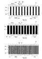
- Figs. 5.a-5.e show various ways of laying out the electrically conducting and electrically insulating areas in predefined positions within an information carrying area, implementing a binary representation of an item of information in its true and inverted form.
- Each information carrying area has a rectangular shape defining a longitudinal direction as the direction defined by its longest side.
- a direction is also defined by the direction perpendicular to the face between two neighboring predefined positions each containing a specific bit of information.
- Fig. 5.a shows an embodiment with two information carrying areas 50, 51 located side by side in a direction perpendicular to the direction 505 defined by adjacent predefined positions.
- Each individual bit of information is implemented as a patch of electrically conducting 511 (no filling) or electrically insulating 501 (hatched) material located at a specific predefined position of the information carrying area. Neighboring patches abut each other.
- the structure of information carrying areas 50, 51 may e.g. be used in figs. 4.a. and 4.d.
- Fig. 5.b shows an embodiment with two information carrying areas 52, 53 located side by side in a direction perpendicular to the direction 525 defined by adjacent predefined positions.
- Each individual bit of information is implemented as a patch of electrically conducting 531 (no filling) or electrically insulating 521 (hatched) material located at a specific predefined position of the information carrying area.
- Neighboring patches are separated by a an 'empty' space 520, 530 of width equal to the width of each of the information carrying patches 521, 531.
- the 'empty' space may consist of an electrically conducting or insulating layer (as long as the pads on the PCB (cf. figs. 1-3) are correspondingly laid out).
- the structure of information carrying areas 52, 53 may e.g. be used in figs. 4.a. and 4.d.
- Fig. 5.c shows an embodiment with two information carrying areas 54, 55 located side by side in a direction 545 defined by adjacent predefined positions.
- Each individual bit of information is implemented as a patch of electrically conducting 551 (no filling) or electrically insulating 541 (hatched) material located at a specific predefined position of the information carrying area. Neighboring patches abut each other.
- the structure of information carrying areas 54, 55 may e.g. be used in figs. 4.a. and 4.d.
- Fig. 5.d shows an embodiment with two information carrying areas 56, 57 located side by side in a direction 565 defined by adjacent predefined positions.
- Each individual bit of information is implemented as a patch of electrically conducting 562, 571 (no filling) or electrically insulating 561, 572 (hatched) material located at a specific predefined position of the information carrying area. Neighboring patches abut each other.
- the structure of information carrying areas 56, 57 may e.g. be used in figs. 4.b. and 4.c.
- Fig. 5.e shows an embodiment with two information carrying areas 58, 59 located side by side in a direction perpendicular to the direction 585 defined by adjacent predefined positions.
- Each individual bit of information is implemented as a patch of electrically conducting 591 (no filling) or electrically insulating 581 (hatched) material located at a specific predefined position of the information carrying area. Neighboring patches abut each other.
- the structure of information carrying areas 58, 59 may e.g. be used in figs. 4.b. and 4.c.
- Figs. 6.a-6.c show various geometries of an electrically connecting support according to the invention.
- Fig. 6.a shows an embodiment of an electrically connecting support 60, where the thickness T il 630 of the insulating layer 63 is larger than the thickness T cl 640 of the conducting layer 64.
- the patches 61 of the information carrying area are shown to be of equal width Wpda 610 and to abut each other.
- the pads 62 on the PCB are shown to have equal width Wcp 620 and to be evenly distributed with a distance Diacp 621 between each pad.
- Fig. 6.b shows an embodiment of an electrically connecting support 60, where the thickness T il of the insulating layer 63 is smaller than the thickness T cl of the conducting layer 64.
- Fig. 6.c shows an embodiment of an electrically connecting support 60, where the thickness T il of the insulating layer 63 equals the thickness T cl of the conducting layer 64.
- the relation Diacp > 2*T cl makes sure that the electrical states of adjacent information carrying patches on the cartridge are not transferred to the same pad in the contact area under the assumption that the border between adjacent patches is located at a position 'corresponding to midway between two pads'.
- the fulfillment of the relation Wcp > T il + T cl ensures that at least one conducting layer contacts any given pad.
- the fulfillment of the relation Wpda > T il + T cl ensures that each patch has contact to at least one of the conducting layers of an electrically connecting support, when the cartridge is properly placed in the support.
- the information carrying patches on the cartridge are shown as abutted. This need not be the case. They may have any width Wpda as long as the relation Wpda > T il + T cl is fulfilled to ensure that at least one conducting layer contacts any given information carrying patch.
- the relations reflect the minimum distances of pads and patches and between pads and thus for given layer thicknesses determine the information density (minimum width per bit).
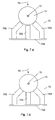
- Fig. 7.a-7.b show an example of a cartridge and a support according to the invention comprising three electrically connecting supports made of elastic materials.
- Fig. 7.a shows a cartridge 71 having an axis of rotational symmetry 72 being positioned just above a support 70 comprising three individual electrically connecting supports 701, 702, 703 ready for receiving the cartridge.
- the cartridge is provided with information carrying areas positioned on the cartridge along its radial periphery with a spacing corresponding to the geometry of the electrically connecting supports 701, 702, 703.
- the space between the electrically connecting supports may be filled with an isolating material (e.g. silicone rubber), not shown.
- the cartridge 71 is positioned in the support 70 and fixed with a slight downwards pressure indicated by the arrow 73.
- the support including the electrically connecting supports 701, 702, 703 is made of elastic materials so that it conforms to the shape of the cartridge over the axial length of the support, when the cartridge is placed in the support.
- the three items of information that may be simultaneously read may be identical, in which case the redundancy may be used to improve the safety in reading (by a simple majority test or by more advanced error correcting techniques), or they may be different, in which case a larger amount of information may be read from the cartridge.
- Fig. 8 shows geometries involved in reading an item of information provided a multitude of times along the periphery of a cartridge with a rotational symmetry by means of two electrically connecting supports.
- the electrically connecting supports 81, 82 are shown in a position where they read information from information carrying areas 830, 840, respectively, and transfer the information to groups of pads 83, 84, respectively, on a PCB.
- the information carrying areas 810, 820, 830, 840, 850, 860 on a label 80 carry an item of information alternatingly in a binary true and inverted form as indicated by the schematically shown individual patches of equal width Wpda 89.
- the patches are either electrically conducting 8102 (no filling) or electrically insulating 8101 (hatched).
- Hica ⁇ Dctm ensures that the cartridge cannot be positioned in such a way that a given information carrying area has contact to two electrically connecting supports at the same time.
- Hctm ⁇ Dica ensures that the cartridge cannot be positioned in such a way that a given electrically connecting support has contact to two information carrying areas at the same time.
- Dica ⁇ 2*Hctm + Dctm ensures that the cartridge cannot be positioned in such a way that the electrically connecting supports fall entirely between two information carrying areas, in which case they would not have contact to any of the information carrying areas of the cartridge.
- Dctm ⁇ 2*Hica + Dica ensures that the cartridge cannot be positioned in such a way that two adjacent information carrying areas fall entirely between the electrically connecting supports, in which case the latter might not have contact to any of the information carrying areas of the cartridge.
- Dctm + Hctm Dica + Hica, which ensures that the electrically connecting supports 81, 82 will have contact to two of the information carrying areas irrespective of the radial orientation of the cartridge in the support.
Claims (14)
- Medikamentenabgabevorrichtung, umfassend einen Halter (15; 25; 35) für eine Patrone (10; 20; 30; 40), versehen mit einem oder mehreren elektronisch lesbaren Informationen tragenden Bereich(en) (121, 122, 123, 124, 125, 126, 127), wobei der Halter (15; 25; 35) zumindest teilweise durch einen oder mehrere elektrisch verbindende(n) Halter (151; 251, 252; 351) gebildet ist,
dadurch gekennzeichnet, dass
der Halter (15; 25; 35) aus elastischen Materialien hergestellt ist, und dass die elektrisch verbindenden Halter (151; 251, 252; 351) jeweils eine Anzahl an eng voneinander beabstandeten elektrisch isolierten Leitern (1511; 2511; 3511) umfassen, die in einem elektrisch isolierenden Material (1512, 155; 2512, 255; 3512, 355) eingebettet sind, das sich von den Auflageflächen der Patrone zu einem Kontaktbereich (163; 263; 264; 363) zum Empfangen und Übertragen der Information erstreckt, wenn sich die Patrone (10; 20; 30; 40) im Halter (15; 25; 35) befindet. - Medikamentenabgabevorrichtung nach Anspruch 1,
dadurch gekennzeichnet, dass
der eine oder die mehreren elektrisch verbindenden Halter (151; 251, 252; 351) durch wechselnde Schichten aus elektrisch leitendem Material (1511; 2511; 3511) mit einer Maximaldicke Tcl (640) bzw. elektrisch isolierendem Material (1512; 2512; 3512) mit einer Maximaldicke Til (630) gebildet ist/sind. - Halter nach Anspruch 1 oder 2,
dadurch gekennzeichnet, dass
der Halter (15; 25; 35; 70) mit der Gestalt der Patrone (10; 20; 30; 40; 71) übereinstimmt, wenn sich die Patrone im Halter befindet. - Medikamentenabgabevorrichtung nach einem der Ansprüche 1-3,
dadurch gekennzeichnet, dass
der eine oder die mehreren elektrisch verbindenden Halter (151; 251, 252; 351) aus elastomeren Materialien hergestellt ist/sind. - Medikamentenabgabevorrichtung nach einem der Ansprüche 2-4,
dadurch gekennzeichnet, dass
das elektrisch leitende Material (1511; 2511; 3511) aus Siliconkautschuk mit einer zum elektrischen Leiten ausreichenden Rußkonzentration besteht. - Medikamentenabgabevorrichtung nach einem der Ansprüche 1-5,
dadurch gekennzeichnet, dass
die Patrone (40) eine Symmetrieachsenrichtung (41) aufweist und die Informationen tragenden Bereiche (401, 402; 403, 404; 405, 406; 410, 411, 412, 413, 414) vorzugsweise in einem Achsenende der Patrone lokalisiert sind. - Medikamentenabgabevorrichtung nach einem der Ansprüche 1-5,
dadurch gekennzeichnet, dass
die Patrone (40) eine Symmetrieachsenrichtung (41) aufweist und die Informationen tragenden Bereiche (415) vorzugsweise in einer Achsenrichtung der Patrone lokalisiert sind, die nur einen begrenzten ringförmigen Abschnitt (421) abdeckt. - Medikamentenabgabevorrichtung nach einem der Ansprüche 1-7,
dadurch gekennzeichnet, dass
der Halter (15; 35) einen elektrisch verbindenden Halter (151; 351) umfasst, der sich vorzugsweise in einer Achsenrichtung der Patrone (10; 30) erstreckt. - Medikamentenabgabevorrichtung nach einem der Ansprüche 1-7,
dadurch gekennzeichnet, dass
der Halter (25; 70) zwei oder mehrere elektrisch verbindende Halter (251, 252; 701, 702, 703) umfasst, die sich jeweils vorzugsweise in einer Achsenrichtung (21; 72) der Patrone (20; 71) erstrecken und nebeneinander entlang der Radialperipherie der Patrone lokalisiert sind. - Medikamentenabgabevorrichtung nach einem der Ansprüche 1-9,
dadurch gekennzeichnet, dass
die Oberfläche des Halters (15; 25; 35), die der Patrone (10; 20; 30) zugewandt ist, einschließend den einen oder die mehreren elektrisch verbindenden Halter (151; 251, 252; 351), in einem Achsenquerschnitt der Oberfläche der Patrone entspricht. - Medikamentenabgabevorrichtung nach einem der Ansprüche 1-9,
dadurch gekennzeichnet, dass
die Oberfläche des Halters (70), die der Patrone (71) zugewandt ist, einschließend den einen oder die mehreren elektrisch verbindenden Halter (701, 702, 703) in einem Achsenquerschnitt im Wesentlichen der Oberfläche der Patrone entspricht, wenn sich die Patrone im Halter befindet. - Medikamentenabgabevorrichtung nach einem der Ansprüche 1-11,
dadurch gekennzeichnet, dass
die Patrone (10) eine Symmetrieachsenrichtung (11) aufweist und der Kontaktbereich (163) aus Gruppen von identischen und regelmäßig beabstandeten elektrisch leitenden Pads (62) mit einer Breite Wcp (620) in der Richtung von benachbarten Pads besteht wobei benachbarte Pads durch einen elektrisch isolierenden Bereich mit einer Breite Diacp (621 getrennt sind, und die folgenden Beziehungen zwischen den Abständen erfüllt sind:

- Medikamentenabgabevorrichtung nach einem der Ansprüche 1-12,
dadurch gekennzeichnet, dass
die Patrone (20) eine Symmetrieachsenrichtung (21) aufweist und die Patrone mit einer Vielzahl an rechtwinkligen, im Wesentlichen parallelen, identisch bemessenen Informationen tragenden Bereichen (810, 820, 830, 840, 850, 860) mit einer Höhe Hica (87) in der Richtung eines Umfangs (80) der Symmetrieachse (21) versehen ist, wobei die Informationen tragenden Bereiche mit einem gleichen gegenseitigen Abstand Diac (88) entlang der Peripherie der Patrone in Richtung eines Umfangs (80) der Symmetrieachse (21) beabstandet sind und die Haltermittel (25) zwei rechtwinklige, im Wesentlichen parallele, identische elektrisch verbindende Halter (251, 252; 81, 82) mit einer Höhe Hctm (85) in der Richtung senkrecht zur Symmetrieachse der Patrone, getrennt durch ein elektrisch isolierendes Volumen (255) mit einer Breite Dctm (86) zwischen den beiden elektrisch verbindenden Trägern umfassen und die folgenden Beziehungen zwischen den Abständen erfüllt sind:

- Medikamentenabgabevorrichtung nach Anspruch 13,
dadurch gekennzeichnet, dass
die Informationen tragenden Bereiche (810, 820, 830, 840, 850, 860) mit einer Höhe Hica (87) jeweils aus elektrisch leitenden (8102) und elektrisch isolierenden (8101) rechtwinkligen Patches bestehen, die an den vorher definierten Positionen auf der Patrone gemäß einer binären Darstellung des Informationspunkts bereitgestellt sind, wobei die Patches (8101, 8102) mit einer Breite Wpda (89) aneinander stoßen und die Summe der Maximaldicken Tcl (640) und Til (630) der wechselnden Schichten aus elektrisch leitenden (64) bzw. elektrisch isolierenden (63) Materialien, die die elektrisch verbindenden Halter (81, 82) bilden, geringer ist als die Breite Wpda (89) der Patches, wodurch die folgende Beziehung zwischen den Abständen erfüllt ist:
Applications Claiming Priority (3)
| Application Number | Priority Date | Filing Date | Title |
|---|---|---|---|
| DKPA200001200 | 2000-08-10 | ||
| DK200001200 | 2000-08-10 | ||
| PCT/DK2001/000531 WO2002011792A1 (en) | 2000-08-10 | 2001-08-09 | A support for a cartridge for transferring an electronically readable information to an electronic circuit, and use of a composite material in a support |
Publications (2)
| Publication Number | Publication Date |
|---|---|
| EP1309366A1 EP1309366A1 (de) | 2003-05-14 |
| EP1309366B1 true EP1309366B1 (de) | 2007-02-21 |
Family
ID=8159647
Family Applications (1)
| Application Number | Title | Priority Date | Filing Date |
|---|---|---|---|
| EP01957777A Expired - Lifetime EP1309366B1 (de) | 2000-08-10 | 2001-08-09 | Vorrichtung zur verabreichung von medikamenten mit einem halter für eine kassette |
Country Status (6)
| Country | Link |
|---|---|
| US (1) | US7922096B2 (de) |
| EP (1) | EP1309366B1 (de) |
| AT (1) | ATE354389T1 (de) |
| AU (1) | AU2001279600A1 (de) |
| DE (1) | DE60126782T2 (de) |
| WO (1) | WO2002011792A1 (de) |
Cited By (22)
| Publication number | Priority date | Publication date | Assignee | Title |
|---|---|---|---|---|
| US7682338B2 (en) | 2006-08-23 | 2010-03-23 | Medtronic Minimed, Inc. | Infusion medium delivery system, device and method with needle inserter and needle inserter device and method |
| US7686787B2 (en) | 2005-05-06 | 2010-03-30 | Medtronic Minimed, Inc. | Infusion device and method with disposable portion |
| US7736344B2 (en) | 2006-08-23 | 2010-06-15 | Medtronic Minimed, Inc. | Infusion medium delivery device and method with drive device for driving plunger in reservoir |
| US7794434B2 (en) | 2006-08-23 | 2010-09-14 | Medtronic Minimed, Inc. | Systems and methods allowing for reservoir filling and infusion medium delivery |
| US7811262B2 (en) | 2006-08-23 | 2010-10-12 | Medtronic Minimed, Inc. | Systems and methods allowing for reservoir filling and infusion medium delivery |
| US7828764B2 (en) | 2006-08-23 | 2010-11-09 | Medtronic Minimed, Inc. | Systems and methods allowing for reservoir filling and infusion medium delivery |
| US7959715B2 (en) | 2007-04-30 | 2011-06-14 | Medtronic Minimed, Inc. | Systems and methods allowing for reservoir air bubble management |
| US7963954B2 (en) | 2007-04-30 | 2011-06-21 | Medtronic Minimed, Inc. | Automated filling systems and methods |
| US8025658B2 (en) | 2007-04-30 | 2011-09-27 | Medtronic Minimed, Inc. | Adhesive patch systems and methods |
| US8137314B2 (en) | 2006-08-23 | 2012-03-20 | Medtronic Minimed, Inc. | Infusion medium delivery device and method with compressible or curved reservoir or conduit |
| US8187228B2 (en) | 2006-08-23 | 2012-05-29 | Medtronic Minimed, Inc. | Infusion pumps and methods and delivery devices and methods with same |
| US8277415B2 (en) | 2006-08-23 | 2012-10-02 | Medtronic Minimed, Inc. | Infusion medium delivery device and method with drive device for driving plunger in reservoir |
| US8303574B2 (en) | 2006-02-09 | 2012-11-06 | Deka Products Limited Partnership | Adhesive and peripheral systems and methods for medical devices |
| US8323250B2 (en) | 2007-04-30 | 2012-12-04 | Medtronic Minimed, Inc. | Adhesive patch systems and methods |
| US8414563B2 (en) | 2007-12-31 | 2013-04-09 | Deka Products Limited Partnership | Pump assembly with switch |
| US8434528B2 (en) | 2007-04-30 | 2013-05-07 | Medtronic Minimed, Inc. | Systems and methods for reservoir filling |
| US8496646B2 (en) | 2007-02-09 | 2013-07-30 | Deka Products Limited Partnership | Infusion pump assembly |
| US8512288B2 (en) | 2006-08-23 | 2013-08-20 | Medtronic Minimed, Inc. | Infusion medium delivery device and method with drive device for driving plunger in reservoir |
| US8597243B2 (en) | 2007-04-30 | 2013-12-03 | Medtronic Minimed, Inc. | Systems and methods allowing for reservoir air bubble management |
| US8613725B2 (en) | 2007-04-30 | 2013-12-24 | Medtronic Minimed, Inc. | Reservoir systems and methods |
| US8840586B2 (en) | 2006-08-23 | 2014-09-23 | Medtronic Minimed, Inc. | Systems and methods allowing for reservoir filling and infusion medium delivery |
| US11964126B2 (en) | 2021-06-04 | 2024-04-23 | Deka Products Limited Partnership | Infusion pump assembly |
Families Citing this family (39)
| Publication number | Priority date | Publication date | Assignee | Title |
|---|---|---|---|---|
| DE602004015432D1 (de) * | 2003-03-24 | 2008-09-11 | Novo Nordisk As | Transparentes elektronisches markieren eines medikamentenbehälters |
| DE602006019712D1 (de) | 2005-05-10 | 2011-03-03 | Novo Nordisk As | |
| US8852164B2 (en) | 2006-02-09 | 2014-10-07 | Deka Products Limited Partnership | Method and system for shape-memory alloy wire control |
| US7958456B2 (en) | 2005-12-23 | 2011-06-07 | Apple Inc. | Scrolling list with floating adjacent index symbols |
| US11364335B2 (en) | 2006-02-09 | 2022-06-21 | Deka Products Limited Partnership | Apparatus, system and method for fluid delivery |
| US11478623B2 (en) | 2006-02-09 | 2022-10-25 | Deka Products Limited Partnership | Infusion pump assembly |
| US10010669B2 (en) | 2006-02-09 | 2018-07-03 | Deka Products Limited Partnership | Systems and methods for fluid delivery |
| US11497846B2 (en) | 2006-02-09 | 2022-11-15 | Deka Products Limited Partnership | Patch-sized fluid delivery systems and methods |
| US8994382B2 (en) | 2006-04-12 | 2015-03-31 | Novo Nordisk A/S | Absolute position determination of movably mounted member in medication delivery device |
| US8564544B2 (en) | 2006-09-06 | 2013-10-22 | Apple Inc. | Touch screen device, method, and graphical user interface for customizing display of content category icons |
| US8689132B2 (en) | 2007-01-07 | 2014-04-01 | Apple Inc. | Portable electronic device, method, and graphical user interface for displaying electronic documents and lists |
| US10188787B2 (en) | 2007-12-31 | 2019-01-29 | Deka Products Limited Partnership | Apparatus, system and method for fluid delivery |
| US8900188B2 (en) | 2007-12-31 | 2014-12-02 | Deka Products Limited Partnership | Split ring resonator antenna adapted for use in wirelessly controlled medical device |
| US10080704B2 (en) | 2007-12-31 | 2018-09-25 | Deka Products Limited Partnership | Apparatus, system and method for fluid delivery |
| US8881774B2 (en) | 2007-12-31 | 2014-11-11 | Deka Research & Development Corp. | Apparatus, system and method for fluid delivery |
| US9456955B2 (en) | 2007-12-31 | 2016-10-04 | Deka Products Limited Partnership | Apparatus, system and method for fluid delivery |
| US8986253B2 (en) | 2008-01-25 | 2015-03-24 | Tandem Diabetes Care, Inc. | Two chamber pumps and related methods |
| US8052645B2 (en) | 2008-07-23 | 2011-11-08 | Avant Medical Corp. | System and method for an injection using a syringe needle |
| US8177749B2 (en) | 2008-05-20 | 2012-05-15 | Avant Medical Corp. | Cassette for a hidden injection needle |
| CA3070618C (en) | 2008-05-20 | 2021-07-20 | Avant Medical Corp. | Autoinjector system |
| US8408421B2 (en) | 2008-09-16 | 2013-04-02 | Tandem Diabetes Care, Inc. | Flow regulating stopcocks and related methods |
| US8650937B2 (en) | 2008-09-19 | 2014-02-18 | Tandem Diabetes Care, Inc. | Solute concentration measurement device and related methods |
| WO2010092156A1 (en) | 2009-02-13 | 2010-08-19 | Novo Nordisk A/S | Medical device and cartridge |
| US8572513B2 (en) | 2009-03-16 | 2013-10-29 | Apple Inc. | Device, method, and graphical user interface for moving a current position in content at a variable scrubbing rate |
| CA2768011C (en) | 2009-07-15 | 2018-07-24 | Deka Products Limited Partnership | Apparatus, systems and methods for an infusion pump assembly |
| EP2724739B1 (de) | 2009-07-30 | 2015-07-01 | Tandem Diabetes Care, Inc. | Tragbares Infusionspumpensystem |
| US8624933B2 (en) | 2009-09-25 | 2014-01-07 | Apple Inc. | Device, method, and graphical user interface for scrolling a multi-section document |
| US10092706B2 (en) | 2011-04-20 | 2018-10-09 | Amgen Inc. | Autoinjector apparatus |
| WO2013134519A2 (en) | 2012-03-07 | 2013-09-12 | Deka Products Limited Partnership | Apparatus, system and method for fluid delivery |
| USD898908S1 (en) | 2012-04-20 | 2020-10-13 | Amgen Inc. | Pharmaceutical product cassette for an injection device |
| US9180242B2 (en) | 2012-05-17 | 2015-11-10 | Tandem Diabetes Care, Inc. | Methods and devices for multiple fluid transfer |
| US20140026474A1 (en) * | 2012-07-25 | 2014-01-30 | Charles J. Kulas | Automated grow system |
| US9173998B2 (en) | 2013-03-14 | 2015-11-03 | Tandem Diabetes Care, Inc. | System and method for detecting occlusions in an infusion pump |
| JP6768501B2 (ja) | 2013-03-15 | 2020-10-14 | アムゲン・インコーポレーテッド | 薬物カセット、自動注入機、および自動注入機システム |
| CA2904725C (en) | 2013-03-15 | 2022-04-12 | Amgen Inc. | Drug cassette, autoinjector, and autoinjector system |
| CA2914977C (en) | 2013-07-03 | 2021-11-02 | Deka Products Limited Partnership | Apparatus, system and method for fluid delivery |
| US9978043B2 (en) | 2014-05-30 | 2018-05-22 | Apple Inc. | Automatic event scheduling |
| CN116301544A (zh) | 2014-06-27 | 2023-06-23 | 苹果公司 | 尺寸减小的用户界面 |
| WO2019209963A1 (en) | 2018-04-24 | 2019-10-31 | Deka Products Limited Partnership | Apparatus and system for fluid delivery |
Family Cites Families (183)
| Publication number | Priority date | Publication date | Assignee | Title |
|---|---|---|---|---|
| US495956A (en) * | 1893-04-25 | Process of making whisky | ||
| SE332089B (de) | 1965-06-14 | 1971-01-25 | Svenska Dataregister Ab | |
| US3700862A (en) | 1969-08-26 | 1972-10-24 | Diginetics Inc | Indicia system for credit cards and the like |
| US3916157A (en) | 1970-09-08 | 1975-10-28 | Mmbi Inc | Specimen carrier |
| JPS5187787A (en) | 1975-01-31 | 1976-07-31 | Shinetsu Polymer Co | Intaa konekutaa |
| DE2636634A1 (de) | 1976-08-13 | 1978-02-16 | Siemens Ag | Identifikationssystem fuer probenroehrchen |
| US4179212A (en) | 1977-09-06 | 1979-12-18 | Xerox Corporation | Demand publishing royalty accounting system |
| SE411392B (sv) | 1977-12-09 | 1979-12-17 | Inst Mikrovagsteknik Vid Tekni | Metanordning for kapacitiv bestemning av det inbordes leget hos tva relativt varandra rorliga delar |
| DE2845401C2 (de) | 1978-10-18 | 1980-10-02 | Gao Gesellschaft Fuer Automation Und Organisation Mbh, 8000 Muenchen | Bedrucktes Wertpapier mit Echtheitsmerkmalen und Verfahren zur Prüfung seineT Echtheit |
| US4327283A (en) | 1979-09-24 | 1982-04-27 | Rca Corporation | Workpiece with machine-readable marking recessed therein and method of making same |
| US4355300A (en) | 1980-02-14 | 1982-10-19 | Coulter Systems Corporation | Indicia recognition apparatus |
| US4385234A (en) | 1980-11-25 | 1983-05-24 | Bei Electronics, Inc. | Optical systems for optical encoders |
| DE3133826A1 (de) | 1981-08-27 | 1983-03-10 | Boehringer Mannheim Gmbh, 6800 Mannheim | Analyseteststreifen und verfahren zu seiner herstellung |
| US4476381A (en) | 1982-02-24 | 1984-10-09 | Rubin Martin I | Patient treatment method |
| US4449042A (en) | 1982-03-01 | 1984-05-15 | Can And Bottle Systems, Inc. | Redeemable container with end closure redemption code |
| US4636786A (en) | 1982-12-20 | 1987-01-13 | Motorola, Inc. | Electrooptic ceramic display and method for making same |
| US4625101A (en) | 1984-02-27 | 1986-11-25 | The Goodyear Tire & Rubber Company | Bar code configuration and method of molding |
| GB8407276D0 (en) | 1984-03-21 | 1984-04-26 | Plessey Co Plc | Electrical connectors |
| US4693574A (en) | 1984-07-27 | 1987-09-15 | Canon Kabushiki Kaisha | Film information reading device |
| DE3428847A1 (de) | 1984-08-04 | 1986-02-13 | Bosch Gmbh Robert | Verfahren zur erfassung von navigationsdaten |
| DE3616046C2 (de) | 1985-05-13 | 1996-04-25 | Ricoh Kk | Flüssigkristall-Anzeigevorrichtung mit einer Leiterplatte |
| DE3606163A1 (de) | 1986-02-26 | 1987-08-27 | Hoechst Ag | Vorrichtung zur applikation von arzneimittelsuspensionen |
| DE248165T1 (de) | 1986-04-04 | 1988-04-28 | Mitutoyo Mfg. Co., Ltd., Tokio/Tokyo, Jp | Transduktor vom kapazitiven typ fuer lagemessungen. |
| US4857716A (en) | 1986-05-12 | 1989-08-15 | Clinicom Incorporated | Patient identification and verification system and method |
| US4739377A (en) | 1986-10-10 | 1988-04-19 | Eastman Kodak Company | Confidential document reproduction method and apparatus |
| US4810867A (en) | 1987-02-04 | 1989-03-07 | M. E. Cunningham Company | Bar code marking the surface of an object |
| DE3712089A1 (de) | 1987-04-09 | 1988-10-27 | Jaspal Singh | Anordnung zur identifizierung des papillarlinienmusters eines fingers |
| NL8701091A (nl) | 1987-05-08 | 1988-12-01 | Spruyt Hillen Bv | Injectiepen. |
| US4880014A (en) | 1987-08-14 | 1989-11-14 | Zarowitz Barbara J | Method for determining therapeutic drug dosage using bioelectrical resistance and reactance measurements |
| US4853521A (en) | 1987-12-28 | 1989-08-01 | Claeys Ronald W | System for verifying and recording drug administration to a patient |
| GB2216259A (en) | 1988-03-31 | 1989-10-04 | Microvol Ltd | Dispenser for chemical analysis carrying a code |
| US4896029A (en) | 1988-04-08 | 1990-01-23 | United Parcel Service Of America, Inc. | Polygonal information encoding article, process and system |
| US4959056A (en) | 1988-06-14 | 1990-09-25 | Wayne State University | Digital dispenser |
| US4943279A (en) | 1988-09-30 | 1990-07-24 | C. R. Bard, Inc. | Medical pump with infusion controlled by a detachable coded label |
| DE58909370D1 (de) | 1988-09-30 | 1995-09-07 | Landis & Gry Tech Innovat Ag | Strichkodefeld und Strichkodeleser. |
| US5153827A (en) | 1989-01-30 | 1992-10-06 | Omni-Flow, Inc. | An infusion management and pumping system having an alarm handling system |
| JPH06105323B2 (ja) | 1989-03-31 | 1994-12-21 | 工業技術院長 | 光走査用回折格子 |
| US4930263A (en) | 1989-05-18 | 1990-06-05 | Spectra-Physics, Inc. | Forming markings on a vial surface |
| US5311364A (en) | 1989-08-30 | 1994-05-10 | Ricoh Company, Ltd. | Reading lens for scanner |
| DE3931828A1 (de) | 1989-09-23 | 1991-04-04 | Krieg Gunther | Streifencode sowie verfahren und vorrichtung zum lesen eines solchen |
| US4978335A (en) | 1989-09-29 | 1990-12-18 | Medex, Inc. | Infusion pump with bar code input to computer |
| US5504316A (en) | 1990-05-08 | 1996-04-02 | Symbol Technologies, Inc. | Laser scanning system and scanning method for reading 1-D and 2-D barcode symbols |
| US5176502A (en) | 1990-04-25 | 1993-01-05 | Becton, Dickinson And Company | Syringe pump and the like for delivering medication |
| US5078683A (en) | 1990-05-04 | 1992-01-07 | Block Medical, Inc. | Programmable infusion system |
| US5174766A (en) | 1990-05-11 | 1992-12-29 | Canon Kabushiki Kaisha | Electrical connecting member and electric circuit member |
| DE4016434A1 (de) | 1990-05-22 | 1991-11-28 | Bosch Gmbh Robert | Kapazitiver stellungsgeber |
| US5305147A (en) | 1990-08-20 | 1994-04-19 | Olympus Optical Co., Ltd. | Eyepiece lens system for endoscopes |
| JPH04222084A (ja) | 1990-12-22 | 1992-08-12 | Nhk Spring Co Ltd | 対象物の識別構造 |
| DK17791D0 (da) | 1991-02-01 | 1991-02-01 | Novo Nordisk As | Beholderinspektion |
| US5132026A (en) | 1991-03-21 | 1992-07-21 | Alpha Therapeutic Corporation | Blood plasma collection system |
| US5196683A (en) | 1991-04-08 | 1993-03-23 | Symbol Technologies, Inc. | Bar code acquisition utilizing moire patterns |
| EP0587669A4 (de) | 1991-06-05 | 1995-02-22 | Mikoh Pty Ltd | Brechungsgitter enthaltende, optische speicher. |
| DE9112592U1 (de) | 1991-10-10 | 1993-02-04 | Papst-Motoren Gmbh & Co Kg, 7742 St Georgen, De | |
| US5379131A (en) | 1991-12-11 | 1995-01-03 | Dai Nippon Printing Co., Ltd. | Method of preventing forgery of diffraction grating pattern and forgery-proof diffraction grating pattern recording structure |
| US5764457A (en) | 1992-01-10 | 1998-06-09 | Deutsche Thomson-Brandt Gmbh | Cassette including a recording medium for a recording apparatus |
| US5336871A (en) | 1992-02-07 | 1994-08-09 | American Bank Note Holographics, Incorporated | Holographic enhancement of card security |
| US5432329A (en) | 1992-02-07 | 1995-07-11 | American Bank Note Holographics | Automated holographic optical recognition and decoding system for verification |
| JPH05307139A (ja) | 1992-04-28 | 1993-11-19 | Olympus Optical Co Ltd | 内視鏡対物レンズ |
| US5383858B1 (en) | 1992-08-17 | 1996-10-29 | Medrad Inc | Front-loading medical injector and syringe for use therewith |
| IT1255495B (it) | 1992-09-18 | 1995-11-09 | Francesco Bellifemine | Dispositivo per la sorveglianza di un impianto di fleboclisi |
| JPH06139845A (ja) | 1992-10-27 | 1994-05-20 | Matsushita Electric Ind Co Ltd | パターン化した透明導電膜の形成方法 |
| US5782814A (en) | 1994-07-22 | 1998-07-21 | Raya Systems, Inc. | Apparatus for determining and recording injection doses in syringes using electrical inductance |
| US5569212A (en) * | 1994-07-22 | 1996-10-29 | Raya Systems, Inc. | Apparatus for electrically determining injection doses in syringes |
| US6068615A (en) | 1994-07-22 | 2000-05-30 | Health Hero Network, Inc. | Inductance-based dose measurement in syringes |
| US5422472A (en) | 1992-12-04 | 1995-06-06 | Psc, Inc. | Optical symbol (bar code) reading systems having an electro-optic receptor with embedded grating rings |
| DE4402319A1 (de) | 1993-01-30 | 1994-08-04 | Bosch Gmbh Robert | Bewegungsmeßsystem für eine Einrichtung mit zwei gegenseitig verschiebbaren Körpern |
| DE4310808C2 (de) | 1993-04-02 | 1995-06-22 | Boehringer Mannheim Gmbh | System zur Dosierung von Flüssigkeiten |
| GB9309151D0 (en) | 1993-05-04 | 1993-06-16 | Zeneca Ltd | Syringes and syringe pumps |
| US5394206A (en) | 1993-06-04 | 1995-02-28 | Eastman Kodak Company | Orientation independent, detachable film cartridge, memory module |
| US5880683A (en) | 1993-07-22 | 1999-03-09 | Bourns, Inc. | Absolute digital position encoder |
| US5793502A (en) | 1993-08-31 | 1998-08-11 | Bianco; James S. | Secure optical identification means and method with enhanced variability |
| JP3483217B2 (ja) | 1994-02-08 | 2004-01-06 | チノン株式会社 | 画像読取装置 |
| GB9403925D0 (en) | 1994-03-01 | 1994-04-20 | Virtuality Entertainment Ltd | Optical system |
| US5536249A (en) * | 1994-03-09 | 1996-07-16 | Visionary Medical Products, Inc. | Pen-type injector with a microprocessor and blood characteristic monitor |
| DE4408050A1 (de) | 1994-03-10 | 1995-09-14 | Thomson Brandt Gmbh | Vorrichtung zur Umwandlung einer mechanischen in eine elektrische Größe |
| IL110318A (en) | 1994-05-23 | 1998-12-27 | Al Coat Ltd | Solutions containing polyaniline for making transparent electrodes for liquid crystal devices |
| US6164534A (en) | 1996-04-04 | 2000-12-26 | Rathus; Spencer A. | Method and apparatus for accessing electronic data via a familiar printed medium |
| US5792117A (en) | 1994-07-22 | 1998-08-11 | Raya Systems, Inc. | Apparatus for optically determining and electronically recording injection doses in syringes |
| US6110148A (en) | 1994-07-22 | 2000-08-29 | Health Hero Network, Inc. | Capacitance-based dose measurements in syringes |
| JPH0855181A (ja) | 1994-08-10 | 1996-02-27 | Kansai Paint Co Ltd | インビジブルマーキングの読取り法 |
| WO1996007479A1 (fr) | 1994-09-09 | 1996-03-14 | Gay Freres Vente Et Exportation S.A. | Dispositif d'enregistrement et de transfert d'informations pour analyses en eprouvette |
| US5895369A (en) | 1994-09-30 | 1999-04-20 | Becton Dickinson And Company | Iontophoresis patch/controller interconnection using a conductive elastomer to provide noise-free electrical contact between patch and controller |
| US5691646A (en) | 1994-12-07 | 1997-11-25 | Mitutoya Corporation | Capacitance-type displacement measuring device with electrodes having spiral patterns |
| DE69526635T2 (de) | 1994-12-29 | 2002-12-05 | Koninkl Philips Electronics Nv | Bilderzeugungsgerät und Verfahren zur Verbesserung geometrischer optischer Bildverzerrungen |
| ATE170014T1 (de) | 1995-05-05 | 1998-09-15 | Landis & Gyr Tech Innovat | Verfahren zum aufbringen eines sicherheitselementes auf ein substrat |
| US5757521A (en) | 1995-05-11 | 1998-05-26 | Advanced Deposition Technologies, Inc. | Pattern metallized optical varying security devices |
| US5786584A (en) | 1995-09-06 | 1998-07-28 | Eli Lilly And Company | Vial and cartridge reading device providing audio feedback for a blood glucose monitoring system |
| US5637854A (en) | 1995-09-22 | 1997-06-10 | Microscan Systems Incorporated | Optical bar code scanner having object detection |
| US6886748B1 (en) | 1996-01-02 | 2005-05-03 | Steven Jerome Moore | Apparatus and method for purchased product security |
| US5628309A (en) | 1996-01-25 | 1997-05-13 | Raya Systems, Inc. | Meter for electrically measuring and recording injection syringe doses |
| GB9601969D0 (en) | 1996-01-31 | 1996-04-03 | Meldet Ltd | A system for the delivery of drugs and therapeutic agents |
| JP3068483B2 (ja) | 1996-02-08 | 2000-07-24 | 株式会社東芝 | パターン読み出し方法、および光学的信号読み取り装置 |
| US5902990A (en) | 1996-02-09 | 1999-05-11 | Stewart; William C. | Bar code scanner guide |
| US6958245B2 (en) | 1996-04-25 | 2005-10-25 | Bioarray Solutions Ltd. | Array cytometry |
| US5821524A (en) | 1996-08-19 | 1998-10-13 | Pharmacopeia, Inc. | Method and apparatus for reading bar coded tubular members such as cylindrical vials |
| DE19637967A1 (de) | 1996-09-18 | 1997-10-30 | Contelec Ag | Winkelsensor |
| EP0833278A3 (de) | 1996-09-19 | 1998-07-29 | Abbott Laboratories | Datenträger |
| JP3824357B2 (ja) | 1996-09-27 | 2006-09-20 | 沖電気工業株式会社 | 光半導体装置 |
| US6047892A (en) | 1996-12-09 | 2000-04-11 | Symbol Technologies, Inc. | Two-dimensional bar code symbology using implicit version information encoding |
| GB2322443A (en) | 1997-02-24 | 1998-08-26 | Secr Defence | Recognition system for verifying an identifier on an article |
| US7061831B2 (en) | 1997-03-28 | 2006-06-13 | Carlos De La Huerga | Product labeling method and apparatus |
| US7041941B2 (en) | 1997-04-07 | 2006-05-09 | Patented Medical Solutions, Llc | Medical item thermal treatment systems and method of monitoring medical items for compliance with prescribed requirements |
| US6168080B1 (en) | 1997-04-17 | 2001-01-02 | Translucent Technologies, Llc | Capacitive method and apparatus for accessing contents of envelopes and other similarly concealed information |
| US6003775A (en) | 1997-06-11 | 1999-12-21 | Intermec Ip Corp. | Generic handheld symbology scanner with a modular optical sensor |
| FI102731B (fi) | 1997-07-16 | 1999-02-15 | Clids Oy | Näyteputki |
| US6215508B1 (en) | 1997-10-15 | 2001-04-10 | Robert A. Bryan | Reverse image printing apparatus, cartridge and label, and method of making the same |
| TW432397B (en) | 1997-10-23 | 2001-05-01 | Sumitomo Metal Mining Co | Transparent electro-conductive structure, progess for its production, transparent electro-conductive layer forming coating fluid used for its production, and process for preparing the coating fluid |
| FR2771111B1 (fr) | 1997-11-20 | 1999-12-17 | Arjo Wiggins Sa | Document de securite comportant des particules magnetiques |
| JP4233624B2 (ja) | 1997-12-26 | 2009-03-04 | カシオ計算機株式会社 | 電子カメラ装置 |
| US5954700A (en) * | 1998-01-13 | 1999-09-21 | Minimed Inc. | Medication cartridge for an electronic pen-type injector, or the like, and method of making the same |
| US6110152A (en) * | 1998-01-13 | 2000-08-29 | Minimed Inc. | Medication cartridge for an electronic pen-type injector, infusion pump, electronic delivery device, or the like, and method of making the same |
| US6053415A (en) | 1998-02-02 | 2000-04-25 | Norwood; Mark | Apparatus and method for manually encoding a magnetic stripe |
| US6168081B1 (en) | 1998-03-23 | 2001-01-02 | Kabushiki Kaisha Toshiba | Method and apparatus for reading invisible symbol |
| DE19814687C1 (de) | 1998-04-01 | 1999-02-18 | Fresenius Medical Care De Gmbh | Dialysegerät mit Vorrichtung zur Herstellung von Dialyselösungen |
| US6118377A (en) | 1998-06-09 | 2000-09-12 | Flex Products, Inc. | Conductive security article with detector apparatus |
| DE69913344T2 (de) * | 1998-06-15 | 2004-10-14 | Medrad, Inc. | Kodierung von spritzeninformation |
| US6743202B2 (en) | 1998-06-15 | 2004-06-01 | Medrad, Inc. | Encoding of syringe information |
| JP2000040119A (ja) | 1998-07-23 | 2000-02-08 | Dainippon Printing Co Ltd | 出来高管理システム |
| US20040200558A1 (en) | 1998-08-13 | 2004-10-14 | Stevens Timothy A. | Label system and method for label alignment and placement |
| US6758398B1 (en) | 1998-09-11 | 2004-07-06 | L.V. Partners, L.P. | Optical reader with ultraviolet wavelength capability |
| GB2341965A (en) | 1998-09-24 | 2000-03-29 | Secr Defence | Pattern recognition |
| US6177683B1 (en) | 1998-11-25 | 2001-01-23 | C2It, Inc. | Portable viewer for invisible bar codes |
| US6329813B1 (en) | 1998-12-17 | 2001-12-11 | Mitutoyo Corporation | Reduced offset high accuracy induced current absolute position transducer |
| US6265466B1 (en) | 1999-02-12 | 2001-07-24 | Eikos, Inc. | Electromagnetic shielding composite comprising nanotubes |
| JP3096685B2 (ja) | 1999-03-05 | 2000-10-10 | 照明 伊藤 | 試験管ホルダー |
| US6202929B1 (en) | 1999-03-10 | 2001-03-20 | Micro-Epsilon Mess Technik | Capacitive method and apparatus for accessing information encoded by a differentially conductive pattern |
| JP2000272191A (ja) | 1999-03-23 | 2000-10-03 | Nec Eng Ltd | 物品識別方法 |
| CA2366289A1 (en) | 1999-03-25 | 2000-09-28 | Radoje T. Drmanac | Solution-based methods and materials for sequence analysis by hybridization |
| JP3593950B2 (ja) | 1999-05-26 | 2004-11-24 | 株式会社デンソー | 二次元コード読取装置 |
| US6192883B1 (en) | 1999-08-03 | 2001-02-27 | Richard L. Miller, Jr. | Oxygen flow control system and method |
| JP2001075480A (ja) | 1999-09-07 | 2001-03-23 | Asahi Tekuneion Kk | 検体容器貼付用二次元コード付きラベル、ラベル貼付用溝付き検体容器、検体容器の貼付ラベル読取り装置及び検体管理システム |
| US6372293B1 (en) | 1999-09-20 | 2002-04-16 | Matrix Technologies Corporation | Test tube with data matrix code markings |
| US6441971B2 (en) | 1999-09-27 | 2002-08-27 | Alex Ning | Compact lens with external aperture stop |
| GB0000657D0 (en) | 2000-01-12 | 2000-03-01 | Cit Alcatel | An optical transmission system |
| US20050060059A1 (en) | 2003-09-15 | 2005-03-17 | Klein Robert J. | System and method for processing batches of documents |
| EP1142643A3 (de) | 2000-04-03 | 2003-07-02 | Becton Dickinson and Company | Selbstausrichtendes Blutentnahmeröhrchen mit kodierter Information |
| US6533183B2 (en) | 2000-05-03 | 2003-03-18 | Novo Nordisk A/S | Coding of cartridges for an injection device |
| DE10035192C1 (de) | 2000-07-20 | 2001-10-11 | Carl Mahr Holding Gmbh | Kapazitiver Wegaufnehmer für stromsparende Messgeräte |
| WO2002011787A2 (en) | 2000-08-10 | 2002-02-14 | Baxa Corporation | Method, system, and apparatus for handling, labeling, filling, and capping syringes |
| US6994261B2 (en) | 2000-08-10 | 2006-02-07 | Novo Nirdisk A/S | Support for a cartridge for transferring an electronically readable item of information from the cartridge to an electronic circuit |
| US6669090B2 (en) | 2000-08-10 | 2003-12-30 | Novo Nordick A/S | Electronic marking of a medication cartridge |
| US6435175B1 (en) | 2000-08-29 | 2002-08-20 | Sensormedics Corporation | Pulmonary drug delivery device |
| JP2002082120A (ja) | 2000-09-06 | 2002-03-22 | Itochu Fine Chemical Corp | 情報自動読取り可能な生物・生体試料容器と情報自動読取りシステム |
| JP3668112B2 (ja) | 2000-09-07 | 2005-07-06 | 富士通株式会社 | 光磁気ヘッドおよび光磁気ヘッドのコイルの製造方法 |
| US20020040934A1 (en) | 2000-09-27 | 2002-04-11 | Kunihiko Itou | Compact and low cost manufactured structure of information code reader |
| US6547140B2 (en) | 2000-11-29 | 2003-04-15 | Xerox Corporation | Microwave barcode reader using dipole antenna |
| US6493689B2 (en) | 2000-12-29 | 2002-12-10 | General Dynamics Advanced Technology Systems, Inc. | Neural net controller for noise and vibration reduction |
| US6598796B2 (en) | 2001-01-10 | 2003-07-29 | Becton, Dickinson And Company | Method and apparatus for aligning labels applied to a specimen collection container |
| US6485460B2 (en) | 2001-01-12 | 2002-11-26 | Bracco Diagnostics, Inc. | Tamper evident syringe barrel |
| US7018363B2 (en) | 2001-01-18 | 2006-03-28 | Medrad, Inc. | Encoding and sensing of syringe information |
| JP3083751U (ja) | 2001-02-26 | 2002-02-15 | 宥榮企業有限公司 | マウス |
| IL142326A0 (en) | 2001-03-29 | 2002-03-10 | Caesarea Medical Electronics L | A method and a system for identifying a medicine |
| US7108184B2 (en) | 2001-03-30 | 2006-09-19 | Baxter International, Inc. | Coding symbology and a method for printing same |
| WO2002087434A1 (fr) | 2001-04-25 | 2002-11-07 | Bio-Complex System Research Institute | Procede d'evaluation de l'efficacite d'un etat biologique et d'une action modifiant un etat biologique, appareil et systeme d'evaluation, programme d'evaluation et support d'enregistrement dudit programme |
| EP1392377B1 (de) | 2001-05-16 | 2007-02-28 | Eli Lilly And Company | Arzneimitteleinspritzvorrichtung mit rückstellung erleichternder antriebsanordnung |
| DE10133216B4 (de) | 2001-07-09 | 2005-01-27 | Tecpharma Licensing Ag | Positionsdetektion |
| US6817528B2 (en) | 2001-07-17 | 2004-11-16 | Honeywell International Inc. | Reflective apparatus and method for optically sensing relative torque employing Moirè fringes |
| US6957522B2 (en) | 2001-08-10 | 2005-10-25 | Baxa Corporation | Method and system for labeling syringe bodies |
| US6818859B2 (en) | 2001-08-27 | 2004-11-16 | Q.I.S., Inc. | Glass vials with data matrix codes and method of making the same |
| DE10147973A1 (de) | 2001-09-28 | 2003-04-17 | Disetronic Licensing Ag | Ampullenerkennung |
| GB0129187D0 (en) | 2001-12-06 | 2002-01-23 | Dca Design Int Ltd | Improvements in and relating to a medicament cartridge |
| US20030116630A1 (en) | 2001-12-21 | 2003-06-26 | Kba-Giori S.A. | Encrypted biometric encoded security documents |
| EP2317639A1 (de) | 2002-03-18 | 2011-05-04 | SRI International | Fluidfördervorrichtung mit elektroaktivem Polymer |
| TWI243193B (en) | 2002-05-07 | 2005-11-11 | Reveo Inc | Conductive ink |
| DE10225707A1 (de) | 2002-06-10 | 2003-12-24 | Disetronic Licensing Ag | Vorrichtung und Verfahren zum Dosieren einer Substanz |
| US7018361B2 (en) | 2002-06-14 | 2006-03-28 | Baxter International Inc. | Infusion pump |
| US6764469B2 (en) | 2002-08-02 | 2004-07-20 | Broselow James B | Color-coded medical dosing container |
| US20040166335A1 (en) | 2002-08-06 | 2004-08-26 | O'regan Marie B. | Laminated polymer with integrated lighting, sensors and electronics |
| US20040051368A1 (en) | 2002-09-17 | 2004-03-18 | Jimmy Caputo | Systems and methods for programming pumps |
| US7077332B2 (en) | 2003-03-19 | 2006-07-18 | Translucent Technologies, Llc | Media verification system |
| DE602004015432D1 (de) | 2003-03-24 | 2008-09-11 | Novo Nordisk As | Transparentes elektronisches markieren eines medikamentenbehälters |
| WO2005006247A1 (en) | 2003-07-15 | 2005-01-20 | Axalto S.A. | Chip card including tamper-proof security features |
| US20050122563A1 (en) | 2003-07-24 | 2005-06-09 | E Ink Corporation | Electro-optic displays |
| CN1328575C (zh) | 2003-07-31 | 2007-07-25 | 阿尔卑斯电气株式会社 | 绝对角检测装置 |
| US20060243804A1 (en) | 2003-10-03 | 2006-11-02 | Novo Nordisk A/S | Container comprising code information elements |
| US20050156318A1 (en) | 2004-01-15 | 2005-07-21 | Douglas Joel S. | Security marking and security mark |
| DE102004005311A1 (de) | 2004-02-03 | 2005-08-18 | Tecpharma Licensing Ag | Ampullenerkennung |
| JP2006134249A (ja) | 2004-11-09 | 2006-05-25 | Fujitsu Ltd | Rfidタグ |
| SE0402996D0 (sv) | 2004-12-09 | 2004-12-09 | Alexander M Grishin | Microwave Readable Ferroelectric Barcode |
| US7490772B2 (en) | 2004-12-29 | 2009-02-17 | Nokia Corporation | Code reader |
| US8102362B2 (en) | 2005-02-01 | 2012-01-24 | Industrial Technology Research Institute | Indexing writehead for bistable media |
| US20070080234A1 (en) | 2005-10-06 | 2007-04-12 | Conopco, Inc., D/B/A Unilever | Transparent icon and use on consumer product packaging |
| PL1999691T3 (pl) | 2006-03-20 | 2011-02-28 | Novo Nordisk As | Bezkontaktowy odczyt kodów identyfikacyjnych wkładu |
-
2001
- 2001-08-09 WO PCT/DK2001/000531 patent/WO2002011792A1/en active IP Right Grant
- 2001-08-09 DE DE60126782T patent/DE60126782T2/de not_active Expired - Lifetime
- 2001-08-09 AU AU2001279600A patent/AU2001279600A1/en not_active Abandoned
- 2001-08-09 EP EP01957777A patent/EP1309366B1/de not_active Expired - Lifetime
- 2001-08-09 AT AT01957777T patent/ATE354389T1/de not_active IP Right Cessation
-
2009
- 2009-09-28 US US12/568,153 patent/US7922096B2/en not_active Expired - Fee Related
Cited By (51)
| Publication number | Priority date | Publication date | Assignee | Title |
|---|---|---|---|---|
| US7935085B2 (en) | 2005-05-06 | 2011-05-03 | Medtronic Minimed, Inc. | Infusion device and method with disposable portion |
| US7686787B2 (en) | 2005-05-06 | 2010-03-30 | Medtronic Minimed, Inc. | Infusion device and method with disposable portion |
| US7699833B2 (en) | 2005-05-06 | 2010-04-20 | Moberg Sheldon B | Pump assembly and method for infusion device |
| US10220143B2 (en) | 2005-05-06 | 2019-03-05 | Medtronic Minimed, Inc. | Infusion device with base portion and durable portion |
| US9233203B2 (en) | 2005-05-06 | 2016-01-12 | Medtronic Minimed, Inc. | Medical needles for damping motion |
| US9180248B2 (en) | 2005-05-06 | 2015-11-10 | Medtronic Minimed, Inc. | Infusion device with base portion and durable portion |
| US7955305B2 (en) | 2005-05-06 | 2011-06-07 | Medtronic Minimed, Inc. | Needle inserter and method for infusion device |
| US8529553B2 (en) | 2005-08-23 | 2013-09-10 | Medtronic Minimed, Inc. | Infusion medium delivery device and method with drive device for driving plunger in reservoir |
| US8585377B2 (en) | 2006-02-09 | 2013-11-19 | Deka Products Limited Partnership | Pumping fluid delivery systems and methods using force application assembly |
| US9259531B2 (en) | 2006-02-09 | 2016-02-16 | Deka Products Limited Partnership | Adhesive and peripheral systems and methods for medical devices |
| US8414522B2 (en) | 2006-02-09 | 2013-04-09 | Deka Products Limited Partnership | Fluid delivery systems and methods |
| US8998850B2 (en) | 2006-02-09 | 2015-04-07 | Deka Products Limited Partnership | Adhesive and peripheral systems and methods for medical devices |
| US8303574B2 (en) | 2006-02-09 | 2012-11-06 | Deka Products Limited Partnership | Adhesive and peripheral systems and methods for medical devices |
| US8545445B2 (en) | 2006-02-09 | 2013-10-01 | Deka Products Limited Partnership | Patch-sized fluid delivery systems and methods |
| US7736338B2 (en) | 2006-08-23 | 2010-06-15 | Medtronic Minimed, Inc. | Infusion medium delivery system, device and method with needle inserter and needle inserter device and method |
| US7811262B2 (en) | 2006-08-23 | 2010-10-12 | Medtronic Minimed, Inc. | Systems and methods allowing for reservoir filling and infusion medium delivery |
| US7744589B2 (en) | 2006-08-23 | 2010-06-29 | Medtronic Minimed, Inc. | Infusion medium delivery device and method with drive device for driving plunger in reservoir |
| US8137314B2 (en) | 2006-08-23 | 2012-03-20 | Medtronic Minimed, Inc. | Infusion medium delivery device and method with compressible or curved reservoir or conduit |
| US8172804B2 (en) | 2006-08-23 | 2012-05-08 | Medtronic Minimed, Inc. | Infusion medium delivery system, device and method with needle inserter and needle inserter device and method |
| US7828764B2 (en) | 2006-08-23 | 2010-11-09 | Medtronic Minimed, Inc. | Systems and methods allowing for reservoir filling and infusion medium delivery |
| US8187228B2 (en) | 2006-08-23 | 2012-05-29 | Medtronic Minimed, Inc. | Infusion pumps and methods and delivery devices and methods with same |
| US8202250B2 (en) | 2006-08-23 | 2012-06-19 | Medtronic Minimed, Inc. | Infusion pumps and methods and delivery devices and methods with same |
| US8226615B2 (en) | 2006-08-23 | 2012-07-24 | Medtronic Minimed, Inc. | Infusion medium delivery system, device and method with needle inserter and needle inserter device and method |
| US8277415B2 (en) | 2006-08-23 | 2012-10-02 | Medtronic Minimed, Inc. | Infusion medium delivery device and method with drive device for driving plunger in reservoir |
| US7794434B2 (en) | 2006-08-23 | 2010-09-14 | Medtronic Minimed, Inc. | Systems and methods allowing for reservoir filling and infusion medium delivery |
| US7736344B2 (en) | 2006-08-23 | 2010-06-15 | Medtronic Minimed, Inc. | Infusion medium delivery device and method with drive device for driving plunger in reservoir |
| US8840587B2 (en) | 2006-08-23 | 2014-09-23 | Medtronic Minimed, Inc. | Systems and methods allowing for reservoir filling and infusion medium delivery |
| US7905868B2 (en) | 2006-08-23 | 2011-03-15 | Medtronic Minimed, Inc. | Infusion medium delivery device and method with drive device for driving plunger in reservoir |
| US8840586B2 (en) | 2006-08-23 | 2014-09-23 | Medtronic Minimed, Inc. | Systems and methods allowing for reservoir filling and infusion medium delivery |
| US8444607B2 (en) | 2006-08-23 | 2013-05-21 | Medtronic Minimed, Inc. | Infusion medium delivery device and method with drive device for driving plunger in reservoir |
| US8475432B2 (en) | 2006-08-23 | 2013-07-02 | Medtronic Minimed, Inc. | Infusion medium delivery system, device and method with needle inserter and needle inserter device and method |
| US7682338B2 (en) | 2006-08-23 | 2010-03-23 | Medtronic Minimed, Inc. | Infusion medium delivery system, device and method with needle inserter and needle inserter device and method |
| US7789857B2 (en) | 2006-08-23 | 2010-09-07 | Medtronic Minimed, Inc. | Infusion medium delivery system, device and method with needle inserter and needle inserter device and method |
| US8512288B2 (en) | 2006-08-23 | 2013-08-20 | Medtronic Minimed, Inc. | Infusion medium delivery device and method with drive device for driving plunger in reservoir |
| US8496646B2 (en) | 2007-02-09 | 2013-07-30 | Deka Products Limited Partnership | Infusion pump assembly |
| US8172929B2 (en) | 2007-04-30 | 2012-05-08 | Medtronic Minimed, Inc. | Systems and methods allowing for reservoir air bubble management |
| US8323250B2 (en) | 2007-04-30 | 2012-12-04 | Medtronic Minimed, Inc. | Adhesive patch systems and methods |
| US8597243B2 (en) | 2007-04-30 | 2013-12-03 | Medtronic Minimed, Inc. | Systems and methods allowing for reservoir air bubble management |
| US8597270B2 (en) | 2007-04-30 | 2013-12-03 | Medtronic Minimed, Inc. | Automated filling systems and methods |
| US8613725B2 (en) | 2007-04-30 | 2013-12-24 | Medtronic Minimed, Inc. | Reservoir systems and methods |
| US8434528B2 (en) | 2007-04-30 | 2013-05-07 | Medtronic Minimed, Inc. | Systems and methods for reservoir filling |
| US7959715B2 (en) | 2007-04-30 | 2011-06-14 | Medtronic Minimed, Inc. | Systems and methods allowing for reservoir air bubble management |
| US9980879B2 (en) | 2007-04-30 | 2018-05-29 | Medtronic Minimed, Inc. | Automated filling systems and methods |
| US8083716B2 (en) | 2007-04-30 | 2011-12-27 | Medtronic Minimed, Inc. | Systems and methods allowing for reservoir air bubble management |
| US8025658B2 (en) | 2007-04-30 | 2011-09-27 | Medtronic Minimed, Inc. | Adhesive patch systems and methods |
| US7963954B2 (en) | 2007-04-30 | 2011-06-21 | Medtronic Minimed, Inc. | Automated filling systems and methods |
| US9522225B2 (en) | 2007-04-30 | 2016-12-20 | Medtronic Minimed, Inc. | Adhesive patch systems and methods |
| US9526830B2 (en) | 2007-12-31 | 2016-12-27 | Deka Products Limited Partnership | Wearable pump assembly |
| US8491570B2 (en) | 2007-12-31 | 2013-07-23 | Deka Products Limited Partnership | Infusion pump assembly |
| US8414563B2 (en) | 2007-12-31 | 2013-04-09 | Deka Products Limited Partnership | Pump assembly with switch |
| US11964126B2 (en) | 2021-06-04 | 2024-04-23 | Deka Products Limited Partnership | Infusion pump assembly |
Also Published As
| Publication number | Publication date |
|---|---|
| US7922096B2 (en) | 2011-04-12 |
| WO2002011792A1 (en) | 2002-02-14 |
| DE60126782D1 (de) | 2007-04-05 |
| DE60126782T2 (de) | 2007-12-06 |
| ATE354389T1 (de) | 2007-03-15 |
| US20100012735A1 (en) | 2010-01-21 |
| EP1309366A1 (de) | 2003-05-14 |
| AU2001279600A1 (en) | 2002-02-18 |
Similar Documents
| Publication | Publication Date | Title |
|---|---|---|
| EP1309366B1 (de) | Vorrichtung zur verabreichung von medikamenten mit einem halter für eine kassette | |
| US7621456B2 (en) | Support for a cartridge for transferring an electronically readable item of information from the cartridge to an electronic circuit | |
| US6669090B2 (en) | Electronic marking of a medication cartridge | |
| EP1608305B1 (de) | Transparentes elektronisches markieren eines medikamentenbehälters | |
| US5569212A (en) | Apparatus for electrically determining injection doses in syringes | |
| US5704922A (en) | Syringe having electrical contact points for metering doses | |
| US5628309A (en) | Meter for electrically measuring and recording injection syringe doses | |
| CN104936640B (zh) | 解码系统 | |
| EP1999441B1 (de) | Bestimmen eines patroneninhalts durch kapazitive mittel | |
| JP5896747B2 (ja) | 医療用デバイス及びカートリッジ | |
| CN103269747A (zh) | 经皮药剂给予装置 | |
| EP1705603B1 (de) | Elektronische Kennzeichnung einer Medikamentenkartusche | |
| WO1996010440A9 (en) | Iontophoretic drug delivery device having improved controller and patch | |
| CN113710299A (zh) | 注射监控模块 | |
| CA2201381A1 (en) | Iontophoretic drug delivery device having improved controller and patch | |
| WO2011024080A2 (en) | Electrode pad and connectors for electrotherapy devices |
Legal Events
| Date | Code | Title | Description |
|---|---|---|---|
| PUAI | Public reference made under article 153(3) epc to a published international application that has entered the european phase |
Free format text: ORIGINAL CODE: 0009012 |
|
| 17P | Request for examination filed |
Effective date: 20030310 |
|
| AK | Designated contracting states |
Designated state(s): AT BE CH CY DE DK ES FI FR GB GR IE IT LI LU MC NL PT SE TR |
|
| AX | Request for extension of the european patent |
Extension state: AL LT LV MK RO SI |
|
| 17Q | First examination report despatched |
Effective date: 20041029 |
|
| RTI1 | Title (correction) |
Free format text: MEDICATION DELIVERY DEVICE COMPRISING A SUPPORT FOR A CARTRIDGE |
|
| GRAP | Despatch of communication of intention to grant a patent |
Free format text: ORIGINAL CODE: EPIDOSNIGR1 |
|
| GRAS | Grant fee paid |
Free format text: ORIGINAL CODE: EPIDOSNIGR3 |
|
| GRAA | (expected) grant |
Free format text: ORIGINAL CODE: 0009210 |
|
| AK | Designated contracting states |
Kind code of ref document: B1 Designated state(s): AT BE CH CY DE DK ES FI FR GB GR IE IT LI LU MC NL PT SE TR |
|
| PG25 | Lapsed in a contracting state [announced via postgrant information from national office to epo] |
Ref country code: AT Free format text: LAPSE BECAUSE OF FAILURE TO SUBMIT A TRANSLATION OF THE DESCRIPTION OR TO PAY THE FEE WITHIN THE PRESCRIBED TIME-LIMIT Effective date: 20070221 Ref country code: NL Free format text: LAPSE BECAUSE OF FAILURE TO SUBMIT A TRANSLATION OF THE DESCRIPTION OR TO PAY THE FEE WITHIN THE PRESCRIBED TIME-LIMIT Effective date: 20070221 Ref country code: FI Free format text: LAPSE BECAUSE OF FAILURE TO SUBMIT A TRANSLATION OF THE DESCRIPTION OR TO PAY THE FEE WITHIN THE PRESCRIBED TIME-LIMIT Effective date: 20070221 Ref country code: DK Free format text: LAPSE BECAUSE OF FAILURE TO SUBMIT A TRANSLATION OF THE DESCRIPTION OR TO PAY THE FEE WITHIN THE PRESCRIBED TIME-LIMIT Effective date: 20070221 Ref country code: BE Free format text: LAPSE BECAUSE OF FAILURE TO SUBMIT A TRANSLATION OF THE DESCRIPTION OR TO PAY THE FEE WITHIN THE PRESCRIBED TIME-LIMIT Effective date: 20070221 |
|
| REG | Reference to a national code |
Ref country code: GB Ref legal event code: FG4D |
|
| REG | Reference to a national code |
Ref country code: CH Ref legal event code: EP |
|
| REF | Corresponds to: |
Ref document number: 60126782 Country of ref document: DE Date of ref document: 20070405 Kind code of ref document: P |
|
| REG | Reference to a national code |
Ref country code: IE Ref legal event code: FG4D |
|
| PG25 | Lapsed in a contracting state [announced via postgrant information from national office to epo] |
Ref country code: SE Free format text: LAPSE BECAUSE OF FAILURE TO SUBMIT A TRANSLATION OF THE DESCRIPTION OR TO PAY THE FEE WITHIN THE PRESCRIBED TIME-LIMIT Effective date: 20070521 |
|
| REG | Reference to a national code |
Ref country code: CH Ref legal event code: NV Representative=s name: R. A. EGLI & CO. PATENTANWAELTE |
|
| PG25 | Lapsed in a contracting state [announced via postgrant information from national office to epo] |
Ref country code: ES Free format text: LAPSE BECAUSE OF FAILURE TO SUBMIT A TRANSLATION OF THE DESCRIPTION OR TO PAY THE FEE WITHIN THE PRESCRIBED TIME-LIMIT Effective date: 20070601 |
|
| PG25 | Lapsed in a contracting state [announced via postgrant information from national office to epo] |
Ref country code: PT Free format text: LAPSE BECAUSE OF FAILURE TO SUBMIT A TRANSLATION OF THE DESCRIPTION OR TO PAY THE FEE WITHIN THE PRESCRIBED TIME-LIMIT Effective date: 20070723 |
|
| NLV1 | Nl: lapsed or annulled due to failure to fulfill the requirements of art. 29p and 29m of the patents act | ||
| ET | Fr: translation filed | ||
| PGFP | Annual fee paid to national office [announced via postgrant information from national office to epo] |
Ref country code: CH Payment date: 20070808 Year of fee payment: 7 |
|
| PLBE | No opposition filed within time limit |
Free format text: ORIGINAL CODE: 0009261 |
|
| STAA | Information on the status of an ep patent application or granted ep patent |
Free format text: STATUS: NO OPPOSITION FILED WITHIN TIME LIMIT |
|
| 26N | No opposition filed |
Effective date: 20071122 |
|
| PG25 | Lapsed in a contracting state [announced via postgrant information from national office to epo] |
Ref country code: MC Free format text: LAPSE BECAUSE OF NON-PAYMENT OF DUE FEES Effective date: 20070831 Ref country code: GR Free format text: LAPSE BECAUSE OF FAILURE TO SUBMIT A TRANSLATION OF THE DESCRIPTION OR TO PAY THE FEE WITHIN THE PRESCRIBED TIME-LIMIT Effective date: 20070522 Ref country code: IT Free format text: LAPSE BECAUSE OF FAILURE TO SUBMIT A TRANSLATION OF THE DESCRIPTION OR TO PAY THE FEE WITHIN THE PRESCRIBED TIME-LIMIT Effective date: 20070221 |
|
| PG25 | Lapsed in a contracting state [announced via postgrant information from national office to epo] |
Ref country code: IE Free format text: LAPSE BECAUSE OF NON-PAYMENT OF DUE FEES Effective date: 20070809 |
|
| REG | Reference to a national code |
Ref country code: CH Ref legal event code: PL |
|
| PG25 | Lapsed in a contracting state [announced via postgrant information from national office to epo] |
Ref country code: LI Free format text: LAPSE BECAUSE OF NON-PAYMENT OF DUE FEES Effective date: 20080831 Ref country code: CH Free format text: LAPSE BECAUSE OF NON-PAYMENT OF DUE FEES Effective date: 20080831 |
|
| PG25 | Lapsed in a contracting state [announced via postgrant information from national office to epo] |
Ref country code: CY Free format text: LAPSE BECAUSE OF FAILURE TO SUBMIT A TRANSLATION OF THE DESCRIPTION OR TO PAY THE FEE WITHIN THE PRESCRIBED TIME-LIMIT Effective date: 20070221 |
|
| PG25 | Lapsed in a contracting state [announced via postgrant information from national office to epo] |
Ref country code: LU Free format text: LAPSE BECAUSE OF NON-PAYMENT OF DUE FEES Effective date: 20070809 |
|
| PG25 | Lapsed in a contracting state [announced via postgrant information from national office to epo] |
Ref country code: TR Free format text: LAPSE BECAUSE OF FAILURE TO SUBMIT A TRANSLATION OF THE DESCRIPTION OR TO PAY THE FEE WITHIN THE PRESCRIBED TIME-LIMIT Effective date: 20070221 |
|
| REG | Reference to a national code |
Ref country code: FR Ref legal event code: PLFP Year of fee payment: 16 |
|
| PGFP | Annual fee paid to national office [announced via postgrant information from national office to epo] |
Ref country code: DE Payment date: 20160721 Year of fee payment: 16 Ref country code: GB Payment date: 20160726 Year of fee payment: 16 |
|
| PGFP | Annual fee paid to national office [announced via postgrant information from national office to epo] |
Ref country code: FR Payment date: 20160720 Year of fee payment: 16 |
|
| REG | Reference to a national code |
Ref country code: DE Ref legal event code: R119 Ref document number: 60126782 Country of ref document: DE |
|
| GBPC | Gb: european patent ceased through non-payment of renewal fee |
Effective date: 20170809 |
|
| REG | Reference to a national code |
Ref country code: FR Ref legal event code: ST Effective date: 20180430 |
|
| PG25 | Lapsed in a contracting state [announced via postgrant information from national office to epo] |
Ref country code: GB Free format text: LAPSE BECAUSE OF NON-PAYMENT OF DUE FEES Effective date: 20170809 Ref country code: DE Free format text: LAPSE BECAUSE OF NON-PAYMENT OF DUE FEES Effective date: 20180301 |
|
| PG25 | Lapsed in a contracting state [announced via postgrant information from national office to epo] |
Ref country code: FR Free format text: LAPSE BECAUSE OF NON-PAYMENT OF DUE FEES Effective date: 20170831 |