EP1308332A1 - Einstellvorrichtung für ein Cabriolet-Verdeckgestell - Google Patents
Einstellvorrichtung für ein Cabriolet-Verdeckgestell Download PDFInfo
- Publication number
- EP1308332A1 EP1308332A1 EP02024099A EP02024099A EP1308332A1 EP 1308332 A1 EP1308332 A1 EP 1308332A1 EP 02024099 A EP02024099 A EP 02024099A EP 02024099 A EP02024099 A EP 02024099A EP 1308332 A1 EP1308332 A1 EP 1308332A1
- Authority
- EP
- European Patent Office
- Prior art keywords
- stop
- adjustment device
- adjusting device
- frame part
- detection device
- Prior art date
- Legal status (The legal status is an assumption and is not a legal conclusion. Google has not performed a legal analysis and makes no representation as to the accuracy of the status listed.)
- Granted
Links
- 238000001514 detection method Methods 0.000 claims description 9
- 230000005540 biological transmission Effects 0.000 claims description 6
- 230000004888 barrier function Effects 0.000 claims description 3
- 230000001939 inductive effect Effects 0.000 claims description 3
- 235000014676 Phragmites communis Nutrition 0.000 claims description 2
- 230000009347 mechanical transmission Effects 0.000 claims description 2
- 238000005538 encapsulation Methods 0.000 claims 2
- 230000001960 triggered effect Effects 0.000 claims 1
- 238000000034 method Methods 0.000 description 3
- 230000010354 integration Effects 0.000 description 2
- 230000006835 compression Effects 0.000 description 1
- 238000007906 compression Methods 0.000 description 1
- 238000011161 development Methods 0.000 description 1
- 230000018109 developmental process Effects 0.000 description 1
- 238000009434 installation Methods 0.000 description 1
- 239000006223 plastic coating Substances 0.000 description 1
- 238000007789 sealing Methods 0.000 description 1
Images


Classifications
-
- B—PERFORMING OPERATIONS; TRANSPORTING
- B60—VEHICLES IN GENERAL
- B60J—WINDOWS, WINDSCREENS, NON-FIXED ROOFS, DOORS, OR SIMILAR DEVICES FOR VEHICLES; REMOVABLE EXTERNAL PROTECTIVE COVERINGS SPECIALLY ADAPTED FOR VEHICLES
- B60J7/00—Non-fixed roofs; Roofs with movable panels, e.g. rotary sunroofs
- B60J7/02—Non-fixed roofs; Roofs with movable panels, e.g. rotary sunroofs of sliding type, e.g. comprising guide shoes
- B60J7/04—Non-fixed roofs; Roofs with movable panels, e.g. rotary sunroofs of sliding type, e.g. comprising guide shoes with rigid plate-like element or elements, e.g. open roofs with harmonica-type folding rigid panels
- B60J7/057—Driving or actuating arrangements e.g. manually operated levers or knobs
- B60J7/0573—Driving or actuating arrangements e.g. manually operated levers or knobs power driven arrangements, e.g. electrical
-
- B—PERFORMING OPERATIONS; TRANSPORTING
- B60—VEHICLES IN GENERAL
- B60J—WINDOWS, WINDSCREENS, NON-FIXED ROOFS, DOORS, OR SIMILAR DEVICES FOR VEHICLES; REMOVABLE EXTERNAL PROTECTIVE COVERINGS SPECIALLY ADAPTED FOR VEHICLES
- B60J7/00—Non-fixed roofs; Roofs with movable panels, e.g. rotary sunroofs
- B60J7/08—Non-fixed roofs; Roofs with movable panels, e.g. rotary sunroofs of non-sliding type, i.e. movable or removable roofs or panels, e.g. let-down tops or roofs capable of being easily detached or of assuming a collapsed or inoperative position
- B60J7/12—Non-fixed roofs; Roofs with movable panels, e.g. rotary sunroofs of non-sliding type, i.e. movable or removable roofs or panels, e.g. let-down tops or roofs capable of being easily detached or of assuming a collapsed or inoperative position foldable; Tensioning mechanisms therefor, e.g. struts
- B60J7/1204—Control devices, e.g. for compensating tolerances, for defining movement or end position of top, for tensioning the top or for switching to an emergency mode
-
- B—PERFORMING OPERATIONS; TRANSPORTING
- B60—VEHICLES IN GENERAL
- B60J—WINDOWS, WINDSCREENS, NON-FIXED ROOFS, DOORS, OR SIMILAR DEVICES FOR VEHICLES; REMOVABLE EXTERNAL PROTECTIVE COVERINGS SPECIALLY ADAPTED FOR VEHICLES
- B60J7/00—Non-fixed roofs; Roofs with movable panels, e.g. rotary sunroofs
- B60J7/08—Non-fixed roofs; Roofs with movable panels, e.g. rotary sunroofs of non-sliding type, i.e. movable or removable roofs or panels, e.g. let-down tops or roofs capable of being easily detached or of assuming a collapsed or inoperative position
- B60J7/12—Non-fixed roofs; Roofs with movable panels, e.g. rotary sunroofs of non-sliding type, i.e. movable or removable roofs or panels, e.g. let-down tops or roofs capable of being easily detached or of assuming a collapsed or inoperative position foldable; Tensioning mechanisms therefor, e.g. struts
- B60J7/1226—Soft tops for convertible vehicles
- B60J7/1234—Soft tops for convertible vehicles characterised by arches, e.g. shape or material
- B60J7/1252—Soft tops for convertible vehicles characterised by arches, e.g. shape or material characterised by lateral arches
Definitions
- the invention relates to an adjusting device for a pivotable first frame part of a convertible top frame, that through a kinematic application with a second adjacent or body-fixed Frame part is connected to one in its effective length adjustable stop that pivots of the first frame part relative to the second Frame part limited, as well as an equipped with it Top frame.
- Such an adjustment or adjustment device is made known from DE 41 28 542 C2.
- she consists essentially from a plunger element, which in different Extension length on the first frame part can be fixed and in operative connection via a stop surface be brought with the second frame part can. A feedback about location, position or position the convertible top does not occur.
- Query systems are also known, e.g. microswitch or arranged between two adjacent frame parts Potentiometers that are separate and in addition to one For example, stop designed as described above and be positioned locally.
- a Such a solution is known, for example, from EP 0 550 952 B1.
- a disadvantage of such setting devices lies first in that the respective switching point of the query system mostly relatively far before the assigned mechanical stop lies so that it is guaranteed that the query system for all adjustment positions the stop (usually using the stop screw adjustable) is suitable. This results in great ones Follow-up paths in the switch application and long press-down times in the sequential control system.
- Another disadvantage lies in the fact that the integration of the query system into the mostly complex roof kinematics difficult because the roof is usually in Main warehouse (narrow installation space) connected pivotally becomes.
- the object of the invention is therefore a to further develop the generic setting device, that the attack in an improved way to a suitable query system (e.g. switch application) can be coordinated so that the reprint times or overtravel are eliminated or significantly reduced become.
- a suitable query system e.g. switch application
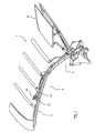
- Fig. 1 shows a half-page representation in whole with 1 folding top or its top frame in a movement phase shortly after the start the opening process or shortly before the end of Closing process
- the convertible top frame essentially three mutually movable or foldable roof parts has, namely a front roof part 2, a middle Roof part 4 and a rear roof part 6, and wherein additionally shown a rear window element 8 is.
- the folding roof is in stored a convertible top compartment, not shown, the with a convertible top compartment lid, also not shown is closed or covered.
- a pivot point (pivot axis) 10 pivotable with each other connected first 12 and second frame parts 14 have a folding movement of the roof parts 2 and 4 enable relative to each other.
- swivel connection 10 could also be act a different kind of kinematic connection, e.g. with superimposed translational movement of a frame part relative to another.
- FIG. 2 is a sectional view through the adjusting device to explain the individual components 3 and 4 show two movement states or Relative positions of the two frame parts 12 and 14 1, to which the whole with 16 designated setting device is assigned.
- FIGS. 2 to 4 shows an integration or local merging an attack with an associated query system.
- the stop is on the one hand with a sleeve 20 External thread formed on which a stop element 22nd is screwed on with a first stop surface 24, and on the other hand by a second stop surface 26, which is formed on the first frame part 12.
- the spatial fixation of the sleeve 20 on the second frame part 14 is carried out by means of a carrier plate 28 and Lock nuts 30 on the external thread of the sleeve 20 in such a way that when a desired relative position is reached between the frame parts 12, 14 in the sense of a End stop, the two stop surfaces 24, 26 with each other cooperate (Fig. 4) and pivoting about prevent the condition shown.
- the carrier plate 28 is with screws 32 on the second Frame part 14 fixed and could alternatively be welded on or attached in any other way. Also a position-adjustable fastening is conceivable.
- a detection device for detecting a specifiable Relative position between the two frame parts 12, 14 is initially a transmission link in the form of a Ram 34 guided longitudinally in the sleeve 20 provided, the front end portion 34a in the area of the stop element 22 from the sleeve 20 and over the Stop surface 24 protrudes.
- the said detection device also has Query system, in the present embodiment in Form of a microswitch 36 on, this by a rear end portion 34b of the plunger 34 is operable is.
- the microswitch 36 is also on the Sleeve 20 attached, by means of a carrier plate 38, that with two lock nuts 40 on the external thread the sleeve is fixed to be adjustable in length.
- the plunger 34 has an outer shoulder 35 (FIG. 2) and the sleeve 20 has an inner shoulder 21, whereby a Receiving space 42 for a compression spring (coil spring) 44 is formed, which the plunger towards the in 2 and 3 biased position shown.
- a compression spring coil spring
- the microswitch 36 is preferably of an appropriate type Sealing weatherproof or insensitive to moisture encased and, for example, with a plastic coating Mistake.
- the switching point can be on this Point to a desired point in the process before reaching it the stop position.
- the query system be, for example a reed contact, Hall sensors, inductive or capacitive indicators or a (fork) light barrier.
- a movable mechanical transmission element as in the present case of the plunger 34 is not essential is necessary, for example in one embodiment, in which a query system immediately in the Area of the attack, i.e. in the area of the stop surface 24 is arranged. Even in such an embodiment it is guaranteed that a recording of the Relative position immediately adjacent to the mechanical one Stop occurs and by adjusting the position of the Query system the switching point is adjustable.
Landscapes
- Engineering & Computer Science (AREA)
- Mechanical Engineering (AREA)
- Body Structure For Vehicles (AREA)
- Seal Device For Vehicle (AREA)
- Vehicle Body Suspensions (AREA)
- Fittings On The Vehicle Exterior For Carrying Loads, And Devices For Holding Or Mounting Articles (AREA)
- Electronic Switches (AREA)
Abstract
Description
Claims (19)
- Einstellvorrichtung für ein schwenkbares erstes Gestellteil (12) eines Cabriolet-Verdeckgestells (1), das über eine kinematische Anbindung mit einem zweiten benachbarten oder karosseriefesten Gestellteil (14) verbunden ist, mit einem in seiner wirksamen Länge einstellbaren Anschlag (24, 26), der ein Verschwenken des ersten Gestellteils (12) relativ zu dem zweiten Gestellteil (14) begrenzt, dadurch gekennzeichnet, daß dem Anschlag (24, 26) eine Erfassungseinrichtung (16) zum Erfassen einer vorgebbaren Relativposition zwischen dem ersten (12) und dem zweiten Gestellteil (14) zugeordnet ist.
- Einstellvorrichtung nach Anspruch 1, dadurch gekennzeichnet, daß die Erfassungseinrichtung (16) in oder unmittelbar benachbart zu dem Anschlag (24, 26) angeordnet ist.
- Einstellvorrichtung nach Anspruch 1 oder 2, dadurch gekennzeichnet, daß die Erfassungseinrichtung (16) mechanisch, elektrisch, elektromagnetisch und/oder optisch arbeitet.
- Einstellvorrichtung nach einem der vorangehenden Ansprüche, dadurch gekennzeichnet, daß die Erfassungseinrichtung einen Schalter, eine Lichtschranke oder einen induktiven oder kapazitiven Sensor, insbesondere Hall-Geber, aufweist.
- Einstellvorrichtung nach einem der vorangehenden Ansprüche, dadurch gekennzeichnet, daß die Erfassungseinrichtung (16) ein bewegliches mechanisches Übertragungsglied (34) aufweist.
- Einstellvorrichtung nach Anspruch 5, dadurch gekennzeichnet, daß die Erfassungseinrichtung (16) eine Abfrageeinrichtung (36) aufweist, mit der das Übertragungsglied (34) zusammenwirkt und in der bei Erreichen der vorgegebenen Relativposition ein Schaltvorgang ausgelöst wird.
- Erfassungsvorrichtung nach einem der vorangehenden Ansprüche, dadurch gekennzeichnet, daß das Übertragungsglied als federbelasteter Stößel (34) ausgebildet ist.
- Einstellvorrichtung nach Anspruch 6 oder 7, dadurch gekennzeichnet, daß Anschlag (24), Übertragungsglied (34) und Abfrageeinrichtung (36) eine Baueinheit (16) bilden.
- Einstellvorrichtung nach einem der vorangehenden Ansprüche, dadurch gekennzeichnet, daß der Anschlag eine mit Außengewinde versehene Hülse (20) aufweist.
- Einstellvorrichtung nach einem der vorangehenden Ansprüche, dadurch gekennzeichnet, daß der Anschlag ein separates Anschlagelement (22) aufweist.
- Einstellvorrichtung nach einem der vorangehenden Ansprüche, dadurch gekennzeichnet, daß der Anschlag zur Einstellung seiner wirksamen Länge in veränderbarer Lage fixierbar ist, insbesondere mittels Kontermuttern (28).
- Einstellvorrichtung nach einem der Ansprüche 5 bis 11, dadurch gekennzeichnet, daß das Übertragungsglied (34) konzentrisch innerhalb des Anschlags (24) angeordnet ist.
- Einstellvorrichtung nach einem der Ansprüche 9 bis 12, dadurch gekennzeichnet, daß das Übertragungsglied (34) konzentrisch innerhalb der Hülse (20) angeordnet ist.
- Einstellvorrichtung nach einem der Ansprüche 6 bis 13, dadurch gekennzeichnet, daß die Abfrageeinrichtung ein Schaltelement (36) und ein das Schaltelement (36) aufnehmendes Trägerblech (38) aufweist.
- Einstellvorrichtung nach Anspruch 14, dadurch gekennzeichnet, daß Trägerblech (38) und Schaltelement (36) mit einer feuchtigkeitsdichten Kapselung, insbesondere Kunststoffkapselung, versehen sind.
- Einstellvorrichtung nach einem der Ansprüche 9 bis 15, dadurch gekennzeichnet, daß die Abfrageeinrichtung (36) auf der Hülse (20) lageveränderlich fixierbar ist, insbesondere mittels Kontermuttern (40).
- Einstellvorrichtung nach einem der Ansprüche 6 bis 16, dadurch gekennzeichnet, daß die Abfrageeinrichtung ein Mikroschalter (36) ist.
- Einstellvorrichtung nach einem der Ansprüche 6 bis 16, dadurch gekennzeichnet, daß das Schaltelement ein Reedkontakt, ein Hall-Geber, ein induktiver oder kapazitiver Sensor oder eine (Gabel-)Lichtschranke ist.
- Verdeckgestell mit mindestens einer Einstellvorrichtung nach einem der vorangehenden Ansprüche.
Applications Claiming Priority (2)
| Application Number | Priority Date | Filing Date | Title |
|---|---|---|---|
| DE20117926U | 2001-11-03 | ||
| DE20117926U DE20117926U1 (de) | 2001-11-03 | 2001-11-03 | Einstellvorrichtung für ein Verdeckgestell |
Publications (2)
| Publication Number | Publication Date |
|---|---|
| EP1308332A1 true EP1308332A1 (de) | 2003-05-07 |
| EP1308332B1 EP1308332B1 (de) | 2006-12-20 |
Family
ID=7963561
Family Applications (1)
| Application Number | Title | Priority Date | Filing Date |
|---|---|---|---|
| EP02024099A Expired - Lifetime EP1308332B1 (de) | 2001-11-03 | 2002-10-29 | Einstellvorrichtung für ein Cabriolet-Verdeckgestell |
Country Status (3)
| Country | Link |
|---|---|
| EP (1) | EP1308332B1 (de) |
| AT (1) | ATE348724T1 (de) |
| DE (2) | DE20117926U1 (de) |
Families Citing this family (5)
| Publication number | Priority date | Publication date | Assignee | Title |
|---|---|---|---|---|
| DE102006030517A1 (de) * | 2006-07-01 | 2008-01-03 | Wilhelm Karmann Gmbh | Cabriolet-Fahrzeug mit einem Dach mit mehreren seitlichen Rahmenteilen |
| DE102009042236A1 (de) * | 2009-09-18 | 2011-03-31 | Magna Car Top Systems Gmbh | Faltverdeck für einen Personenkraftwagen |
| DE102010007731A1 (de) * | 2010-02-12 | 2011-08-18 | Magna Car Top Systems GmbH, 74321 | Sturmstangeneinrichtung für ein Faltverdeck |
| DE102018202986B4 (de) | 2018-02-28 | 2022-02-03 | Magna Car Top Systems Gmbh | Anschlagschraube einer Verdeckkinematik eines Faltverdecks für ein Kraftfahrzeug, sowie Verfahren zum Einstellen eines Anschlages mit einer solchen |
| DE102018113457A1 (de) * | 2018-06-06 | 2019-12-12 | Dr. Ing. H.C. F. Porsche Aktiengesellschaft | Scharniervorrichtung für ein bewegbares Fahrzeugdach eines Fahrzeugs |
Citations (5)
| Publication number | Priority date | Publication date | Assignee | Title |
|---|---|---|---|---|
| DE3914638A1 (de) * | 1989-05-03 | 1990-11-08 | Scharwaechter Gmbh Co Kg | Klappverdeck fuer kraftfahrzeuge |
| DE4121226C1 (de) * | 1991-06-27 | 1992-05-27 | Mercedes-Benz Aktiengesellschaft, 7000 Stuttgart, De | |
| DE4128542C1 (en) * | 1991-08-28 | 1992-08-27 | Mercedes-Benz Aktiengesellschaft, 7000 Stuttgart, De | Adjuster for foldable top swivelling frame member - has support with threaded bolt securable at variable length at frame member |
| DE19525292A1 (de) * | 1995-07-03 | 1997-01-09 | Brose Fahrzeugteile | Vorrichtung zur Erfassung des Drehwinkels, der Drehzahl und/oder der Drehrichtung eines Drehantriebes |
| EP0930187A2 (de) * | 1998-01-20 | 1999-07-21 | CTS Fahrzeug-Dachsysteme GmbH | Verriegelungseinrichtung zum Festlegen eines Verdecks |
Family Cites Families (3)
| Publication number | Priority date | Publication date | Assignee | Title |
|---|---|---|---|---|
| AT405156B (de) | 1997-11-21 | 1999-06-25 | Hoerbiger Gmbh | Steuersystem für ein verdeck, insbesonders für fahrzeuge |
| DE19808588A1 (de) | 1998-02-28 | 1999-09-02 | Edscha Cabrio Verdecksys Gmbh | Sicherheitseinrichtung für Faltverdecke an Kraftwagen |
| US5998948A (en) | 1998-05-29 | 1999-12-07 | Acs Incorporated | Convertible roof actuation mechanism |
-
2001
- 2001-11-03 DE DE20117926U patent/DE20117926U1/de not_active Expired - Lifetime
-
2002
- 2002-10-29 AT AT02024099T patent/ATE348724T1/de not_active IP Right Cessation
- 2002-10-29 DE DE50208998T patent/DE50208998D1/de not_active Expired - Lifetime
- 2002-10-29 EP EP02024099A patent/EP1308332B1/de not_active Expired - Lifetime
Patent Citations (5)
| Publication number | Priority date | Publication date | Assignee | Title |
|---|---|---|---|---|
| DE3914638A1 (de) * | 1989-05-03 | 1990-11-08 | Scharwaechter Gmbh Co Kg | Klappverdeck fuer kraftfahrzeuge |
| DE4121226C1 (de) * | 1991-06-27 | 1992-05-27 | Mercedes-Benz Aktiengesellschaft, 7000 Stuttgart, De | |
| DE4128542C1 (en) * | 1991-08-28 | 1992-08-27 | Mercedes-Benz Aktiengesellschaft, 7000 Stuttgart, De | Adjuster for foldable top swivelling frame member - has support with threaded bolt securable at variable length at frame member |
| DE19525292A1 (de) * | 1995-07-03 | 1997-01-09 | Brose Fahrzeugteile | Vorrichtung zur Erfassung des Drehwinkels, der Drehzahl und/oder der Drehrichtung eines Drehantriebes |
| EP0930187A2 (de) * | 1998-01-20 | 1999-07-21 | CTS Fahrzeug-Dachsysteme GmbH | Verriegelungseinrichtung zum Festlegen eines Verdecks |
Also Published As
| Publication number | Publication date |
|---|---|
| DE20117926U1 (de) | 2002-01-17 |
| ATE348724T1 (de) | 2007-01-15 |
| EP1308332B1 (de) | 2006-12-20 |
| DE50208998D1 (de) | 2007-02-01 |
Similar Documents
| Publication | Publication Date | Title |
|---|---|---|
| DE69727712T2 (de) | Griff für eine Bedienungsvorrichtung zum Öffnen eines Kraftfahrzeugtürschlosses | |
| EP1840014B1 (de) | Luftleitvorrichtung für ein Fahrzeug | |
| WO2011141485A1 (de) | Griffvorrichtung insbesondere für ein fahrzeug | |
| EP0760304A1 (de) | Verdeck für ein Fahrzeug, insbesondere Personenkraftwagen | |
| DE3715268A1 (de) | Betaetigungsvorrichtung fuer ein fahrzeugdach | |
| DE10043931B4 (de) | Haubenscharnier | |
| EP1177942B1 (de) | Rückstelleinrichtung für einen Schalter eines Kraftfahrzeuges | |
| DE19611222C2 (de) | Ausstellmechanismus | |
| WO1996023338A2 (de) | Vorrichtung zur beeinflussung eines fahrantriebes eines schaltgerätes | |
| EP1308332B1 (de) | Einstellvorrichtung für ein Cabriolet-Verdeckgestell | |
| EP0803140B1 (de) | Einschubrahmen mit einer trennkontaktanordnung | |
| DE2815888C2 (de) | Druckabhängiger Schalter | |
| DE19719999A1 (de) | Verschluß für Öffnungseinrichtung in Fahrzeugen | |
| EP0197025B1 (de) | Notbetätigungseinrichtung für grifflose Türverriegelungen | |
| DE10319743B4 (de) | Kraftfahrzeugschloß mit elektrischem Öffnungsantrieb | |
| EP1860262A2 (de) | Verriegelungsvorrichtung für eine Fahrzeugtür | |
| EP0328945B1 (de) | Türschliesser | |
| DE10052442C2 (de) | Stellvorrichtung für ein Fahrzeug mit einem mechanisch verstellbaren Bauteil und Verfahren zum Betreiben der Stellvorrichtung | |
| DE19840060B4 (de) | Dreh-Druck-Schalter für eine Fahrzeugkomponente, insbesondere für eine Fahrzeuginnenraum-Heizungs- oder Klimaanlage | |
| EP0846828B1 (de) | Vorrichtung zur Regelung der Schliessfolge von zweiflügeligen Türen | |
| EP0122325A2 (de) | Vorrichtung zum automatischen Rücköffnen von mit Drehsäulen betätigten Schwingtüren oder Schiebetüren bei Fahrzeugen | |
| DE10030275B4 (de) | Rastmechanismus für einen Fahrtrichtungsschalter eines Kraftfahrzeugs | |
| DE102004054160B4 (de) | Verdeck für ein Cabriolet-Fahrzeug | |
| DE4222798A1 (de) | Baugruppe aus einem Schloß und einem Stellelement | |
| EP1323883A2 (de) | Kraftfahrzeugtürverschluss |
Legal Events
| Date | Code | Title | Description |
|---|---|---|---|
| PUAI | Public reference made under article 153(3) epc to a published international application that has entered the european phase |
Free format text: ORIGINAL CODE: 0009012 |
|
| AK | Designated contracting states |
Designated state(s): AT BE BG CH CY CZ DE DK EE ES FI FR GB GR IE IT LI LU MC NL PT SE SK TR |
|
| AX | Request for extension of the european patent |
Extension state: AL LT LV MK RO SI |
|
| 17P | Request for examination filed |
Effective date: 20030528 |
|
| AKX | Designation fees paid |
Designated state(s): AT BE BG CH CY CZ DE DK EE ES FI FR GB GR IE IT LI LU MC NL PT SE SK TR |
|
| GRAP | Despatch of communication of intention to grant a patent |
Free format text: ORIGINAL CODE: EPIDOSNIGR1 |
|
| GRAS | Grant fee paid |
Free format text: ORIGINAL CODE: EPIDOSNIGR3 |
|
| GRAA | (expected) grant |
Free format text: ORIGINAL CODE: 0009210 |
|
| AK | Designated contracting states |
Kind code of ref document: B1 Designated state(s): AT BE BG CH CY CZ DE DK EE ES FI FR GB GR IE IT LI LU MC NL PT SE SK TR |
|
| PG25 | Lapsed in a contracting state [announced via postgrant information from national office to epo] |
Ref country code: IE Free format text: LAPSE BECAUSE OF FAILURE TO SUBMIT A TRANSLATION OF THE DESCRIPTION OR TO PAY THE FEE WITHIN THE PRESCRIBED TIME-LIMIT Effective date: 20061220 Ref country code: CZ Free format text: LAPSE BECAUSE OF FAILURE TO SUBMIT A TRANSLATION OF THE DESCRIPTION OR TO PAY THE FEE WITHIN THE PRESCRIBED TIME-LIMIT Effective date: 20061220 Ref country code: SK Free format text: LAPSE BECAUSE OF FAILURE TO SUBMIT A TRANSLATION OF THE DESCRIPTION OR TO PAY THE FEE WITHIN THE PRESCRIBED TIME-LIMIT Effective date: 20061220 Ref country code: FI Free format text: LAPSE BECAUSE OF FAILURE TO SUBMIT A TRANSLATION OF THE DESCRIPTION OR TO PAY THE FEE WITHIN THE PRESCRIBED TIME-LIMIT Effective date: 20061220 Ref country code: NL Free format text: LAPSE BECAUSE OF FAILURE TO SUBMIT A TRANSLATION OF THE DESCRIPTION OR TO PAY THE FEE WITHIN THE PRESCRIBED TIME-LIMIT Effective date: 20061220 Ref country code: DK Free format text: LAPSE BECAUSE OF FAILURE TO SUBMIT A TRANSLATION OF THE DESCRIPTION OR TO PAY THE FEE WITHIN THE PRESCRIBED TIME-LIMIT Effective date: 20061220 |
|
| REG | Reference to a national code |
Ref country code: GB Ref legal event code: FG4D Free format text: NOT ENGLISH |
|
| REG | Reference to a national code |
Ref country code: CH Ref legal event code: EP |
|
| REF | Corresponds to: |
Ref document number: 50208998 Country of ref document: DE Date of ref document: 20070201 Kind code of ref document: P |
|
| REG | Reference to a national code |
Ref country code: IE Ref legal event code: FG4D Free format text: LANGUAGE OF EP DOCUMENT: GERMAN |
|
| PG25 | Lapsed in a contracting state [announced via postgrant information from national office to epo] |
Ref country code: BG Free format text: LAPSE BECAUSE OF FAILURE TO SUBMIT A TRANSLATION OF THE DESCRIPTION OR TO PAY THE FEE WITHIN THE PRESCRIBED TIME-LIMIT Effective date: 20070320 Ref country code: SE Free format text: LAPSE BECAUSE OF FAILURE TO SUBMIT A TRANSLATION OF THE DESCRIPTION OR TO PAY THE FEE WITHIN THE PRESCRIBED TIME-LIMIT Effective date: 20070320 |
|
| PG25 | Lapsed in a contracting state [announced via postgrant information from national office to epo] |
Ref country code: ES Free format text: LAPSE BECAUSE OF FAILURE TO SUBMIT A TRANSLATION OF THE DESCRIPTION OR TO PAY THE FEE WITHIN THE PRESCRIBED TIME-LIMIT Effective date: 20070331 |
|
| GBT | Gb: translation of ep patent filed (gb section 77(6)(a)/1977) |
Effective date: 20070320 |
|
| PG25 | Lapsed in a contracting state [announced via postgrant information from national office to epo] |
Ref country code: PT Free format text: LAPSE BECAUSE OF FAILURE TO SUBMIT A TRANSLATION OF THE DESCRIPTION OR TO PAY THE FEE WITHIN THE PRESCRIBED TIME-LIMIT Effective date: 20070423 |
|
| NLV1 | Nl: lapsed or annulled due to failure to fulfill the requirements of art. 29p and 29m of the patents act | ||
| ET | Fr: translation filed | ||
| PLBE | No opposition filed within time limit |
Free format text: ORIGINAL CODE: 0009261 |
|
| STAA | Information on the status of an ep patent application or granted ep patent |
Free format text: STATUS: NO OPPOSITION FILED WITHIN TIME LIMIT |
|
| 26N | No opposition filed |
Effective date: 20070921 |
|
| BERE | Be: lapsed |
Owner name: WILHELM KARMANN G.M.B.H. Effective date: 20071031 |
|
| PG25 | Lapsed in a contracting state [announced via postgrant information from national office to epo] |
Ref country code: GR Free format text: LAPSE BECAUSE OF FAILURE TO SUBMIT A TRANSLATION OF THE DESCRIPTION OR TO PAY THE FEE WITHIN THE PRESCRIBED TIME-LIMIT Effective date: 20070321 |
|
| PG25 | Lapsed in a contracting state [announced via postgrant information from national office to epo] |
Ref country code: MC Free format text: LAPSE BECAUSE OF NON-PAYMENT OF DUE FEES Effective date: 20071031 |
|
| REG | Reference to a national code |
Ref country code: CH Ref legal event code: PL |
|
| PG25 | Lapsed in a contracting state [announced via postgrant information from national office to epo] |
Ref country code: CH Free format text: LAPSE BECAUSE OF NON-PAYMENT OF DUE FEES Effective date: 20071031 Ref country code: LI Free format text: LAPSE BECAUSE OF NON-PAYMENT OF DUE FEES Effective date: 20071031 |
|
| PG25 | Lapsed in a contracting state [announced via postgrant information from national office to epo] |
Ref country code: BE Free format text: LAPSE BECAUSE OF NON-PAYMENT OF DUE FEES Effective date: 20071031 |
|
| PG25 | Lapsed in a contracting state [announced via postgrant information from national office to epo] |
Ref country code: EE Free format text: LAPSE BECAUSE OF FAILURE TO SUBMIT A TRANSLATION OF THE DESCRIPTION OR TO PAY THE FEE WITHIN THE PRESCRIBED TIME-LIMIT Effective date: 20061220 |
|
| PG25 | Lapsed in a contracting state [announced via postgrant information from national office to epo] |
Ref country code: AT Free format text: LAPSE BECAUSE OF NON-PAYMENT OF DUE FEES Effective date: 20071029 |
|
| PG25 | Lapsed in a contracting state [announced via postgrant information from national office to epo] |
Ref country code: LU Free format text: LAPSE BECAUSE OF NON-PAYMENT OF DUE FEES Effective date: 20071029 Ref country code: CY Free format text: LAPSE BECAUSE OF FAILURE TO SUBMIT A TRANSLATION OF THE DESCRIPTION OR TO PAY THE FEE WITHIN THE PRESCRIBED TIME-LIMIT Effective date: 20061220 |
|
| PG25 | Lapsed in a contracting state [announced via postgrant information from national office to epo] |
Ref country code: TR Free format text: LAPSE BECAUSE OF FAILURE TO SUBMIT A TRANSLATION OF THE DESCRIPTION OR TO PAY THE FEE WITHIN THE PRESCRIBED TIME-LIMIT Effective date: 20061220 |
|
| PGFP | Annual fee paid to national office [announced via postgrant information from national office to epo] |
Ref country code: IT Payment date: 20101022 Year of fee payment: 9 |
|
| PG25 | Lapsed in a contracting state [announced via postgrant information from national office to epo] |
Ref country code: IT Free format text: LAPSE BECAUSE OF NON-PAYMENT OF DUE FEES Effective date: 20111029 |
|
| REG | Reference to a national code |
Ref country code: GB Ref legal event code: 732E Free format text: REGISTERED BETWEEN 20131114 AND 20131120 |
|
| REG | Reference to a national code |
Ref country code: FR Ref legal event code: TP Owner name: VALMET AUTOMOTIVE OY, FI Effective date: 20131209 |
|
| REG | Reference to a national code |
Ref country code: DE Ref legal event code: R082 Ref document number: 50208998 Country of ref document: DE Representative=s name: KRONTHALER, SCHMIDT & COLL. PATENTANWALTSKANZL, DE Effective date: 20131128 Ref country code: DE Ref legal event code: R081 Ref document number: 50208998 Country of ref document: DE Owner name: VALMET AUTOMOTIVE OY, FI Free format text: FORMER OWNER: WILHELM KARMANN GMBH, 49084 OSNABRUECK, DE Effective date: 20131128 |
|
| PGFP | Annual fee paid to national office [announced via postgrant information from national office to epo] |
Ref country code: FR Payment date: 20131018 Year of fee payment: 12 Ref country code: GB Payment date: 20131022 Year of fee payment: 12 |
|
| PGFP | Annual fee paid to national office [announced via postgrant information from national office to epo] |
Ref country code: DE Payment date: 20141120 Year of fee payment: 13 |
|
| GBPC | Gb: european patent ceased through non-payment of renewal fee |
Effective date: 20141029 |
|
| PG25 | Lapsed in a contracting state [announced via postgrant information from national office to epo] |
Ref country code: GB Free format text: LAPSE BECAUSE OF NON-PAYMENT OF DUE FEES Effective date: 20141029 |
|
| REG | Reference to a national code |
Ref country code: FR Ref legal event code: ST Effective date: 20150630 |
|
| PG25 | Lapsed in a contracting state [announced via postgrant information from national office to epo] |
Ref country code: FR Free format text: LAPSE BECAUSE OF NON-PAYMENT OF DUE FEES Effective date: 20141031 |
|
| REG | Reference to a national code |
Ref country code: DE Ref legal event code: R119 Ref document number: 50208998 Country of ref document: DE |
|
| PG25 | Lapsed in a contracting state [announced via postgrant information from national office to epo] |
Ref country code: DE Free format text: LAPSE BECAUSE OF NON-PAYMENT OF DUE FEES Effective date: 20160503 |