EP1306268A1 - Dichtungsband mit Dichtungsfuss - Google Patents
Dichtungsband mit Dichtungsfuss Download PDFInfo
- Publication number
- EP1306268A1 EP1306268A1 EP02023429A EP02023429A EP1306268A1 EP 1306268 A1 EP1306268 A1 EP 1306268A1 EP 02023429 A EP02023429 A EP 02023429A EP 02023429 A EP02023429 A EP 02023429A EP 1306268 A1 EP1306268 A1 EP 1306268A1
- Authority
- EP
- European Patent Office
- Prior art keywords
- sealing
- lips
- sealing tape
- channel
- foot
- Prior art date
- Legal status (The legal status is an assumption and is not a legal conclusion. Google has not performed a legal analysis and makes no representation as to the accuracy of the status listed.)
- Granted
Links
- 238000007789 sealing Methods 0.000 title claims abstract description 69
- 238000003780 insertion Methods 0.000 claims description 4
- 230000037431 insertion Effects 0.000 claims description 4
- 229920002943 EPDM rubber Polymers 0.000 claims description 3
- 230000001419 dependent effect Effects 0.000 description 1
- 238000009434 installation Methods 0.000 description 1
- 238000004519 manufacturing process Methods 0.000 description 1
- 239000000463 material Substances 0.000 description 1
- 238000005457 optimization Methods 0.000 description 1
- 239000002699 waste material Substances 0.000 description 1
Images
Classifications
-
- B—PERFORMING OPERATIONS; TRANSPORTING
- B60—VEHICLES IN GENERAL
- B60R—VEHICLES, VEHICLE FITTINGS, OR VEHICLE PARTS, NOT OTHERWISE PROVIDED FOR
- B60R13/00—Elements for body-finishing, identifying, or decorating; Arrangements or adaptations for advertising purposes
- B60R13/06—Sealing strips
-
- B—PERFORMING OPERATIONS; TRANSPORTING
- B60—VEHICLES IN GENERAL
- B60J—WINDOWS, WINDSCREENS, NON-FIXED ROOFS, DOORS, OR SIMILAR DEVICES FOR VEHICLES; REMOVABLE EXTERNAL PROTECTIVE COVERINGS SPECIALLY ADAPTED FOR VEHICLES
- B60J10/00—Sealing arrangements
- B60J10/30—Sealing arrangements characterised by the fastening means
Definitions
- the invention relates to a sealing tape with a sealing foot for insertion into one U-shaped channel according to the preamble of claims 1 and 2.
- Sealing tapes with a sealing foot which is in a U-shaped are generally known Channel can be inserted.
- the U-shaped channel can - in cross section seen - one each at the free ends of the sides on the inside Have a head start. So that the sealing foot as well as possible in the U-shaped Channel is held, it has one on both sides at its free lower end elastic locking lip, which in the installed state in the channel Engages behind projections. Disadvantages lead to tolerances of the sealing tape and / or the channel again and again to a difficult assembly or to one insufficient locking of the locking lips on the projections.
- the object of the invention is to provide the known sealing tape with a sealing foot Insert into a U-shaped channel so that it is also at occurring tolerances is easy to assemble and still a tight fit in the Channel guaranteed.
- the sealing tape is advantageously made of EPDM.
- EPDM is a common inexpensive material from which sealing tapes are easily extruded can. The tool costs required for this are low.
- the locking lips and / or the counterforce lips and / or the lateral ones Guide lips can advantageously not only over the entire length of the Sealing tape extend, but only on certain areas of the Sealing tape. As a result, the installation radii of the Sealing tape possible.
- the latching, counterforce and lateral Guide lips make it difficult to install the seal in small radii.
- That Sealing tape for example in the radius area, no locking lips and / or Have counterforce lips and / or lateral guide lips.
- the sealing tape is attached to the Radius area adjacent areas is held securely.
- the locking lips and / or counterforce lips and / or lateral Guide lips designed as lugs without any significant longitudinal extension. Several such attachment points are also sufficient for attachment and thus enable the sealing tape to be laid very freely.
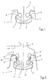
- a bumper strip 1 is shown in cross section on a passenger car, which has a U-shaped channel 2.
- a sealing tape 3 with a sealing foot 4 known from the prior art is inserted into the U-shaped channel 2.
- a locking lip 5 is attached on both sides. These locking lips 5 are hooked in the channel 2 on projections 6, which are attached to the inside of the free ends of the sides of the channel 2. As a result, the sealing tape 3 is held securely in the channel 2.
- the sealing tape 3 ' is also in a U-shaped channel 2' of a bumper 1 ' a passenger car with a sealing foot 4 'inserted.
- a locking lip 5' on both sides appropriate.
- These latching lips 5 'hook into projections in the channel 2' 6 'attached to the inside of the free ends of the sides of the channel 2' are.
- These counterforce lips 7 ' press on the channel 2' from the outside. she bring a counterforce to the locking lips 5 '.
- the Locking lips 5 ' Together with the Locking lips 5 'represent a resilient element Sealing foot 4 'floating in height. In this way, the Compensate for height tolerances of the sealing tape 3 'and the channel 2'.
- Sealing foot 4 'each have a lateral guide lip 8' attached.
- This side Guide lips 8 ' guide the sealing foot 4' in the middle of the channel during assembly 2 'a. In this way, for example, one for the rear locking Locking lips 5 'critical tilting of the sealing foot 4' during assembly prevented.
- the lateral guide lips 8 ' compensate for width tolerances the sealing tape 3 'and / or the channel 2'.
Landscapes
- Engineering & Computer Science (AREA)
- Mechanical Engineering (AREA)
- Seal Device For Vehicle (AREA)
- Joints With Pressure Members (AREA)
- Orthopedics, Nursing, And Contraception (AREA)
Abstract
Description
- Fig. 1
- einen Schnitt durch ein aus dem Stand der Technik bekanntes Dichtungsband, das in einen Kanal eingesteckt ist und
- Fig. 2
- einen Schnitt durch ein erfindungsgemäßes Dichtungsband, das in einen Kanal eingesteckt ist.
Claims (6)
- Dichtungsband mit Dichtungsfuß zum Einstecken in einen U-förmigen Kanal, an dessen freien Enden der Seiten im Querschnitt gesehen sich innen jeweils ein Vorsprung befindet, wobei der Dichtungsfuß am unteren Ende beidseitig je eine elastische Verrastungslippe aufweist, die im eingebauten Zustand im Kanal die Vorsprünge hintergreift, dadurch gekennzeichnet, dass oberhalb der beiden Verrastungslippen (5') beidseitig eine Gegenkraftlippe (7') am Dichtungsfuß (4') oder am Dichtungsband (3') angebracht ist, die im eingebauten Zustand von außen auf den Kanal (2') drückt.
- Dichtungsband mit Dichtungsfuß zum Einstecken in einen U-förmigen Kanal, an dessen freien Enden der Seiten im Querschnitt gesehen sich innen jeweils ein Vorsprung befindet, wobei der Dichtungsfuß am unteren Ende beidseitig je eine elastische Verrastungslippe aufweist, die im eingebauten Zustand im Kanal die Vorsprünge hintergreift, dadurch gekennzeichnet, dass oberhalb der beiden Verrastungslippen (5') beidseitig zumindest jeweils eine seitliche Führungslippe (8') am Dichtungsfuß (4') angebracht ist, die sich im eingebauten Zustand an den Vorsprung (6') anlehnt.
- Dichtungsband nach Anspruch 1 und / oder 2, dadurch gekennzeichnet, dass das Dichtungsband (2') aus EPDM besteht.
- Dichtungsband nach mindestens einem der vorhergehenden Ansprüche, dadurch gekennzeichnet, dass die Verrastungslippen (5') und / oder die Gegenkraftlippen (7') und / oder die seitlichen Führungslippen (8') sich nicht über die ganze Länge des Dichtungsbands (2') erstrecken, sondern sich nur an bestimmten Bereichen des Dichtungsbands (2') befinden..
- Dichtungsband nach Anspruch 4, dadurch gekennzeichnet, dass die Verrastungslippen (5') und / oder die Gegenkraftlippen (7') und / oder die seitlichen Führungslippen (8') als Nasen ohne nennenswerte Längserstreckung ausgeführt sind.
- Dichtungsband nach mindestens einem der vorhergehenden Ansprüche, dadurch gekennzeichnet, dass das Dichtungsband (2') für eine Anwendung an einem Kraftfahrzeug konzipiert ist.
Applications Claiming Priority (2)
| Application Number | Priority Date | Filing Date | Title |
|---|---|---|---|
| DE10153135 | 2001-10-27 | ||
| DE10153135A DE10153135A1 (de) | 2001-10-27 | 2001-10-27 | Dichtungsband mit Dichtungsfuß |
Publications (2)
| Publication Number | Publication Date |
|---|---|
| EP1306268A1 true EP1306268A1 (de) | 2003-05-02 |
| EP1306268B1 EP1306268B1 (de) | 2006-03-01 |
Family
ID=7703963
Family Applications (1)
| Application Number | Title | Priority Date | Filing Date |
|---|---|---|---|
| EP02023429A Expired - Lifetime EP1306268B1 (de) | 2001-10-27 | 2002-10-19 | Dichtungsband mit Dichtungsfuss |
Country Status (2)
| Country | Link |
|---|---|
| EP (1) | EP1306268B1 (de) |
| DE (2) | DE10153135A1 (de) |
Families Citing this family (1)
| Publication number | Priority date | Publication date | Assignee | Title |
|---|---|---|---|---|
| DE102019126996A1 (de) | 2019-10-08 | 2021-04-08 | Webasto SE | Dichtungssteckprofil, Anordnung für ein Fahrzeugdach und Fahrzeugdach für ein Kraftfahrzeug |
Citations (6)
| Publication number | Priority date | Publication date | Assignee | Title |
|---|---|---|---|---|
| JPH1076886A (ja) * | 1996-09-06 | 1998-03-24 | Suzuki Motor Corp | 自動車のルーフモール取付構造 |
| JPH10109600A (ja) * | 1996-10-04 | 1998-04-28 | Toyota Motor Corp | 自動車のルーフモール |
| JPH11165596A (ja) * | 1997-12-03 | 1999-06-22 | Toyoda Gosei Co Ltd | 車両用ルーフモール |
| JPH11291836A (ja) * | 1998-04-08 | 1999-10-26 | Katayama Kogyo Kk | 車両用ルーフモールディング |
| JP2001199286A (ja) * | 2000-01-18 | 2001-07-24 | Inoac Corp | 車両用ルーフモール |
| JP2001354078A (ja) * | 2000-06-12 | 2001-12-25 | Shiroki Corp | ドリップモール、及びモール |
Family Cites Families (7)
| Publication number | Priority date | Publication date | Assignee | Title |
|---|---|---|---|---|
| CH406592A (de) * | 1962-10-05 | 1966-01-31 | Kuentz Alphons | Dichtungsstreifen aus gummi-elastischem Material |
| US3378957A (en) * | 1966-02-23 | 1968-04-23 | Gen Tire & Rubber Co | Gasket assembly |
| DE3629865A1 (de) * | 1986-09-02 | 1988-03-10 | Pirelli Reifenwerke | Strangfoermiges dichtungsprofil |
| DE19640041C2 (de) * | 1996-09-30 | 2000-07-27 | Saar Gummiwerk Gmbh | Umlaufende Glas-/Anschlagdichtung |
| JP3715400B2 (ja) * | 1997-02-13 | 2005-11-09 | 西川ゴム工業株式会社 | ドア用ウェザーストリップ |
| FR2786241B1 (fr) * | 1998-11-20 | 2001-05-11 | Rehau Sa | Joint profile, notamment pour chassis de fenetre, s'opposant au vent |
| DE10043136B4 (de) * | 2000-08-31 | 2013-08-01 | Webasto Ag | Dichtungsprofil, insbesondere für eine Schiebedachdichtung |
-
2001
- 2001-10-27 DE DE10153135A patent/DE10153135A1/de not_active Withdrawn
-
2002
- 2002-10-19 EP EP02023429A patent/EP1306268B1/de not_active Expired - Lifetime
- 2002-10-19 DE DE50205919T patent/DE50205919D1/de not_active Expired - Lifetime
Patent Citations (6)
| Publication number | Priority date | Publication date | Assignee | Title |
|---|---|---|---|---|
| JPH1076886A (ja) * | 1996-09-06 | 1998-03-24 | Suzuki Motor Corp | 自動車のルーフモール取付構造 |
| JPH10109600A (ja) * | 1996-10-04 | 1998-04-28 | Toyota Motor Corp | 自動車のルーフモール |
| JPH11165596A (ja) * | 1997-12-03 | 1999-06-22 | Toyoda Gosei Co Ltd | 車両用ルーフモール |
| JPH11291836A (ja) * | 1998-04-08 | 1999-10-26 | Katayama Kogyo Kk | 車両用ルーフモールディング |
| JP2001199286A (ja) * | 2000-01-18 | 2001-07-24 | Inoac Corp | 車両用ルーフモール |
| JP2001354078A (ja) * | 2000-06-12 | 2001-12-25 | Shiroki Corp | ドリップモール、及びモール |
Non-Patent Citations (6)
| Title |
|---|
| PATENT ABSTRACTS OF JAPAN vol. 1998, no. 08 30 June 1998 (1998-06-30) * |
| PATENT ABSTRACTS OF JAPAN vol. 1998, no. 09 31 July 1998 (1998-07-31) * |
| PATENT ABSTRACTS OF JAPAN vol. 1999, no. 11 30 September 1999 (1999-09-30) * |
| PATENT ABSTRACTS OF JAPAN vol. 2000, no. 01 31 January 2000 (2000-01-31) * |
| PATENT ABSTRACTS OF JAPAN vol. 2000, no. 24 11 May 2001 (2001-05-11) * |
| PATENT ABSTRACTS OF JAPAN vol. 2002, no. 04 4 August 2002 (2002-08-04) * |
Also Published As
| Publication number | Publication date |
|---|---|
| EP1306268B1 (de) | 2006-03-01 |
| DE50205919D1 (de) | 2006-04-27 |
| DE10153135A1 (de) | 2003-05-08 |
Similar Documents
| Publication | Publication Date | Title |
|---|---|---|
| DE69500485T2 (de) | Scheibenwischerblatt mit verbessertem mittel zum fixieren der versteifungsleiste in längsrichtung | |
| DE3513762C2 (de) | ||
| EP1636439A1 (de) | Oberflächenentwässerungseinrichtung | |
| DE3936260A1 (de) | Tuer- bzw. fensterdichtung fuer kraftfahrzeuge | |
| DE3306016C2 (de) | Flexible Befestigungsleiste für Fensterscheiben | |
| DE20111650U1 (de) | Fahrzeugdach mit mindestens zwei festen Dachteilen | |
| DE69106650T2 (de) | Elastomerisches Profil mit einem rohrförmigen Element und einem verstellbaren Querschnitt ausgestattet. | |
| DE19911450B4 (de) | Konstruktion zur Installierung eines Armaturenbretts | |
| DE19540413C1 (de) | Rahmen eines öffnungsfähigen Fahrzeugdaches | |
| DE102022111445B4 (de) | Kraftfahrzeugrohbau mit einem Dichtungsbauteil für einen Fensterschacht | |
| DE102019216483A1 (de) | Zierleiste und Steckverbindung für eine Kraftfahrzeugkarosserie | |
| DE10116456A1 (de) | Dachmodul für ein Fahrzeug | |
| DE9201801U1 (de) | Schubkasten mit einer Stützreling | |
| DE102005012018B4 (de) | Anschlag zur Begrenzung des Stellweges einer Längsverstellvorrichtung für Sitze | |
| EP1306268A1 (de) | Dichtungsband mit Dichtungsfuss | |
| DE9201119U1 (de) | Waschvorrichtung für die Windschutzscheibe eines Kraftfahrzeuges | |
| DE3910257C1 (de) | Personenkraftwagen | |
| DE2053086A1 (de) | Starres Schiebedach fur Fahrzeuge | |
| DE19623336C2 (de) | Abdeckvorrichtung zum Verschließen von Motorgehäusen, insbesondere Ventildeckelvorrichtung für den Zylinderkopf eines Kraftfahrzeugmotors | |
| DE102009053460A1 (de) | Sitzschiene mit Blendkappe für einen verstellbaren Fahrzeugsitz | |
| DE2213183A1 (de) | Abdeckung fuer mauern od.dgl | |
| DE69510627T2 (de) | Geräteträgereinrichtung Einzubringen auf einen Kabelkanalkörper | |
| DE3739082C1 (de) | Starrer Deckel fuer ein Schiebedach oder Schiebehebedach eines Kraftfahrzeuges | |
| DE69111020T2 (de) | Fahrzeug-Motorraumdichtung. | |
| DE3209393A1 (de) | Vordere blinkleuchte fuer kraftfahrzeuge |
Legal Events
| Date | Code | Title | Description |
|---|---|---|---|
| PUAI | Public reference made under article 153(3) epc to a published international application that has entered the european phase |
Free format text: ORIGINAL CODE: 0009012 |
|
| AK | Designated contracting states |
Designated state(s): AT BE BG CH CY CZ DE DK EE ES FI FR GB GR IE IT LI LU MC NL PT SE SK TR |
|
| AX | Request for extension of the european patent |
Extension state: AL LT LV MK RO SI |
|
| 17P | Request for examination filed |
Effective date: 20031021 |
|
| AKX | Designation fees paid |
Designated state(s): DE FR GB |
|
| 17Q | First examination report despatched |
Effective date: 20040917 |
|
| GRAP | Despatch of communication of intention to grant a patent |
Free format text: ORIGINAL CODE: EPIDOSNIGR1 |
|
| GRAS | Grant fee paid |
Free format text: ORIGINAL CODE: EPIDOSNIGR3 |
|
| GRAA | (expected) grant |
Free format text: ORIGINAL CODE: 0009210 |
|
| AK | Designated contracting states |
Kind code of ref document: B1 Designated state(s): DE FR GB |
|
| REG | Reference to a national code |
Ref country code: GB Ref legal event code: FG4D Free format text: NOT ENGLISH |
|
| GBT | Gb: translation of ep patent filed (gb section 77(6)(a)/1977) |
Effective date: 20060301 |
|
| REF | Corresponds to: |
Ref document number: 50205919 Country of ref document: DE Date of ref document: 20060427 Kind code of ref document: P |
|
| ET | Fr: translation filed | ||
| PLBE | No opposition filed within time limit |
Free format text: ORIGINAL CODE: 0009261 |
|
| STAA | Information on the status of an ep patent application or granted ep patent |
Free format text: STATUS: NO OPPOSITION FILED WITHIN TIME LIMIT |
|
| 26N | No opposition filed |
Effective date: 20061204 |
|
| REG | Reference to a national code |
Ref country code: FR Ref legal event code: PLFP Year of fee payment: 14 |
|
| REG | Reference to a national code |
Ref country code: FR Ref legal event code: PLFP Year of fee payment: 15 |
|
| REG | Reference to a national code |
Ref country code: FR Ref legal event code: PLFP Year of fee payment: 16 |
|
| REG | Reference to a national code |
Ref country code: FR Ref legal event code: PLFP Year of fee payment: 17 |
|
| PGFP | Annual fee paid to national office [announced via postgrant information from national office to epo] |
Ref country code: GB Payment date: 20211022 Year of fee payment: 20 Ref country code: DE Payment date: 20211021 Year of fee payment: 20 |
|
| PGFP | Annual fee paid to national office [announced via postgrant information from national office to epo] |
Ref country code: FR Payment date: 20211021 Year of fee payment: 20 |
|
| REG | Reference to a national code |
Ref country code: DE Ref legal event code: R071 Ref document number: 50205919 Country of ref document: DE |
|
| REG | Reference to a national code |
Ref country code: GB Ref legal event code: PE20 Expiry date: 20221018 |
|
| PG25 | Lapsed in a contracting state [announced via postgrant information from national office to epo] |
Ref country code: GB Free format text: LAPSE BECAUSE OF EXPIRATION OF PROTECTION Effective date: 20221018 |
|
| P01 | Opt-out of the competence of the unified patent court (upc) registered |
Effective date: 20230502 |