EP1304255A2 - Siège enfant pour véhicule automobile - Google Patents
Siège enfant pour véhicule automobile Download PDFInfo
- Publication number
- EP1304255A2 EP1304255A2 EP02009534A EP02009534A EP1304255A2 EP 1304255 A2 EP1304255 A2 EP 1304255A2 EP 02009534 A EP02009534 A EP 02009534A EP 02009534 A EP02009534 A EP 02009534A EP 1304255 A2 EP1304255 A2 EP 1304255A2
- Authority
- EP
- European Patent Office
- Prior art keywords
- child
- child seat
- headrest
- vehicle
- seat
- Prior art date
- Legal status (The legal status is an assumption and is not a legal conclusion. Google has not performed a legal analysis and makes no representation as to the accuracy of the status listed.)
- Granted
Links
- 238000004873 anchoring Methods 0.000 claims description 22
- 239000013013 elastic material Substances 0.000 claims description 2
- 230000003313 weakening effect Effects 0.000 claims description 2
- 210000005010 torso Anatomy 0.000 claims 5
- 230000007704 transition Effects 0.000 description 8
- 230000007246 mechanism Effects 0.000 description 6
- 230000001133 acceleration Effects 0.000 description 5
- 230000006378 damage Effects 0.000 description 5
- 238000006073 displacement reaction Methods 0.000 description 4
- 208000027418 Wounds and injury Diseases 0.000 description 3
- 230000000694 effects Effects 0.000 description 3
- 230000003116 impacting effect Effects 0.000 description 3
- 208000014674 injury Diseases 0.000 description 3
- 238000004519 manufacturing process Methods 0.000 description 3
- 239000000463 material Substances 0.000 description 3
- 238000010521 absorption reaction Methods 0.000 description 2
- 230000008901 benefit Effects 0.000 description 2
- 238000010276 construction Methods 0.000 description 2
- 238000013016 damping Methods 0.000 description 2
- 238000005516 engineering process Methods 0.000 description 2
- 239000000835 fiber Substances 0.000 description 2
- 238000009863 impact test Methods 0.000 description 2
- 238000002347 injection Methods 0.000 description 2
- 239000007924 injection Substances 0.000 description 2
- 239000002184 metal Substances 0.000 description 2
- 230000002688 persistence Effects 0.000 description 2
- 208000034656 Contusions Diseases 0.000 description 1
- 238000000071 blow moulding Methods 0.000 description 1
- 230000003111 delayed effect Effects 0.000 description 1
- 239000006260 foam Substances 0.000 description 1
- 230000005484 gravity Effects 0.000 description 1
- 210000002478 hand joint Anatomy 0.000 description 1
- 230000036541 health Effects 0.000 description 1
- 230000000977 initiatory effect Effects 0.000 description 1
- 238000000034 method Methods 0.000 description 1
- 238000003825 pressing Methods 0.000 description 1
- 230000008569 process Effects 0.000 description 1
- 238000011076 safety test Methods 0.000 description 1
- 210000003625 skull Anatomy 0.000 description 1
- 210000002784 stomach Anatomy 0.000 description 1
- 238000003860 storage Methods 0.000 description 1
- 230000001960 triggered effect Effects 0.000 description 1
Images


Classifications
-
- B—PERFORMING OPERATIONS; TRANSPORTING
- B60—VEHICLES IN GENERAL
- B60N—SEATS SPECIALLY ADAPTED FOR VEHICLES; VEHICLE PASSENGER ACCOMMODATION NOT OTHERWISE PROVIDED FOR
- B60N2/00—Seats specially adapted for vehicles; Arrangement or mounting of seats in vehicles
- B60N2/24—Seats specially adapted for vehicles; Arrangement or mounting of seats in vehicles for particular purposes or particular vehicles
- B60N2/26—Seats specially adapted for vehicles; Arrangement or mounting of seats in vehicles for particular purposes or particular vehicles for children
- B60N2/28—Seats readily mountable on, and dismountable from, existing seats or other parts of the vehicle
- B60N2/2872—Seats readily mountable on, and dismountable from, existing seats or other parts of the vehicle provided with side rests
-
- B—PERFORMING OPERATIONS; TRANSPORTING
- B60—VEHICLES IN GENERAL
- B60N—SEATS SPECIALLY ADAPTED FOR VEHICLES; VEHICLE PASSENGER ACCOMMODATION NOT OTHERWISE PROVIDED FOR
- B60N2/00—Seats specially adapted for vehicles; Arrangement or mounting of seats in vehicles
- B60N2/24—Seats specially adapted for vehicles; Arrangement or mounting of seats in vehicles for particular purposes or particular vehicles
- B60N2/26—Seats specially adapted for vehicles; Arrangement or mounting of seats in vehicles for particular purposes or particular vehicles for children
- B60N2/28—Seats readily mountable on, and dismountable from, existing seats or other parts of the vehicle
- B60N2/2803—Adaptations for seat belts
- B60N2/2806—Adaptations for seat belts for securing the child seat to the vehicle
- B60N2/2809—Adaptations for seat belts for securing the child seat to the vehicle with additional tether connected to the top of the child seat and passing above the top of the back-rest
-
- B—PERFORMING OPERATIONS; TRANSPORTING
- B60—VEHICLES IN GENERAL
- B60N—SEATS SPECIALLY ADAPTED FOR VEHICLES; VEHICLE PASSENGER ACCOMMODATION NOT OTHERWISE PROVIDED FOR
- B60N2/00—Seats specially adapted for vehicles; Arrangement or mounting of seats in vehicles
- B60N2/24—Seats specially adapted for vehicles; Arrangement or mounting of seats in vehicles for particular purposes or particular vehicles
- B60N2/26—Seats specially adapted for vehicles; Arrangement or mounting of seats in vehicles for particular purposes or particular vehicles for children
- B60N2/28—Seats readily mountable on, and dismountable from, existing seats or other parts of the vehicle
- B60N2/2857—Seats readily mountable on, and dismountable from, existing seats or other parts of the vehicle characterised by the peculiar orientation of the child
- B60N2/286—Seats readily mountable on, and dismountable from, existing seats or other parts of the vehicle characterised by the peculiar orientation of the child forward facing
Definitions
- the invention is directed to a child vehicle seat with a seat, one Backrest and from this and / or a possibly extendable arranged thereon Headrest approximately parallel to each other or diverging from each other to the front protruding, lateral support surfaces for the head and / or torso of the child, whereby on the back of the backrest or a retractable one Headrest is an element for fixing the child seat to the child seat with as little play as possible
- Vehicle in particular a vehicle headrest, is arranged so that the child seat, at most, a minimal lateral movement in relation to the vehicle allowed is.
- the conditions are different in the event of a side impact, for example due to a other vehicle that may be just about level with the child seat the vehicle in question is pushed. There is an immediate lock in this direction of force the vehicle's own belts are not provided.
- offset already one with a comparatively slow speed of 25 km / h in vehicle impacting sideways to the passively involved vehicle such a strong impact that on the one hand the grip of the wheels temporarily is lost and the vehicle begins to slide sideways and on the other hand the affected body area is dented more or less.
- lateral support surfaces for the child's head and / or torso are designed to be so elastic that their front area with a lateral, due to a side impact collision of the child's head and / or torso elastic to give way x in the order of 5 to 15 cm is able to distribute the force of the impact over a longer period and thereby reducing the peak value of the forces occurring.
- This measure serves the purpose of the impact phase of the child's head or torso on the provided side support of the child seat and thus on the child let the acting forces begin as early as possible.
- On Contact the side supports of the child seat with the as early as possible relevant part of the child's body is replaced by a backlash free of play Side fixation of the child seat regardless of the possibly in addition to Restraint used three-point belt reached.
- This side fixation can find child seat according to the invention preferably on a vehicle headrest, since this is anchored to the vehicle chassis by means of dedicated columns and hence the lateral movement imposed on the vehicle without delay reconstructs.
- the pronounced, lateral head or Torso supports of the child seat according to the invention extend from the Backrest of the child seat by a dimension I of at least 8 cm, preferably of more than 10 cm, especially more than 12 cm forward, so that the head or the child's torso cannot slide past its front.
- these long side supports are able to make a large one Lateral movement x perform and the child's body doing a controlled Allow lateral movement during which the impact energy gradually dissipates becomes.
- the remaining impact energy between the child's body and seat can by one arranged on the inside of the side supports according to the invention Padding can be transferred to the child's body over a large area, so that when minor accidents even bruising can be avoided.
- the Fixing element is responsible for the most intimate, d. H. backlash-free contact between the vehicle chassis and the child seat according to the invention manufacture. This contact should be independent of all vehicle types geometrical details should be as optimal as possible, since only then is sufficient Dampening of the impact between the child's body and seat is guaranteed. It is Above all, make sure that this contact, especially with lateral ones Relative movements is as narrow as possible. For this purpose it may be advantageous to Backrest or the other part of the fixation element connected Child seat as close as possible to the potential anchor point of the vehicle bring so that this as possible no pivoting movement around the Anchoring point is allowed. The should also be correspondingly short Connections between the fixing element and the child seat can be formed or can be adapted to the vehicle in question by an adjustment facility.
- the fixing element is preferred for (jointly) gripping the Anchorage column (s) designed for a headrest. Since the fixing element The task is to fix the child seat in relation to the vehicle chassis, the metal anchoring columns of a headrest offer better conditions than the upholstered vehicle headrest itself, the upholstery of which is undesirable would result in freedom of movement. If there is more than one Anchoring column of a vehicle headrest is recommended, two to embrace such anchoring pillars together in order to Catch any torques that occur and into the To initiate vehicle chassis.
- the fixing element designed as a belt.
- a belt being about one with the nature of Seat belts are more or less identical product to think about on the one hand light and very tear-resistant, can also have a closure, to fix it to the anchorage pillars without removing a headrest and to be able to solve it again, and moreover one can Have length adjustment mechanism to different headrests or - anchoring columns and in particular different distances between the latter to be customizable.
- the two ends of the fixation strap are for detachable connection interlocking fasteners which open the Allow fixation belt to wrap around a vehicle headrest.
- the length of the Fixing belt and / or a loop formed by this be adjustable.
- fixation strap is on the back of the backrest or a retractable Headrest is clamped, for example by means of a screw Washer.
- the fixing element can also be designed as a bracket.
- bracket can be made of a rigid material, in particular from Metal, and offers the advantage over a belt that a individual arm geometry adjusted to certain types of headrests Relative movements between child seat and vehicle chassis completely eliminated can be.
- the term "bracket” is to be understood broadly, for example. it also means elements that form the two anchoring pillars Enclose the headrest separately, so that basically two brackets available.
- the bracket on one or both sides and / or in his Middle area with the back of the backrest or an extendable on it arranged headrest is connected or connectable.
- the bracket can be used to grip one or more headrest anchoring columns be trained.
- the anchoring columns of the headrest are not completely be enclosed. If, for example, the bracket over a wide central web with the Seat is connected, the width of the central web approximately the distance between the Anchoring columns corresponds, it is not necessary to attach them to the to embrace the respective outer sides. Rather, in this embodiment the two temple ends opposite to the middle part of the web facing outwards pressing spring forces can be inserted so that the bracket between the Anchoring columns of the headrest can be pushed through. If the Temple ends, for example, on their rear edge in the sitting direction towards the outside beveled, a seat can simply be pushed in by pushing the back Bracket between the anchoring pillars of an in-vehicle headrest pushed and then set automatically.
- a swivel and / or locking mechanism It has proven useful to close the bracket with an opening or closing mechanism provided, for example.
- a swivel and / or locking mechanism It can be on the one hand, act about the sliding mechanism described above, about it
- a further modified embodiment of the invention is characterized by this from that the fixation element than from the back of the child seat extending at least in regions approximately horizontally against the seat direction Plate with one or more recesses for pushing through the Anchoring column (s) of a vehicle headrest is formed.
- the fixation element than from the back of the child seat extending at least in regions approximately horizontally against the seat direction Plate with one or more recesses for pushing through the Anchoring column (s) of a vehicle headrest is formed.
- the plate in the Area of their recesses has sufficient strength or with used, for example, welded sleeves in the longitudinal direction of the Anchoring columns is reinforced, so the child seat can be used with a only locking in the area of the vehicle's headrests overall stabilize and can therefore not in a side impact neither in its upper Dodge the area laterally in the area of the seat.
- the construction can be simplified by the fact that the Fixing plate is designed as an angle with a leg for anchoring the vehicle and one approximately parallel to the rear of the child seat Leg that is connected to the child seat, for example by screws.
- the Screws can be placed on the front of the child seat in a recessed area the seat shell must be sunk so that a child cannot feel it.
- the lateral support surfaces of the Child seat have a deformation, swivel and / or adjustment range, Such a deformation, swiveling and / or adjustment range can do that Behavior of the side support surfaces of the child seat in a side-on collision be precisely predetermined. If a deformation or swivel range, for example. along the transition edge of the lateral support surfaces to the backrest or a headrest included therein is arranged, so the side Swing out support surfaces with their front areas under load the rear area due to its connection to the backrest or Headrest can only move a small amount.
- the support surface in question therefore takes a relatively flat angle to the load Backrest or headrest.
- the support surface succeeds, under inclusion and elastic storage of energy the impact angle of the child's body flatten against the support surface in question and thus its To redirect the direction of movement in the direction of travel. This allows the actual destruction of the kinetic energy of the additionally existing Three-point or lap belt are transmitted, which of the invention Supported areas slowed down and limited the forward movement of the child's body.
- the deformation area by a partial, cross-sectional weakening of the backrest shell and / or an extendable headrest or the wall (s) of one of them these elements forming the hollow body is defined.
- the deformation area is characterized by a reduced stiffness, so to speak Manufacturing technology especially for injection molded or blow molded parts made of plastic can be realized with little additional effort.
- a swivel range can be realized, for example, by a joint.
- Such Construction can be somewhat more complex in terms of production technology, on the other hand joints can be designed to be extremely stable.
- Another, defined adjustment option can be achieved with a (linear) Specify the guide element.
- the supporting surface in question can be combined dodge outward so that regardless of the child's posture always has the same effect during a side-on collision.
- Another feature of the invention is that the lateral Support surfaces of the child seat over an elastic element opposite the Backrest shell and / or a headrest which may be extendable thereon are supported. It is up to this elastic element, in a force-free state with relaxation, the supporting surface in question pointing forward align and on the other hand in the event of a side impact of the child's body against the support surface in question by controlled retreat of the same To reduce the impact.
- the elastic element is designed such that it even with a strong deflection x in the front area of the concerned Side support of e.g. 15 cm is not overloaded and then the side Support back to its original position.
- Another option is to use one or more spring elements insert, which in each case between the movable side support and a Backrest shell or a headrest that can be extended if necessary are switched.
- spring elements insert, which in each case between the movable side support and a Backrest shell or a headrest that can be extended if necessary are switched.
- values between 10 kN / m and 140 kN / m have proven themselves, preferably above 15 kN / m and / or below 100 kN / m, in particular above 20 kN / m and / or below 60 kN / m. This results in an average value of about 20 kN / m if the head of a child needs to be supported laterally, while a higher spring constant may be required for the torso of a child in order to
- the deflection x and the force F are to be counted in the front region of the side support in question, that is to say at a distance a from the (possibly imagined) pivot axis.
- the torque remains constant and the force is inversely proportional to the distance a from the pivot axis, while the Deflection is approximately proportional to this.
- the elastic element should be used be sufficiently spaced from the pivot axis. This can be the case with Use of elastic properties of the head or backrest shell achieved that between the front and rear shell skin as possible large distance z is maintained. As a result, at least one shell skin has one Distance of z / 2 from the swivel axis; the other can then at worst serve as a pivot axis. Because the (virtual) swivel axis is always nearby of the least deformable area, determines above all the weaker area is the elasticity. Do both shell areas have about that the same strength, the pivot axis lies between the two, and both bear approximately equally to the elastic cushioning. As this will cause the material to this embodiment is recommended.
- the distance z can be increased compared to the normal shell surface distance d on the one hand by leading the shell to form the side supports in a wide arc with an average radius r m ⁇ r + d / 2 (r: radius of curvature of the inner shell area).
- r m > d or r> d / 2 for example.
- r m / d> 1.5 or r> d the distance z to be measured perpendicular to the backrest increases in this curve area due to trigonometric conditions.
- the mean radius r m can be within a range of, for example, 2 cm to 20 cm, preferably 3.5 cm to 17.5 cm, in particular 5 cm to 10 cm.
- R of the outer i.e. rear shell area smaller too dimensioned as the sum of the radius of curvature r of the front Shell area plus the "normal" shell thickness d. If, for example, R ⁇ r, then the distance between the two shell areas increases locally up to about 2 * d.
- the child seat is also included a vehicle's own three-point or lap belt can be fixed.
- the fixing element especially in his anchored in the upper area, but could be in the lower area without additional fixation Area may be limited, particularly in the event of a frontal impact move, so that an additional anchorage to the vehicle's own Belt system is desirable. Whether this belt system also as Restraint system for the child in question can be questioned stay.
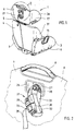
- the child seat 1 shown in FIG. 1 has a seat 2 with two lateral armrests 3 and a backrest 4 with one in the upper Area 5 extendable, d. H. height adjustable, arranged headrest 6. At their Upper area 7 is a bracket 8 for transporting the child seat 1 arranged.
- the child seat 1 is used with its underside 9 on the seat cushion 10 a motor vehicle seat 11 and with its backrest 4 to the vehicle-specific backrest cushion 12, as shown in FIG. 3. As in 7, the child seat 1 is in this position with a three-point belt 13 fixed to the vehicle, the lap belt 14 being provided by recesses 15 on the top side are guided in the armrests 3 of the child seat 1, while the upper area of the shoulder strap 16 by a slit-like Recess 17 is guided on the headrest 6.
- the headrest 6 of the child seat 1 is on the rear 21 an additional fixation strap 22 anchored with which the child seat 1 is additionally attached the vehicle headrest 23 can be fixed.
- the fixation strap 22 is comparatively short, for example only 15 to 30 cm in total long, and it is attached to the child seat 1 approximately in its central region, especially clamped.
- trough-shaped depressions in the rear 21 and in the front 25 of the Child seat headrest 6 provided. This can be achieved, for example, by the fact that which are otherwise separated by a cavity 26 front and Rear wall 25, 21 of a headrest 6 molded as a blow molded part made of plastic trough-shaped are approximated to each other, so that they with their inner Lay surfaces directly next to each other.
- one part 29, 30 is one Belt buckle 31 arranged with which the two ends of the fixing belt 22nd can be fixed to each other.
- One or both parts 29, 30 of the Belt buckle 31 can opposite the relevant end of the fixation belt 22 slidable and lockable to the length of the closed To be able to adapt the belt loop 32 to the respective circumstances.
- a Push button 33 can simply snap into place when plugged together Locking parts 29, 30 can be released from each other again.
- This mechanism can similar or identical to the lock of a three-point, pool or Braces are designed.
- FIG. 1 Another component of the security system according to the invention Side collisions are side supports 36, 37 for the head 19 and torso 38, respectively of the child 20, for this purpose on the side of the headrest 6 or Connect the backrest 4 of the child seat 1.
- the side head and torso supports 36, 37 diverge Viewed from each other slightly, for example with an opening angle of 10 ° to 30 °.
- the side torso supports can be used to improve arm freedom be realized with an even larger opening angle.
- the extension of this Lateral supports in the seating direction can fluctuate between 10 and 20 cm.
- the Base of such a side support 36, 37 can be about a half or Quarter circle correspond, but other designs are also conceivable.
- Integrated side supports 36 can be seen in Figures 4 and 6.
- the wider Middle bar fulfills the usual function of a headrest, while the side legs are designed as side supports 36.
- the inner surfaces of the head 19 of the child 20 facing the Side supports 36 with a soft, damping covering 39 for example in the form of a Foam layer, be provided.
- the wall thickness of the blow molded part which forms the central web 40 of the headrest 6 and the adjoining side supports 36, tapers in the region of the transition 41, 42, so that the stiffness of the headrest part 6 is reduced here. In this way, there is an articulated function which allows a pivoting 43 of the relevant side support 36 under load.
- the regions of curvature 41, 42 do not have an even coaxially coaxial axis of curvature, but the radius of curvature of the outer region of curvature 41 in the exemplary embodiment shown is even outside the convex surface of the inner curvature 42 about the same thickness d as in the area of the side supports 36; however, this thickness increases to almost twice the value in the transition region 41, 42, since the radius of curvature R of the outer transition region 41 is smaller than the sum of the radius of curvature r of the inner transition region 42 plus the average cavity thickness d: R ⁇ r + d.
- the torso side supports 37 are on the backrest 4 according to the same principle limited flexibility and molded on.
- the child seat 1 and the child seat 1 are inside seated child 20 approximately in the middle of the vehicle seat 11 and is in this position both by the vehicle's own three-point belt 13 and in particular by the fixation strap 22 held.
- This strong The child seat 1 takes lateral acceleration without delay because it is tight on the Headrest 23 of the vehicle seat 11 is fixed and therefore hardly has lateral play.
- the child 20 can do this at first sudden lateral movement does not understand and is therefore within his Child seat 1 moved against the direction of impact to the body 18 until it with its torso 38 or its head 19 against the lateral torso support 37 and / or headrest 36 bounces.
- the child seat 1 Since, in contrast to previously known seats, the child seat 1 is still approximately stands in the middle of the vehicle's own seat 11, it always points at this moment still a large distance from the vehicle body or door 18. Thereby and also because of the articulation of the transition areas 41, 42 of the it is the relevant side support 36 relative to the central web 40 of the headrest 6 the side support 36 possible, when the head 19 of the child 20 impacts laterally give way and swing out, as can be seen in Fig. 8.
- the bent-out side support 36 experiences a considerable amount Oblique position in relation to the seat direction, so that the impacting head 19 after is deflected at the front, as the dash-dotted line 45 in Fig. 8 indicates. From the Lateral movement of the head 19 is thereby a forward displacement that the The pretensioner of the three-point belt is registered and thus finally caught. On Most of the force caused by a side-on collision can therefore be used for the Head 19 of the child can be eliminated completely harmlessly via the shoulder strap.
- the lateral torso support 37 can perform a similar function, but with a larger spring constant c can be formed to the greater weight of the upper body of the child 20 with approximately the same degree of deflection can like the side headrests 36.
Landscapes
- Engineering & Computer Science (AREA)
- Health & Medical Sciences (AREA)
- Child & Adolescent Psychology (AREA)
- General Health & Medical Sciences (AREA)
- Aviation & Aerospace Engineering (AREA)
- Transportation (AREA)
- Mechanical Engineering (AREA)
- Seats For Vehicles (AREA)
- Carriages For Children, Sleds, And Other Hand-Operated Vehicles (AREA)
- Passenger Equipment (AREA)
- Mattresses And Other Support Structures For Chairs And Beds (AREA)
Applications Claiming Priority (2)
| Application Number | Priority Date | Filing Date | Title |
|---|---|---|---|
| DE20117074U | 2001-10-22 | ||
| DE20117074U DE20117074U1 (de) | 2001-10-22 | 2001-10-22 | Fahrzeug-Kindersitz |
Publications (3)
| Publication Number | Publication Date |
|---|---|
| EP1304255A2 true EP1304255A2 (fr) | 2003-04-23 |
| EP1304255A3 EP1304255A3 (fr) | 2003-12-17 |
| EP1304255B1 EP1304255B1 (fr) | 2007-05-30 |
Family
ID=7962989
Family Applications (1)
| Application Number | Title | Priority Date | Filing Date |
|---|---|---|---|
| EP02009534A Expired - Lifetime EP1304255B1 (fr) | 2001-10-22 | 2002-04-26 | Siège enfant pour véhicule automobile |
Country Status (5)
| Country | Link |
|---|---|
| EP (1) | EP1304255B1 (fr) |
| AT (1) | ATE363408T1 (fr) |
| DE (2) | DE20117074U1 (fr) |
| DK (1) | DK1304255T3 (fr) |
| ES (1) | ES2288177T3 (fr) |
Cited By (3)
| Publication number | Priority date | Publication date | Assignee | Title |
|---|---|---|---|---|
| NL1023806C2 (nl) * | 2003-07-03 | 2005-01-04 | All Our Kids Europ B V | Ondersteuningsinrichting voor een kind. |
| DE102009034514A1 (de) | 2009-07-24 | 2011-02-03 | Lippmann German Ropes Gmbh & Co. Kg | Seil und Verfahren zum Herstellen des Seiles |
| US9211820B2 (en) * | 2012-11-01 | 2015-12-15 | Graco Children's Products Inc. | Child safety seat with side impact energy redirection |
Families Citing this family (3)
| Publication number | Priority date | Publication date | Assignee | Title |
|---|---|---|---|---|
| DE10213655C1 (de) | 2002-03-27 | 2003-07-24 | Faurecia Autositze Gmbh & Co | Befestigungsvorrichtung für einen Kindersitz auf einem Kraftfahrzeugsitz |
| DE102004015647B4 (de) * | 2004-03-31 | 2015-09-10 | Volkswagen Ag | Befestigungsvorrichtung für einen Kindersitz in einem Kraftfahrzeug |
| DE102005013587B4 (de) * | 2005-03-24 | 2015-04-16 | Bayerische Motoren Werke Aktiengesellschaft | Cabriolet mit einer Befestigungseinrichtung für Kindersitze |
Family Cites Families (10)
| Publication number | Priority date | Publication date | Assignee | Title |
|---|---|---|---|---|
| DE3704972A1 (de) | 1986-12-18 | 1988-09-22 | Hubert Spieleder | Sicherheitskindersitz fuer autos |
| DE3906844A1 (de) * | 1989-03-03 | 1990-09-13 | Hubert Spieleder | Halterung fuer einen autokindersitz |
| DE4230879C2 (de) | 1991-09-30 | 2000-10-19 | Volkswagen Ag | Kindersitzanordnung mit einem auf einen Fahrzeugsitz aufsetzbaren Kindersitz |
| FR2710013B1 (fr) * | 1993-09-16 | 1995-12-08 | Peugeot | Dispositif de maintien latéral pour un siège de véhicule automobile et siège de véhicule pour enfant. |
| DE19612232B4 (de) | 1996-03-27 | 2006-07-13 | Bayerische Motoren Werke Ag | Traggestell zur Abstützung von Gegenständen an einem Fahrzeugsitz eines Kraftfahrzeugs |
| DE19751897B4 (de) | 1996-11-29 | 2005-09-22 | Volkswagen Ag | Rückenstützelement |
| DE19732385C2 (de) | 1997-07-25 | 2000-03-09 | Opel Adam Ag | Befestigung für einen Kindersitz auf dem Rücksitz eines Kraftfahrzeuges |
| JP2000142194A (ja) * | 1998-01-27 | 2000-05-23 | Aprica Kassai Inc | 育児器具 |
| CA2270846C (fr) * | 1998-05-18 | 2007-09-11 | Britax Child Safety Inc. | Siege pour enfant |
| DE29820475U1 (de) | 1998-11-16 | 1999-01-14 | Scheffler, Dieter, 79539 Lörrach | Kindersitz |
-
2001
- 2001-10-22 DE DE20117074U patent/DE20117074U1/de not_active Expired - Lifetime
-
2002
- 2002-04-26 DK DK02009534T patent/DK1304255T3/da active
- 2002-04-26 ES ES02009534T patent/ES2288177T3/es not_active Expired - Lifetime
- 2002-04-26 AT AT02009534T patent/ATE363408T1/de not_active IP Right Cessation
- 2002-04-26 EP EP02009534A patent/EP1304255B1/fr not_active Expired - Lifetime
- 2002-04-26 DE DE50210227T patent/DE50210227D1/de not_active Expired - Fee Related
Non-Patent Citations (1)
| Title |
|---|
| None |
Cited By (3)
| Publication number | Priority date | Publication date | Assignee | Title |
|---|---|---|---|---|
| NL1023806C2 (nl) * | 2003-07-03 | 2005-01-04 | All Our Kids Europ B V | Ondersteuningsinrichting voor een kind. |
| DE102009034514A1 (de) | 2009-07-24 | 2011-02-03 | Lippmann German Ropes Gmbh & Co. Kg | Seil und Verfahren zum Herstellen des Seiles |
| US9211820B2 (en) * | 2012-11-01 | 2015-12-15 | Graco Children's Products Inc. | Child safety seat with side impact energy redirection |
Also Published As
| Publication number | Publication date |
|---|---|
| EP1304255B1 (fr) | 2007-05-30 |
| DE50210227D1 (de) | 2007-07-12 |
| ATE363408T1 (de) | 2007-06-15 |
| ES2288177T3 (es) | 2008-01-01 |
| DK1304255T3 (da) | 2007-10-01 |
| DE20117074U1 (de) | 2002-01-17 |
| EP1304255A3 (fr) | 2003-12-17 |
Similar Documents
| Publication | Publication Date | Title |
|---|---|---|
| DE69923308T2 (de) | Stuhlstruktur | |
| EP1427603B1 (fr) | Dossier de siege de vehicule | |
| EP1594717B1 (fr) | Siege de vehicule reglable en hauteur comportant une unite de blocage pour collisions | |
| EP2456651B1 (fr) | Dispositif de fixation d'une table à la paroi latérale d'un véhicule | |
| DE19859197A1 (de) | Gestell eines Sitzes für ein Automobil mit einer Antidurchtauchquerstrebe | |
| DE1904687A1 (de) | Fahrzeugsitz | |
| EP2022663B1 (fr) | Siège pour enfants à installer dans un véhicule dans le sens opposé à la direction de marche | |
| DE102005043333B4 (de) | Kraftfahrzeugsitz mit einem in der Höhe verstellbaren Sitzkissen und einem mit dem Sitzkissen verbundenen Befestigungspunkt für einen Sicherheitsgurt | |
| WO2018202802A1 (fr) | Siège de véhicule | |
| WO1992005978A1 (fr) | Dispositif de securite anti-choc pour siege de vehicule, notamment pour siege de vehicule automobile | |
| EP2161159B1 (fr) | Dispositif de sécurité pour un siège enfant dans un véhicule | |
| DE3873468T2 (de) | Sicherheitsgurthaltevorrichtung mit manueller lageverstellung. | |
| EP1304255A2 (fr) | Siège enfant pour véhicule automobile | |
| DE3920145A1 (de) | Vorrichtung und verfahren zum schutz einer person, insbesondere eines kleinkindes, in einem kraftfahrzeug | |
| DE102007032524A1 (de) | Fahrzeugsitz mit einer neigungsverstellbaren Rückenlehne, insbesondere für Personenkraftwagen | |
| DE3616452A1 (de) | Einrichtung zum verstellen eines langgestreckten gliedes | |
| EP0963872A2 (fr) | Siège de véhicule à déplacement arrière limité des éléments de siège par absorption d'énergie en cas de choc arrière | |
| EP1344678B1 (fr) | Siège de sécurité pour enfants à installer et fixer sur un siège de véhicule | |
| DE10052838B4 (de) | Armlehne, insbesondere Mittelarmlehne eines Kfz | |
| DE102015204516A1 (de) | Sitzstruktur für einen Fahrzeugsitz | |
| DE10159847A1 (de) | Aktive Rückenlehne für Kraftfahrzeugsitze als Unfallsicherheitsvorrichtung | |
| DE10052829A1 (de) | Vorrichtung zur Arretierung eines beweglichen Körpers, insbesondere in einem Kfz | |
| DE102005053741B3 (de) | Fahrzeug-Sitzeinrichtung mit einem aktiven Kopfstützen-System | |
| EP2146868A1 (fr) | Appuie-tête actif pour banquette arrière d'automobile | |
| EP2177395B1 (fr) | Moyen d'absorption des forces de collision survenant sur une ceinture de sécurité sur un siège de sécurité pour enfant |
Legal Events
| Date | Code | Title | Description |
|---|---|---|---|
| PUAI | Public reference made under article 153(3) epc to a published international application that has entered the european phase |
Free format text: ORIGINAL CODE: 0009012 |
|
| AK | Designated contracting states |
Designated state(s): AT BE CH CY DE DK ES FI FR GB GR IE IT LI LU MC NL PT SE TR |
|
| AX | Request for extension of the european patent |
Extension state: AL LT LV MK RO SI |
|
| PUAL | Search report despatched |
Free format text: ORIGINAL CODE: 0009013 |
|
| AK | Designated contracting states |
Kind code of ref document: A3 Designated state(s): AT BE CH CY DE DK ES FI FR GB GR IE IT LI LU MC NL PT SE TR |
|
| AX | Request for extension of the european patent |
Extension state: AL LT LV MK RO SI |
|
| 17P | Request for examination filed |
Effective date: 20040526 |
|
| AKX | Designation fees paid |
Designated state(s): AT BE CH CY DE DK ES FI FR GB GR IE IT LI LU MC NL PT SE TR |
|
| RAP1 | Party data changed (applicant data changed or rights of an application transferred) |
Owner name: RECARO GMBH & CO. KG |
|
| GRAP | Despatch of communication of intention to grant a patent |
Free format text: ORIGINAL CODE: EPIDOSNIGR1 |
|
| GRAS | Grant fee paid |
Free format text: ORIGINAL CODE: EPIDOSNIGR3 |
|
| GRAA | (expected) grant |
Free format text: ORIGINAL CODE: 0009210 |
|
| AK | Designated contracting states |
Kind code of ref document: B1 Designated state(s): AT BE CH CY DE DK ES FI FR GB GR IE IT LI LU MC NL PT SE TR |
|
| PG25 | Lapsed in a contracting state [announced via postgrant information from national office to epo] |
Ref country code: FI Free format text: LAPSE BECAUSE OF FAILURE TO SUBMIT A TRANSLATION OF THE DESCRIPTION OR TO PAY THE FEE WITHIN THE PRESCRIBED TIME-LIMIT Effective date: 20070530 |
|
| REG | Reference to a national code |
Ref country code: GB Ref legal event code: FG4D Free format text: NOT ENGLISH |
|
| REG | Reference to a national code |
Ref country code: CH Ref legal event code: EP |
|
| REG | Reference to a national code |
Ref country code: IE Ref legal event code: FG4D Free format text: LANGUAGE OF EP DOCUMENT: GERMAN |
|
| REF | Corresponds to: |
Ref document number: 50210227 Country of ref document: DE Date of ref document: 20070712 Kind code of ref document: P |
|
| PG25 | Lapsed in a contracting state [announced via postgrant information from national office to epo] |
Ref country code: SE Free format text: LAPSE BECAUSE OF FAILURE TO SUBMIT A TRANSLATION OF THE DESCRIPTION OR TO PAY THE FEE WITHIN THE PRESCRIBED TIME-LIMIT Effective date: 20070830 |
|
| GBT | Gb: translation of ep patent filed (gb section 77(6)(a)/1977) |
Effective date: 20070828 |
|
| REG | Reference to a national code |
Ref country code: DK Ref legal event code: T3 |
|
| ET | Fr: translation filed | ||
| NLV1 | Nl: lapsed or annulled due to failure to fulfill the requirements of art. 29p and 29m of the patents act | ||
| REG | Reference to a national code |
Ref country code: ES Ref legal event code: FG2A Ref document number: 2288177 Country of ref document: ES Kind code of ref document: T3 |
|
| REG | Reference to a national code |
Ref country code: IE Ref legal event code: FD4D |
|
| PG25 | Lapsed in a contracting state [announced via postgrant information from national office to epo] |
Ref country code: NL Free format text: LAPSE BECAUSE OF FAILURE TO SUBMIT A TRANSLATION OF THE DESCRIPTION OR TO PAY THE FEE WITHIN THE PRESCRIBED TIME-LIMIT Effective date: 20070530 Ref country code: PT Free format text: LAPSE BECAUSE OF FAILURE TO SUBMIT A TRANSLATION OF THE DESCRIPTION OR TO PAY THE FEE WITHIN THE PRESCRIBED TIME-LIMIT Effective date: 20071030 Ref country code: IE Free format text: LAPSE BECAUSE OF FAILURE TO SUBMIT A TRANSLATION OF THE DESCRIPTION OR TO PAY THE FEE WITHIN THE PRESCRIBED TIME-LIMIT Effective date: 20070530 |
|
| PLBE | No opposition filed within time limit |
Free format text: ORIGINAL CODE: 0009261 |
|
| STAA | Information on the status of an ep patent application or granted ep patent |
Free format text: STATUS: NO OPPOSITION FILED WITHIN TIME LIMIT |
|
| PG25 | Lapsed in a contracting state [announced via postgrant information from national office to epo] |
Ref country code: IT Free format text: LAPSE BECAUSE OF FAILURE TO SUBMIT A TRANSLATION OF THE DESCRIPTION OR TO PAY THE FEE WITHIN THE PRESCRIBED TIME-LIMIT Effective date: 20070530 Ref country code: GR Free format text: LAPSE BECAUSE OF FAILURE TO SUBMIT A TRANSLATION OF THE DESCRIPTION OR TO PAY THE FEE WITHIN THE PRESCRIBED TIME-LIMIT Effective date: 20070831 |
|
| 26N | No opposition filed |
Effective date: 20080303 |
|
| BERE | Be: lapsed |
Owner name: RECARO G.M.B.H. & CO. KG Effective date: 20080430 |
|
| PG25 | Lapsed in a contracting state [announced via postgrant information from national office to epo] |
Ref country code: MC Free format text: LAPSE BECAUSE OF NON-PAYMENT OF DUE FEES Effective date: 20080430 |
|
| REG | Reference to a national code |
Ref country code: CH Ref legal event code: PL |
|
| PG25 | Lapsed in a contracting state [announced via postgrant information from national office to epo] |
Ref country code: LI Free format text: LAPSE BECAUSE OF NON-PAYMENT OF DUE FEES Effective date: 20080430 Ref country code: CH Free format text: LAPSE BECAUSE OF NON-PAYMENT OF DUE FEES Effective date: 20080430 |
|
| PG25 | Lapsed in a contracting state [announced via postgrant information from national office to epo] |
Ref country code: BE Free format text: LAPSE BECAUSE OF NON-PAYMENT OF DUE FEES Effective date: 20080430 |
|
| PGFP | Annual fee paid to national office [announced via postgrant information from national office to epo] |
Ref country code: DK Payment date: 20090313 Year of fee payment: 8 |
|
| PGFP | Annual fee paid to national office [announced via postgrant information from national office to epo] |
Ref country code: GB Payment date: 20090312 Year of fee payment: 8 |
|
| PG25 | Lapsed in a contracting state [announced via postgrant information from national office to epo] |
Ref country code: CY Free format text: LAPSE BECAUSE OF FAILURE TO SUBMIT A TRANSLATION OF THE DESCRIPTION OR TO PAY THE FEE WITHIN THE PRESCRIBED TIME-LIMIT Effective date: 20070530 |
|
| PGFP | Annual fee paid to national office [announced via postgrant information from national office to epo] |
Ref country code: ES Payment date: 20090414 Year of fee payment: 8 |
|
| PGFP | Annual fee paid to national office [announced via postgrant information from national office to epo] |
Ref country code: AT Payment date: 20090312 Year of fee payment: 8 Ref country code: DE Payment date: 20090430 Year of fee payment: 8 Ref country code: FR Payment date: 20090406 Year of fee payment: 8 |
|
| PG25 | Lapsed in a contracting state [announced via postgrant information from national office to epo] |
Ref country code: LU Free format text: LAPSE BECAUSE OF NON-PAYMENT OF DUE FEES Effective date: 20080426 |
|
| PG25 | Lapsed in a contracting state [announced via postgrant information from national office to epo] |
Ref country code: TR Free format text: LAPSE BECAUSE OF FAILURE TO SUBMIT A TRANSLATION OF THE DESCRIPTION OR TO PAY THE FEE WITHIN THE PRESCRIBED TIME-LIMIT Effective date: 20070530 |
|
| REG | Reference to a national code |
Ref country code: DK Ref legal event code: EBP |
|
| GBPC | Gb: european patent ceased through non-payment of renewal fee |
Effective date: 20100426 |
|
| REG | Reference to a national code |
Ref country code: FR Ref legal event code: ST Effective date: 20101230 |
|
| PG25 | Lapsed in a contracting state [announced via postgrant information from national office to epo] |
Ref country code: AT Free format text: LAPSE BECAUSE OF NON-PAYMENT OF DUE FEES Effective date: 20100426 |
|
| PG25 | Lapsed in a contracting state [announced via postgrant information from national office to epo] |
Ref country code: DE Free format text: LAPSE BECAUSE OF NON-PAYMENT OF DUE FEES Effective date: 20101103 |
|
| PG25 | Lapsed in a contracting state [announced via postgrant information from national office to epo] |
Ref country code: GB Free format text: LAPSE BECAUSE OF NON-PAYMENT OF DUE FEES Effective date: 20100426 |
|
| PG25 | Lapsed in a contracting state [announced via postgrant information from national office to epo] |
Ref country code: DK Free format text: LAPSE BECAUSE OF NON-PAYMENT OF DUE FEES Effective date: 20100503 |
|
| REG | Reference to a national code |
Ref country code: ES Ref legal event code: FD2A Effective date: 20110714 |
|
| PG25 | Lapsed in a contracting state [announced via postgrant information from national office to epo] |
Ref country code: ES Free format text: LAPSE BECAUSE OF NON-PAYMENT OF DUE FEES Effective date: 20110704 |
|
| PG25 | Lapsed in a contracting state [announced via postgrant information from national office to epo] |
Ref country code: ES Free format text: LAPSE BECAUSE OF NON-PAYMENT OF DUE FEES Effective date: 20100427 |
|
| PG25 | Lapsed in a contracting state [announced via postgrant information from national office to epo] |
Ref country code: FR Free format text: LAPSE BECAUSE OF NON-PAYMENT OF DUE FEES Effective date: 20100430 |