EP1303937B1 - Bestimmung der verbindungsqualität eines übertragungskanals in einem ofdm-übertragungssystem - Google Patents
Bestimmung der verbindungsqualität eines übertragungskanals in einem ofdm-übertragungssystem Download PDFInfo
- Publication number
- EP1303937B1 EP1303937B1 EP01960558A EP01960558A EP1303937B1 EP 1303937 B1 EP1303937 B1 EP 1303937B1 EP 01960558 A EP01960558 A EP 01960558A EP 01960558 A EP01960558 A EP 01960558A EP 1303937 B1 EP1303937 B1 EP 1303937B1
- Authority
- EP
- European Patent Office
- Prior art keywords
- link quality
- noise
- det
- signal
- sub
- Prior art date
- Legal status (The legal status is an assumption and is not a legal conclusion. Google has not performed a legal analysis and makes no representation as to the accuracy of the status listed.)
- Expired - Lifetime
Links
Images


Classifications
-
- H—ELECTRICITY
- H04—ELECTRIC COMMUNICATION TECHNIQUE
- H04L—TRANSMISSION OF DIGITAL INFORMATION, e.g. TELEGRAPHIC COMMUNICATION
- H04L27/00—Modulated-carrier systems
- H04L27/26—Systems using multi-frequency codes
- H04L27/2601—Multicarrier modulation systems
- H04L27/2647—Arrangements specific to the receiver only
-
- H—ELECTRICITY
- H04—ELECTRIC COMMUNICATION TECHNIQUE
- H04L—TRANSMISSION OF DIGITAL INFORMATION, e.g. TELEGRAPHIC COMMUNICATION
- H04L1/00—Arrangements for detecting or preventing errors in the information received
- H04L1/20—Arrangements for detecting or preventing errors in the information received using signal quality detector
- H04L1/208—Arrangements for detecting or preventing errors in the information received using signal quality detector involving signal re-encoding
-
- H—ELECTRICITY
- H04—ELECTRIC COMMUNICATION TECHNIQUE
- H04L—TRANSMISSION OF DIGITAL INFORMATION, e.g. TELEGRAPHIC COMMUNICATION
- H04L25/00—Baseband systems
- H04L25/02—Details ; arrangements for supplying electrical power along data transmission lines
- H04L25/0202—Channel estimation
- H04L25/0204—Channel estimation of multiple channels
-
- H—ELECTRICITY
- H04—ELECTRIC COMMUNICATION TECHNIQUE
- H04L—TRANSMISSION OF DIGITAL INFORMATION, e.g. TELEGRAPHIC COMMUNICATION
- H04L1/00—Arrangements for detecting or preventing errors in the information received
- H04L1/0001—Systems modifying transmission characteristics according to link quality, e.g. power backoff
- H04L1/0002—Systems modifying transmission characteristics according to link quality, e.g. power backoff by adapting the transmission rate
- H04L1/0003—Systems modifying transmission characteristics according to link quality, e.g. power backoff by adapting the transmission rate by switching between different modulation schemes
-
- H—ELECTRICITY
- H04—ELECTRIC COMMUNICATION TECHNIQUE
- H04L—TRANSMISSION OF DIGITAL INFORMATION, e.g. TELEGRAPHIC COMMUNICATION
- H04L1/00—Arrangements for detecting or preventing errors in the information received
- H04L1/0001—Systems modifying transmission characteristics according to link quality, e.g. power backoff
- H04L1/0009—Systems modifying transmission characteristics according to link quality, e.g. power backoff by adapting the channel coding
Definitions
- the present invention relates to a link quality determination unit and a link quality determination method for determining a link quality of a transmission link between an OFDM transmitter and an OFDM receiver of an OFDM transmission system.
- the present invention also relates to a transmission link property selector including such a link quality determination unit.
- a transmission link quality measure is to be determined in order to allow the selecting and adjusting of transmission properties or transmission characteristics of the transmissions on the transmission link.
- the OFDM transmission signal can be evaluated to obtain parameters based on which a suitable link quality measure is determined.
- the present invention in particular addresses the problem how such a link quality measure can be obtained with high accuracy in an OFDM (Orthogonal Frequency Division Multiplexing) system.
- the present invention also relates to processing devices which can provide the necessary parameters from which the quality measure can be constructed.
- Orthogonal Frequency Division Multiplexing is a modulation scheme which is typically used in transmission systems exhibiting a time dispersion which is much greater than the bit period.
- OFDM is already specified in Digital Audio Broadcasting (DAB) and Digital Video Broadcasting (DVB).
- DAB Digital Audio Broadcasting
- DVD Digital Video Broadcasting
- OFDM is also contemplated for use in Wireless Local Area Networks (WLAN) in the 5 GHz band as specified in Europe, USA and Japan.
- the European standard is the so-called HIgh PErformance Radio Local Area Network type 2 (HIPERLAN/2). This standard is currently being developed by the ETSI (European Telecommunication Standard Institute) Project BRAN (Broadband Radio Access Network).
- ETSI European Telecommunication Standard Institute
- Project BRAN Broadband Radio Access Network
- an OFDM transmission TR and an OFDM receiver RC communicate over a transmission link TL.
- the transmitter TR comprises conventional modulation circuitry MODCRT for modulating some source information into a plurality of OFDM symbols on a plurality of subcarriers. As is known to the skilled person, this is performed by using essentially a coder and an inverse discrete Fourier transform process.
- the receiver RC comprises some conventional demodulation circuitry DEMCRT for demodulating the OFDM symbols on the plurality of subcarriers back into the source information.
- demodulated circuitry DEMCRT comprises as main components a decoder and a discrete Fourier transform.
- the transmission system SYS may be a fixed network or a mobile radio communication network where for example access points AP are used in order to provide an access to a receiver RC, e.g. a mobile terminal MT.
- a receiver RC e.g. a mobile terminal MT.
- the system architecture also applies to other types of transmission systems in addition to a mobile radio communication network.
- Fig. 1a shows an example of the data transmission in accordance with the HIPERLAN/2 standard according to which a transmission in terms of MAC (Multiple Access Control) frames FR having a duration of e.g. 2 ms takes place.
- each transmission frame FR consists of Broadcast Control Channel BCCH information followed by Frame Control Channel FCC information after which the respective downlink traffic and uplink traffic and information of Random Access Channels RAC follows.
- the actual OFDM symbols are contained in individual bursts BST.
- Each burst BST contains a preamble part PRE and some protocol data units PDU.
- the preamble part PRE is necessary in each burst in order to allow error correction and receiver training.
- each preamble part PRE comprises two training symbols TS and a cyclic prefix CP.
- a cyclic prefix CP There are several different preambles for the different burst types for downlink, uplink and random access. However, every preamble includes the same part of the cyclic prefix CP and training symbols TS to allow a channel estimation.
- each preamble PRE contains 32 samples for the cyclic prefix CP and 64 samples for each training symbol.
- the transmission via the transmission link TL suffers from noise, distortion or other interferences such that the receiver RC can make wrong decisions regarding the assumed sent OFDM information.
- One of the reasons to include the known training symbols (i.e. also known on the receiver side) into the respective preamble part is to allow a receiver training, i.e. to compare the received training symbols with the known training symbols for example to estimate the channel coefficients in the receiver RC in order to avoid wrong decisions as much as possible.
- the transmitter TR is typically equipped with a transmission link property adjustment unit ADP which can dynamically adapt or adjust the transmission characteristics of the communication on a transmission link TL.
- the adjustment unit ADP performs a function which is usually referred to as link adaptation (LA), i.e. a setting of predetermined transmission properties which are assumed to increase the transmission link quality.
- LA link adaptation
- various physical layer modes can be set by the adjustment unit ADP.
- Fig. 2a shows the key parameters of the HIPERLAN/2 physical layer modes.
- LA should be understood as a general term for methods to select transmitter parameters. This, for instance, includes the setting of output power, which is also referred to as power control. For example, in a conventional transmitter the transmission power may be controlled on the basis of the received power at the receiver and/or on the basis of the measured SNR.
- HIPERLAN/2 provides six mandatory modes with bit rates of 6, 9, 12, 18, 27, 36 Mbps and one further optional mode with a bit rate of 54 Mbps.
- bit rates 6-9, 18, 27, 36 Mbps
- bit rate 54 Mbps.
- the adjustment unit ADP needs an indication from a transmission link property selector TL-SEL in order to know which physical layer mode needs to be selected.
- the transmission link property selector TL-SEL is formed by a link quality measurement unit LQ-DET which performs link quality measurements (LQMs) on the transmission link TL and which outputs a link quality measure Q to a transmission property decider TR-DEC.
- LQ-DET link quality measurement unit
- the transmission property decider TR-DEC decides the physical layer mode and provides an indication with respect to the selected physical layer mode to the adjustment unit ADP which then sets the selected physical layer mode.
- Link quality measurements can in principle be carried out by a link quality measurement unit LQ-DET on the transmitter TR or elsewhere in the access point AP site (the transmitter is part of the access point AP), on the receiver RC site or even within another unit AU of the transmission system SYS involved in the communication and being arranged elsewhere, i.e. neither in the access point AP or the transmitter TR or the receiver RC.
- the transmission property decider TR-DEC may be provided in the transmitter TR or elsewhere in the access point AP, in the receiver RC or in any other unit AU. If the transmission property decider and the link quality measurement unit are provided outside the transmitter TR, the adjustment unit ADP will eventually receive a corresponding signal from the outside provided transmission property decider TR-DEC.
- the transmission link property selector TL-SEL constituted by the transmission property decider TR-DEC and the link quality measurement unit LQ-DET should not be seen as situated exclusively in the transmitter TR or receiver RC since the particular arrangement will depend on the system implementation.
- a common aspect is that LQMs must be carried out and a corresponding selection signal with respect to the selected physical layer mode must be provided to the adjustment unit ADP.
- Link adaptation (LA) schemes may use a variety of link quality measurements which may be derived either on the data link control (DLC) layer or the physical layer.
- the link quality measure is the very criterion which will be used as decision criterion for selecting the appropriate transmission mode. For example, if the link quality measure is not accurate, an over compensation, i.e. a lower bit rate than would actually be possible, may be selected. Likewise, if the link quality measure is incorrect, i.e. predicts a better transmission quality than it is actually present, then a too high bit rate may be selected than would actually be appropriate. Therefore, the determination of the link quality measure, i.e. how the link quality measurements are carried out and what parameters are used for deriving the link quality measure, is of essential importance for an accurate link adaptation.
- EP 0 899 906 A2 describes a system and method for measuring channel quality information in terms of signal-to-noise ratio for the transmission of coded signals over fading channels.
- a Viterbi decoder metric for the maximum likelihood path is used which is an Euclidean distance metric. This metric is filtered and averaged to give a reliable channel quality measure which remains consistent across different coded modulation schemes and at different mobile speeds.
- FR 2 742 613 teaches an evaluation method for a quality factor which is representative of a transmission channel of a digital signal.
- the quality factor is in principle based on summed-up differences between corrected signal vectors and estimated signal vectors, wherein the summing-up comprises several sequentially transmitted vectors.
- a link quality measure available on the data link layer is based on PDU (Protocol Data Unit) Error Rate (PER) estimates (or Frame Error Rate Estimates) derived from CRC (Cyclic Redundancy Check).
- PDU Protocol Data Unit
- PER Error Rate
- CRC Cyclic Redundancy Check
- RSS Received Signal Strength
- SNR Signal-to-Noise power Ratio
- a quality measure or a quality criterion is derived which is then used for the link adaptation as explained above. If for example in HIPERLAN/2 a packet data transmission without a delay constraint is assumed, a suitable quality measure is the maximum link throughput of data in terms of Mbps.
- the link throughput of an ideal selective-repeat ARQ (Automatic Repeat reQuest) scheme can be simply approximated by (bit rate)*(1-PER). Obviously, the PER would be the measure of interest.
- a reliable direct measurement of PER takes too much time and therefore an indirect estimation of the PER, for example via a SNR estimate, is a straightforward measurement.
- PER as a function of the SNR depends on further channel parameters. For instance, the error rate as a function of SNR or carrier-to-interference power ratio may be significantly different for different channel characteristics like delay spread. Therefore, further measurements need to be taken into account.
- link quality measurements LQM have already been considered for other systems like GPRS (General Packet Radio System) and EDGE (Enhanced Data Rates for Global Evolution).
- the link quality measures in such systems are essentially based on bit error rate measurements, signal-to-noise estimates or estimates of the received signal strength.
- link quality measures can not easily be used in OFDM systems like HIPERLAN/2.
- channel parameters like the delay spread affect the link quality and hence, the desired link adaptation behaviour and the switching criteria. Such effects are not taken into account by the conventional link quality measures.
- link quality measures such as the SNR, PER and RSS
- link quality measures do not take into account the characteristics of the instantaneous channel realization. In particular, they do not take into account the characteristics like the delay spread, and consequently the use of such link quality measures in an OFDM system does not lead to an accurate link adaptation.
- the object of the present invention is to provide a link quality determination unit, a link quality determination method and a transmission link property selector including such a link quality determination unit which allow to provide an accurate link quality measure of a transmission link in a OFDM transmission system.
- the present invention also aims at providing processing devices which can provide suitable parameters necessary for deriving the improved link quality measure.
- a link quality determination unit for determining a link quality of a transmission link between an OFDM transmitter and an OFDM receiver of an OFDM transmission system, wherein said link quality determination unit comprises a signal power variation determining unit adapted to determine the signal power variation of the reception signal in the receiver and at least a first link quality measure determination unit adapted to determine a first link quality measure representing the variation of the subcarrier signal power on the basis of the signal power variation as determined by the signal power variation determining unit.
- a link quality determination unit for determining a link quality of a transmission link between an OFDM transmitter and an OFDM receiver of an OFDM transmission system
- said link quality determination unit comprises a signal-to-noise variation determining unit adapted to determine the signal-to-noise variation of the reception signal in the receiver and at least a first link quality measure determination unit adapted to determine a first link quality measure representing the variation of the signal-to-noise variation on the basis of the signal-to-noise variation as determined by the signal-to-noise variation determining unit.
- a transmission link property selector (claim 18) including a transmission link property decider for selecting transmission properties of an OFDM transmission link depending on a transmission link quality measure, wherein said transmission link property selector comprises a link quality determining unit as defined above for outputting said link quality measure, and said transmission link property decider is adapted to decide on the transmission properties of said transmission link on the basis of the link quality measure output by the link quality determination unit.
- a link quality determination method for determining a link quality of a transmission link between an OFDM transmitter and an OFDM receiver of an OFDM transmission system including the steps of determining the signal power variation and determining a first link quality measure on the basis of the determined signal power variation.
- a link quality determination method for determining a link quality of a transmission link between an OFDM transmitter and an OFDM receiver of an OFDM transmission system including the steps of determining the signal-to-noise variation and determining a first link quality measure on the basis of the determined signal-to-noise variation.
- variations of some critical values for the transmission are determined, to include effects due to the frequency-selective channel, i.e. to include the effects of the instantaneous channel frequency response which significantly affects the instantaneous error rate, in the derivation of a suitable link quality measure.
- the delay spread as one of the channel parameters can be included in the link quality measure and thus in the link adaptation behaviour and in the switching criteria.
- the link quality determination unit comprises a channel coefficient estimator which is adapted to determine estimates of the channel coefficients for the respective subcarriers.
- the determined variance of the signal power allows in an easy manner to estimate an accurate signal power variation.
- the first link quality measure determination unit is adapted to determine the first link quality measure by determining a ratio of the signal power variation to the squared signal power. This allows in an advantageous manner to normalize the link quality measure in order to eliminate constant factors in the receiver chain.
- a noise sample estimate determination unit can be provided in order to determine a noise sample estimate for each subcarrier in each OFDM symbol, wherein said signal-to-noise variation determining unit is adapted to determine as the signal-to-noise variation the signal-to-noise variance by determining a SNR mean value by respectively summing the power of the channel estimation coefficients and the power of the noise samples over the plurality of subcarriers and by forming the ratio thereof and by determining the ratio of the power of the respective channel coefficient estimate for the respective subcarrier to the power of the respective noise sample estimate for the respective subcarrier, by subtracting from this ratio the SNR mean value, determining the absolute value of the subtraction result, squaring the absolute value and averaging the determined absolute values over a plurality of subcarriers.
- the variance of the signal-to-noise ratio may be used as an accurate reflection of the variation of the signal-to-noise power.
- the link quality determination unit comprises said signal-to-noise variation determining unit is adapted to determine as the signal-to-noise variation the signal-to-noise variance by determining the ratio of the power of the respective channel coefficient estimate for the respective subcarriers to the power of the respective noise sample estimate for the respective subcarrier, and by averaging the determined ratios over a plurality of subcarriers.
- an overall link quality measure determining unit can advantageously determine an overall link quality measure by combining the first and second link quality measures (claim 17).
- the link adaptation (claim 18) can advantageously be based on the first link quality measure, the second link quality measure or a combination of both link quality measures, i.e. an overall link quality measure.
- the link quality determination unit comprises a channel coefficient estimater which is adapted to determine estimates of the channel coefficients for the respective subcarriers; a signal power determining unit which is adapted to determine the signal power by averaging the power of the estimated channel coefficients over a plurality of subcarriers; said noise power determination unit including a noise sample estimate determining unit which is adapted to determine a noise sample estimate for each subcarrier in each OFDM symbol; and a noise sample averaging unit which is adapted to determine the noise power by averaging the noise sample estimate power over a plurality of subcarriers; wherein said second link quality measure determination unit is adapted to determine said second link quality measure by determining the ratio of the determined signal power to said determined noise power.
- said noise sample averaging unit is further adapted to determine the noise power by averaging said noise sample estimate power also over a plurality of OFDM symbols. This allows to provide an even more accurate second link quality measure representing the average subcarrier signal-to-noise power ratio.
- said noise sample estimate determining unit is adapted to determine said noise sample estimates for each subcarrier in each OFDM symbol on the basis of the respective received signal sample on the respective subcarrier in the respective OFDM symbol, of subcarrier symbol information about the subcarrier symbol transmitted on the respective subcarrier in the respective OFDM symbol, and of the channel coefficient estimate on the respective subcarrier.
- This determination of noise sample estimates is particularly advantageous, because it is based on a suitable model of an equivalent communication channel in an OFDM system.
- said noise sample estimate determining unit comprises a multiplier for multiplying the channel coefficient estimate on the respective subcarrier with the subcarrier symbol information and a subtractor for subtracting the multiplication result from the respective received signal sample, the output of the subtractor constituting said noise sample estimates for each subcarrier in each OFDM symbol.
- the subcarrier symbol information used for the determination of the noise sample estimates is the subcarrier symbol information of one or more OFDM training symbols contained in the preamble part of a burst.
- the known training symbols can be used for determining noise sample estimates.
- the subcarrier symbol information can be a subcarrier symbol estimate information of data-bearing subcarrier symbols within the protocol data units within a burst.
- the subcarrier symbol estimate information of data-bearing subcarrier symbols within the protocol data units within a burst is generated by a remodulation unit which is adapted for re-modulation of OFDM symbol decisions output by the demodulator.
- the subcarrier symbol estimate information of data-bearing subcarrier symbols within the protocol data units within a burst is generated by a reencoding/remodulation unit which is adapted for re-encoding/re-modulating of the output by the decoder.
- said second link quality measure determination unit determines the second link quality measure at several instances during a frame or during bursts and calculates a modified first link measure as a cumulative density function. This allows to account for interference power which may be quickly fluctuating from frame to frame or even within the frames, i.e. in transmission conditions with a dominating interference.
- the invention is not restricted to a specific value mentioned below, e.g. the number of subcarriers or the number of pilot subcarriers.
- the invention is not restricted to the use in a HIPERLAN/2 system and may be used in any other OFDM communication system, wireless or wire-based, the common feature being that an OFDM modulation and OFDM demodulation is carried out in a transmitter and receiver, respectively, and that preferably link adaptation is possible on the basis of link quality criteria.
- the present invention is generally applicable to an OFDM communication system SYS shown in Fig. 1 , i.e. including a transmitter TR and a receiver RC which respectively include the link quality measurement determination unit LQ-DET and the transmission property decider TR-DEC.
- OFDM can be viewed as a set of equivalent communication channels on the various subcarriers.
- the equivalent channels are independent if there is no inter-subcarrier interference.
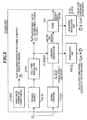
- a model for an equivalent communication channel on one subcarrier is shown in. Fig. 3 .
- the following parameters are defined in Fig. 3 :
- the actual subcarrier symbol transmitted on the subcarrier m in OFDM symbol k by the transmitter TR as well as the channel coefficient on the subcarrier n will not be known.
- estimates of the transmitted subcarrier symbols and estimates of the channel coefficients can be derived. These estimates are denoted as follows:
- the equivalent communication model on subcarriers essentially assumes, for each subcarrier m, that the channel coefficient H m will be multiplied by a multiplier MULT with the transmitted subcarrier symbol A m [k] and that there is an additive noise or interference sample Z m [k] added by the adder ADD.
- the result of the multiplication and addition is the received signal sample on the subcarrier m in the OFDM symbol k.
- the underlying idea of the present invention is that during transmission and reception the OFDM signal is attenuated and distorted by a frequency-selective channel and that the noise and/or interference with an unknown level is added via an addition ADD on each subcarrier. As shown in Fig. 3 , according to the principle of the invention these two effects can be separated. Since the instantaneous channel frequency response significantly affects the instantaneous error rate, in accordance with the invention the signal power variations over a plurality of subcarriers need to be taken into account.
- a link quality determination unit LQ-DET in accordance with the invention for determining a link quality LQ of a transmission link TL between an OFDM transmitter TR and an OFDM receiver RC of an OFDM transmission system SYS comprises a signal power variation determining unit VS-DET which is adapted to determine the signal power variation V S of the OFDM reception signal RS in the receiver RC. Furthermore, there is provided at least a first link quality measure determination unit Q1-OET adapted to determine a first link quality measure Q1 representing the variation of the subcarrier signal power on the basis of the signal power variation V S as determined by the signal power variation determining unit VS-DET.
- the signal power variation characterizes the instantaneous channel impulse response, and, more particular, its impact on the error rate performance. In this respect, it can be viewed as a refinement of the estimate of the error rate that could be obtained by the SNR estimate only.
- the signal power variation is a suitable measure because it is strictly connected to the "instantaneous" delay spread of the instantaneous channel impulse response.
- the signal power variation determined over the subcarriers is a better measure than a characterization of the time-domain impulse response, because coding is effectively performed on the subcarrier symbols in the frequency domain.
- the total signal power is formed by contributions of the power of each individual subcarrier.
- the determination of a signal power variation in accordance with the invention means firstly the determination of a deviation of each subcarrier's power contribution with respect to a predetermined power comparison level and the combining of all the subcarrier power deviations into a common signal power variation value.
- a time-dependent signal power variation determination is considered by the invention.
- the individual subcarrier powers are first integrated (average) a plurality of times and only the thus averaged individual subcarrier powers are compared with the power threshold and only then the thus determined power deviation values are combined into the overall signal power variation value.
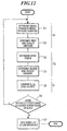
- Fig. 13a shows a flow diagram of step S1 shown in Fig. 12.
- Fig. 12 shows an overall flowchart of the invention for determining at least two different link quality measurement criteria.
- a power comparison value must be determined with respect to which the deviation of the respective subcarrier power is evaluated.
- V S the average signal power can be estimated as the power comparison level.
- a channel coefficient estimator HM-EST (see also Fig. 8 ) is conventionally used and is adapted to determine estimates ⁇ m of the channel coefficients for the respective m subcarriers. Therefore, in step S11 an estimation of the channel coefficients ⁇ m is calculated. That is, the channel coefficient estimates are available from a channel estimation which is applied conventionally for the coherent demodulation.
- step S12 the signal power determining unit PS-DET determines the signal power P S by averaging the power of the estimated channel coefficients ⁇ m over a plurality N ST of the subcarriers. It is worth noting that all averaging processes mentioned here may be calculated from e.g. 52 used subcarriers. Alternatively, they may be calculated based on 48 data carriers without loosing significant accuracy. This may for example be suitable if the pilot subcarriers are not evaluated for any other purpose and only the data-bearing subcarriers are evaluated.
- the signal power variation determination unit in Fig. 4b also receives as input the channel estimates ⁇ m and the determined signal power P S . Then, the signal power variation determination unit VS-DET determines as the signal power variation V S the signal power variance by determining the difference between the power of the estimated channel coefficients ⁇ m on the respective m subcarrier and the signal power P S , determining the absolute value of the difference, squaring the absolute value of the difference and averaging the squared absolute value over a plurality N ST of the subcarriers.
- this calculation is equivalent to determining the fourth power of the channel estimates ⁇ m , subtracting the squared value of the signal power P S 2 and averaging the result over the N ST subcarriers.
- the first link quality measure determination unit Q1-OET determines the first link quality measure Q 1 on the basis of the determined signal power variation V S .
- the first link quality measure determination unit Q1-DET simply outputs the signal power variation as the quality criterion to be used by the selector and the adjustment unit for readjusting the physical layer mode.
- the first link quality measure determination unit Q1-OET is also adapted to determine said first link quality measure Q 1 by determining a ratio of the signal power variation V S to the signal power P S in accordance with the following equation:
- P S - 1 2 1 N ST ⁇ m ⁇ ⁇ ST H ⁇ m 4
- the first link quality measure determination unit Q1-DET normalizes the variance V S of the signal power in order to eliminate constant factors in the receiver chain.
- the squared means signal power is used for this purpose.
- equation (3) gives one example how the first link quality measure Q 1 can be calculated
- other efficient implementations of the first link quality measure can be devised on the basis of the determined signal power variation V S , i.e. slightly different formulas may be used to obtain other first link quality measures Q 1 .
- it may be more suitable to use a value of Q1 10 log 10 (Q 1 /N ST ) instead of Q 1 to reduce the number of divisions. Therefore, the aforementioned equation (3) is only one example how the first link quality measure determination unit Q1-DET may be used in order to determine a first link quality measure Q 1 on the basis of the determined signal power variation or signal power variance V S .
- V S of the signal power does not take into account the dependencies between neighbouring signals. That is, in accordance with the communication model in Fig. 3 , the individual subcarriers are independent. This is a reasonable assumption because a typical OFDM receiver RC uses a de-interleaver to ideally remove respective correlations before decoding. Thus, the subcarrier power or the estimated channel coefficients may be regarded as independent from each other.
- the idea of the invention is to provide a link quality measure by accounting for the delay spread by evaluating the variation of the signal power variations in all subcarriers.
- Fig. 5a there are other suitable parameters whose variation can be evaluated in order to account for the frequency selectivity of the instantaneous channel frequency response.
- a link quality determination unit LQ-DET comprises a signal-to-noise variation determination unit SNRV-DET adapted to determine the signal-to-noise variation SNRV of the reception signal RS in the receiver RC. Furthermore, as in Fig. 4a , a link quality measure determination unit Q1-DET is provided to determine a first link quality measure Q 1 representing the variation of the signal-to-noise ratio on the basis of the signal-to-noise variation SNRV as determined by the signal-to-noise variation determining unit SNRV-DET.
- the SNR variation characterizes the impact of the channel impulse response as well as the instantaneous interference power spectrum on the error rate.
- the signal-to-noise variation determination may be carried out at a fixed instance in time or may be carried out by averaging and integrating over time.
- the signal-to-noise variation determination means firstly performs the calculation of an individual signal-to-noise ratio (SNR) for each individual subcarrier and the combining of the individual SNRs for the plurality N ST of subcarriers into an overall signal-to-noise variation value as some kind of averaging process over the individual subcarrier's SNRs.
- SNR signal-to-noise ratio
- an integrating in time may comprise the individual determination of subcarrier SNRs at several instances in time and the averaging (integrating) of the individual SNRs over time and the subsequent averaging (integration) of the SNRs over a plurality of N ST of subcarriers.
- a third example is that individual combined (averaged over the plurality of subcarriers N ST ) SNR values, i.e. the overall signal-to-noise ratio values are integrated (averaged) over several instances of time.
- FIG. 5b An embodiment of the link quality determination unit LQ-DET which determines a first link quality measure Q 1 on the basis of a signal-to-noise variation is shown in Fig. 5b .
- the channel estimator CH-EST provides estimates ⁇ m of the channel coefficients which are fed to a noise sample estimate determination unit ZM-DET and to the signal-to-noise variation determination unit SNRV-DET.
- the noise sample estimate determining unit ZN-DET is adapted to determine a noise sample estimate ⁇ m for each m subcarrier in each k OFDM symbol.
- the signal-to-noise variation determination unit SNRV-DET can determine as the signal-to-noise variation the signal-to-noise variance.
- the channel estimator first calculates the estimates ⁇ m of the channel coefficients in step S11 and in step S12 a noise sample estimate determining unit ZM-DET determines a noise sample estimate ⁇ m for each m subcarrier in each k OFDM symbol.
- step S13 the determination unit SNRV-DET determines the SNR mean value SNRM by respectively summing the power of the channel estimation coefficients
- the determination unit SNRV-DET determines the ratio of the power
- the first link quality measure determination unit Q1-DET may be outputting the signal-to-noise variance as the first link quality measure Q 1 .
- the signal power variation determination as a signal power variance and the signal-to-noise variation determination as a signal-to-noise variance are only one example of how a respective variation may be calculated. Other implementations for the variations may be carried out on the basis of the teachings disclosed herein.
- the signal-to-noise variation and/or the signal power variation are used to account for the delay spread affecting the link quality and thus the desired link adaptation in a OFDM communication system. Also a time evaluation over several bursts is possible to calculate an improved variation value (signal power or SNR variation).
- noise power is being determined.
- a noise sample estimate determining unit ZM-DET is used which may also be used for the signal-to-noise variation as described above (see the above equation (6.2) where the estimates ⁇ m of the noise samples are necessary).
- an additional noise power determination unit PZ-DET adapted to determine the noise power P Z and a second link quality measure determination unit Q2-DET which is adapted to determine a second link quality measure Q 2 representing the average subcarrier signal-to-noise power ratio SNR on the basis of the noise power P Z as determined by the noise power determination unit PZ-DET are provided.
- An overall signal quality measure determination unit Q-DET for determining an overall link quality measure Q by combining the first and second link quality measures Q 1 , Q 2 is provided.
- the second aspect of the invention is based on the fact that a second link quality measure Q 2 is determined which is based on the average subcarrier signal-to-noise power ratio SNR.
- This average subcarrier signal-to-noise power ratio SNR is to be distinguished from the signal-to-noise variation value as described above with reference to the second embodiment.
- Fig. 6 shows one embodiment where a signal power determination unit PS-DET is provided which is adapted to determine the signal power P S , for example by averaging the power of the estimated channel coefficients ⁇ m over a plurality N ST of subcarriers.
- the signal power determination unit calculates the average power P S in accordance with the abovementioned equation (1). That is, a channel coefficient estimator HM-EST of the receiver RC determines the estimates ⁇ m of the channel coefficients for the respective m subcarriers and the power of the estimates of the channel coefficients are averaged over a plurality N ST of subcarriers. Thus, the nominator P S of equation (5) has been determined.
- FIG. 7 A preferable way how to calculate the noise power P Z with an embodiment of the noise power determination unit PZ-DET is shown in Fig. 7 . It may be noted that the noise power determination by a processing device PRD as shown in Fig. 7 is also useful for other purposes in addition to the calculation of the second link quality measure Q 1 . Therefore, the processing device PRD including the noise power determination unit PZ-DET will be described separately. Such a noise power determination may be advantageously used independently of the link quality measure determination and link adaptation.
- the noise power determination unit PZ-DET includes a noise sample estimate determination unit ZM-DET which is adapted to determine a noise sample estimate ⁇ m for each m subcarrier in each k OFDM symbol.
- a noise sample estimate determining unit ZM-DET is also used for providing the signal-to-noise variation determination unit in Fig. 5b of the second embodiment with the necessary noise sample estimates ⁇ m .
- the noise power determination unit PZ-DET of the processing device PRD comprises a noise sample averaging unit ZM-AV which is adapted to determine the noise power P Z by averaging the noise sample estimate ⁇ m over a plurality N ST of subcarriers.
- the second link quality measure determination unit Q2-DET is adapted to determine the second link quality measure Q 2 by determining the ratio of the determined signal power P S to the determined noise power P S .
- the noise power needs to be estimated to obtain an estimate of the signal-to-noise power ratio and may also be used independently in any processing device PRD of an OFDM system.
- the following method for noise power estimation operates in the frequency domain. Hence, it is typically applicable in OFDM systems.
- the description hereinafter is a preferred embodiment of the present invention, other noise power estimation schemes may be used.
- the suggested method requires information on transmitted subcarrier symbols and it may work either pilot-assisted (using the training symbols TS), e.g. on the channel estimation part of the HIPERLAN/2 preamble, or decision-directed at any position in a burst.
- a noise model can be derived, as shown in Fig. 9 . That is, as shown in step S3 in Fig. 12 , the noise sample estimate determining unit ZM-DET is adapted to determine the noise sample estimates ⁇ m for each m subcarrier in each k OFDM symbol on the basis of the respective received signal sample R m [k], 1 on the respective m subcarrier in the respective k OFDM symbol, of subcarrier symbol information A m [k], ⁇ m [k],2 about the subcarrier symbol transmitted on the respective m subcarrier in the respective k OFDM symbol, and of the channel coefficient estimate, ⁇ m , 3 on the respective subcarrier.
- This model for the noise sample estimates can easily be derived on the basis of the equivalent subcarrier communication model shown in Fig. 3 .
- the channel coefficients ⁇ m [k] are determined by the channel estimator CH-EST.
- the multiplier MULT of the noise sample estimate determining unit ZM-DET multiplies the channel coefficient estimate ⁇ m ,3 on the respective subcarrier with the subcarrier symbol information A m[ k], ⁇ m [k],2 and a subtractor SUB subtracts the multiplication result from the respective received signal sample R m [k],1.
- the output of the subtractor SUB constitutes the noise sample estimates ⁇ m [k] for each m subcarrier in each k OFDM symbol.
- step S34 an averaging process over N ST subcarriers and possibly over L OFDM symbols is carried out. This will be explained below with further details. Firstly, with respect to the determination steps S31-S33 for the noise sample estimates ⁇ m , it should be understood that the noise model in Fig. 9 requires at least a direct knowledge of the transmitted subcarrier symbols A m [k] or at least an estimate of the transmitted subcarrier symbols ⁇ m [k].
- each burst BST comprises a preamble part PRE and one or more protocol data units PDU.
- Each preamble part PRE of each burst BST comprises one or more OFDM training symbols TS, which are used by the channel coefficient estimator HM-EST for the channel estimation.
- a conventional demodulator circuitry DEMOD-CRT comprises a preamble removal unit PRE-RV, a cyclic prefix removal and FFT unit CP-RV, a channel estimator CH-EST, a subcarrier demodulator SC-DEMOD and a decoder DEC.
- the demodulation circuitry DEMOD-CRT In order to allow the receiver training, the demodulation circuitry DEMOD-CRT must also have knowledge of some known training symbols TS or pilot symbols which are stored preferably in a memory TS-MEM. The pilot symbols are known both to the transmitter TR and to the receiver RC beforehand.
- a first possibility of providing the necessary information of the transmitted subcarrier symbols is the subcarrier symbol information of one or more OFDM training symbols TS of the preamble part PRE of the burst. That is, if at a certain timing the receiver RC can assume that the preamble part with the agreed and known pilot training symbols is transmitted, then a noise estimation in accordance with equation (6) can be performed on the basis of the pilot symbols.
- Fig. 8 there are again two examples how this information about estimates of the transmitted subcarrier symbols can be provided.
- One possibility is to generate the subcarrier symbol estimate information ⁇ k [k] of data-bearing subcarrier symbols within the protocol data units within a burst by a remodulation unit REMOD which is adapted for remodulation of the OFDM symbol decisions output by the demodulator DEMOD.
- Such estimated subcarrier symbol information is denoted with reference numeral 2''.
- the remodulation of (hard) symbol decisions after demodulation can be used for providing the estimates of the transmitted subcarrier symbols.
- the demodulation circuitry DEMOD-CRT receives a reception signal RS which is the received signal after the filter(s), after downsampling, frequency correction and timing correction.
- the output of the cyclic prefix removal and FFT unit CP-RV are the received signal samples on the subcarrier m in OFDM symbol k, namely R m [k] which are also necessary for the noise sample estimation in equation (6) in the frequency domain.
- some estimates of the transmitted OFDM symbols can also be carried out by re-encoding/remodulating the output of the decoder DEC conventionally provided in the demodulation circuitry DEMOD-CRT. Also in this case some estimate information ⁇ m [k] of the transmitted subcarrier symbol can be fed to the noise sample determination unit ZM-DET. On the basis of the three input information 1, 2, 3 the noise sample determination unit determines the individual noise samples ⁇ m [k] in accordance with equations (6), (7).
- the noise samples can be determined by the unit ZM-DET of the noise power determination unit PZ-DET of the processing device PRD.
- the noise sample averaging unit ZM-AV performs a calculation of the noise power based on the noise samples ⁇ m in accordance with the equation (7).
- the noise power can already be calculated by the noise sample averaging unit ZM-AV by merely determining an average of the noise sample estimates ⁇ m over a plurality N ST of subcarriers.
- the measurement described above only gives the average noise level within an OFDM symbol. Furthermore, the calculation corresponds, independently as to whether a real pilot symbol or an estimate of a data-bearing OFDM symbol is used, to the influence of white noise.
- the assumption behind that is that noise or co-channel interference has approximately constant power spectral density (white noise). This assumption is fulfilled in case of a thermal noise. However, there are situations where this assumption is an approximation only or it does not hold at all. For such cases, the approximation with white noise is not applicable and other noise estimates may be found. This is described in the fourth embodiment below.
- the above-described signal-to-noise variation calculation is in particular advantageous for situation in which one or few co-channel interferers are considered via frequency-selective channels. That is, in typical cellular systems with reasonable re-use factors of about 7, there will be a few or even one co-channel interferers. If they are received via a frequency-selective channel, the interference levels on the difference subcarriers will be different. Hence, the information by the noise/interference power measurement in accordance with equation (7) may be incomplete.
- Fig. 12 a principle flow diagram of the invention by combining the first and second transmission link quality measures Q 1 , Q 2 is illustrated.
- step S1 the respective variation is determined and in step S2 the first link quality measure Q 1 is determined ( Fig. 4a , 4b ; Fig. 5a , 5b) .
- step S3 the noise power is calculated ( Fig. 6 , 7 , 8 , 9 ) and in step S4 a second link quality measure Q 2 is determined on the basis of the noise power, e.g. the average SNR.
- an overall link quality measure determination unit Q-DET combines the first and second link quality measures Q 1 , Q 2 in order to determine an overall link quality measure Q which is then used by the transmission property decider TL-DEC to select the appropriate transmission properties (physical layer mode) for the OFDM transmission link.
- the transmission property adjustment unit ADP will set the selected transmission property (physical layer mode).
- the transmission property decision and the transmission property adjustment may be based only on the first or second link quality measure Q 1 , Q 2 .
- a simple link adaptation LA may use one link quality measure per burst.
- the broadcast channel BCCH at the frame start may be evaluated to obtain a link quality measure and a physical layer mode may be decided by the transmission property decider TR-DEC residing in the mobile terminal MT.
- This physical layer mode proposal may be sent to the access point AP either in the random access channel RAC or in an uplink channel traffic.
- the access point AP can calculate a link quality measure based on the random access RAC which is likely to be performed in the most robust burst mode in any case.
- the access point AP can assign the respective resources based on the physical layer mode proposed by the mobile terminal MT and based on the physical layer mode which the access point AP has determined based on the evaluation in the random access mode.
- Fig. 10 shows an example how the overall link quality measure determination unit Q-DET combines the first and second'link quality measures Q 1 , Q 2 in step S5 in Fig. 12 .
- the first link quality measure Q 1 and the second link quality measure Q 2 are arranged in a decision plane, wherein the first link quality measure Q1 (being normalized) has a linear scale on the vertical axis and the second link quality measure Q 2 being based on the logarithm, has a logarithmic scale on the horizontal axis.
- the overall link quality measure Q is the combination of Q 1 and Q 2 , i.e. it may be viewed to be present on a third axis which is perpendicular to the horizontal and vertical axis of Q 2 and Q 1 .
- Fig. 10 also shows the decision lines (or decision planes) of the transmission link property decider TL-DEC. These decision lines (planes) are examples to illustrate the decision on the physical layer modes dependent on the values of the overall link quality measure Q. These decision lines are of course single decision points if only a single link quality measure Q 1 or Q 2 is used for the transmission property decision.
- the mode switching may be carried out by including a hysteresis. That is, whenever the single or the overall link quality measure Q, Q 1 , Q 2 exceeds an up-switching threshold Q thup in the upward direction the switching will be carried out at this upward threshold Q thup . If the single link quality measure Q 1 , Q 2 or the overall link quality measure decreases from Q' to Q, then the downswitching of the bit rate will only take place at a lower threshold of Q thdwn .
- the introduction of the hysteresis has the effect that an increase of the bit rate occurs at slightly higher SNRs than the decrease. The obvious advantage is to avoid very frequent mode changes which may occur if instantaneous actual channel characteristics are nearby the decision line during some time.
- the switching including using a hysteresis can be used for the overall link quality measure Q as well as for the individual single first and second link quality measures Q 2 , Q 1 .
- the decision of mode switching will take place at a decision point rather than a decision line.
- the decision planes may not be plain but may be a two-dimensional bend surface in three-dimensional Q, Q 2 , Q 1 space.
- the interference power may, however, be quickly fluctuating from MAC frame to MAC frame or even within frames. In such a situation one or a few measurements for the whole frame may lead to wrong decisions on the physical layer mode switching.
- the mobile terminal calculates the link quality measure in the broadcast channel BCCH which may not be interfered at all because the respective co-channel interferer does not use the MAC frame during this period.
- the mobile terminal MT will decide on a mode with the highest bit rate. If most of the remaining frame, however, is disturbed by significant interference with e.g. 5 dB SNR ratio, the throughput in the downlink decreases to zero. Actually, due to the high interference, a link throughput in the order of 5 Mbps should have been selected.
- step S6 even if in step S6 more link quality measures are calculated at the different positions in the frame or more bursts are evaluated ("J" in step S6), it may happen that the individual usage of a single measurement per burst or frame may lead to incorrect physical layer mode decisions.
- the transmission link property decider TL-DEC can then decide the transmission link property on the basis of the time averaged signal quality measure Q 1 ', Q 2 ', Q'.
- the transmission link property decider TL-DEC decides as the transmission property the physical layer mode which is then set by the transmission property adjustment unit ADP in the transmitter TR.
- the transmission link property decider TL-DEC can also decide, on the basis of the link quality measure Q, Q 1 , Q 2 or Q', Q 1 ', Q 2 ', as the transmission property the transmission power to be used'in the transmitter TR for the transmissions, for example by using the decision lines or planes in Fig. 10 as power level decision lines or planes.
- a variation of a relevant parameter in the OFDM system is evaluated for determining a link quality measure.
- Such variations can be the signal power variation (first embodiment) or the SNR variation (second embodiment).
- a second link quality measure can be calculated based on the noise power evaluation in the OFDM system (third embodiment).
- the first and second link quality measures can be combined in order to perform a more accurate link adaptation.
- a cumulative density function of several link quality measures evaluated at several instances during a burst or during a frame or between frames is calculated in order to further improve the link adaptation (physical layer mode switching) accuracy.
- the present invention also has the advantage to suggest a method how a SNR estimate can be found in OFDM systems. Such a SNR estimate is often a suitable link quality measure. Furthermore, the present invention provides the advantage that a technique is suggested how to combine link quality measures and use the overall link quality measure by the radio resource management.
- the link quality measures in accordance with the invention include channel parameters like the delay spread which affect the link quality and hence the desired link adaptation behaviour and the switching criteria.
- the link quality measures of the present invention take into account such effects.
- the present invention provides a new concept for link quality measurements which can be used in OFDM systems, in particular in HIPERLAN/2 and IEEE 802.11.
Claims (31)
- Verbindungsqualitätsbestimmungseinheit (LQ-DET) zum Bestimmen einer Verbindungsqualität (LQ) einer Übertragungsverbindung (TL) zwischen einem OFDM-Sender (TR) und einem OFDM-Empfänger (RC) eines OFDM-Übertragungssystems (SYS), dadurch gekennzeichnet, dass
die Verbindungsqualitätsbestimmungseinheit (LQ-DET) eine Signalleistungsvariationsbestimmungseinheit (VS-DET) umfasst, die dafür ausgelegt ist, die Signalleistungsvariation (Vs) des Empfangssignals (RS) im Empfänger (RC) zu bestimmen,
wobei
die Signalleistungsvariation (Vs) bestimmt wird durch zuerst Bestimmen einer Abweichung eines Beitrags von in dem Empfangssignal enthaltenen Unterträgern von einer Durchschnittssignalleistung (Ps) einer Mehrzahl von Unterträgern, bestimmt durch eine Signalleistungsbestimmungseinheit (PS-DET); und dann Kombinieren aller Unterträgerleistungsabweichungen in eine gemeinsamn Signalleistungsvariation;
und durch zumindest eine erste Verbindungsqualitätsmessbestimmungseinheit (Q1-DET), die dafür ausgelegt ist, ein erstes Verbindungsqualitätsmaß (Q1) zu bestimmen (3), dass die Variation der Unterträgersignalleistung auf Basis der Signalleistungsvariation (Vs) repräsentiert, wie durch die Signalleistungsvariationsbestimmungseinheit (VS-DET) bestimmt. - Verbindungsqualitätsbestimmungseinheit (LQ-DET) gemäß Anspruch 1, gekennzeichnet durch
einen Kanalkoeffizientenabschätzer (HM-EST), der dafür ausgelegt ist, Abschätzungen (Ĥ m) der Kanalkoeffizienten für die entsprechenden (m) Unterträger zu bestimmen;
eine Signalleistungsbestimmungseinheit (PS-DET), die dafür ausgelegt ist, (1) die Signalleistung (Ps) durch Mitteln der Leistung der abgeschätzten Kanalkoeffizienten (Ĥ m ) über eine Mehrzahl (NST, m) von Unterträgern zu bestimmen; und
die Signalleistungsvariationsbestimmungseinheit (VS-DET) dafür ausgelegt ist, als die Signalleistungsvariation (Vs) die Signalleistungsvarianz (Vs) zu bestimmen, durch Bestimmen (2) der Differenz zwischen der Leistung der abgeschätzten Kanalkoeffizienten (Ĥ m) auf dem jeweiligen (m) Unterträger und der Signalleistung (Ps), durch Bestimmen des Absolutwertes der Differenz, durch Quadrieren des Absolutwertes der Differenz und durch Mitteln (1) des quadrierten Absolutwerts über eine Mehrzahl (NST) von Unterträgern. - Verbindungsqualitätsbestimmungseinheit (LQ-DET) gemäß Anspruch 2, dadurch gekennzeichnet, dass
die erste Verbindungsqualitätsmessbestimmungseinheit (Q1-DET) dafür ausgelegt ist, das erste Verbindungsqualitätsmaß (Q1) zu bestimmen, durch Bestimmen eines Verhältnisses (3) der Signalleistungsvariation (Vs) zur quadrierten Signalleistung (Ps). - Verbindungsqualitätsbestimmungseinheit (LQ-DET) zum Bestimmen einer Verbindungsqualität (LQ) einer Übertragungsverbindung (TL) zwischen einem OFDM-Sender (TR) und einem OFDM-Empfänger (RC) eines OFDM-Übertragungssystems (SYS), dadurch gekennzeichnet, dass
die Verbindungsqualitätsbestimmungseinheit (LQ-DET) eine Signal/Rauschvariationsbestimmungseinheit (SNRV-DET) umfasst, die dafür ausgelegt ist, eine Signal/Rauschvariation (SNRV) des Empfangssignals (RS) im Empfänger (RC) zu bestimmen, und zumindest eine erste Verbindungsqualitätsmessbestimmungseinheit (Q1-DET), die dafür ausgelegt ist, ein erstes Verbindungsqualitätsmaß (Q1) zu bestimmen (3), dass die Variation des Signal/Rauschverhältnisses auf Basis der Signal/Rauschvariation (SNRV) repräsentiert, wie durch die Signal/Rauschvariationsbestimmungseinheit (SNRV-DET) bestimmt,
wobei
die Signal/Rauschvariation bestimmt wird durch zuerst Durchführen von Berechnungen individueller Variationen von Signal/Rauschverhältnissen (SNR) aus einem Signal/Rauschverhältnismittelwert (SNRM) einer Mehrzahl von Unterträgern für jeden im Empfangssignal enthaltenen individuellen Unterträger; und dann Kombinieren der individuellen Signal/Rauschverhältnisse (SNR) für die Mehrzahl von Unterträgern zur Signal/Rauschvariation. - Verbindungsqualitätsbestimmungseinheit (LQ-DET) gemäß Anspruch 4, gekennzeichnet durch
einen Kanalkoeffizienten-Abschätzer (HM-EST), der dafür ausgelegt ist, Abschätzungen (Ĥ m) der Kanalkoeffizienten für die jeweiligen (m) Unterträger zu bestimmen; und
eine Rauschabtastabschätzbestimmungseinheit (ZM-DET), die dafür ausgelegt ist, eine Rauschabtastabschätzung (Ẑ m) für jeden (m) Unterträger in jedem (k) OFDM-Symbol zu bestimmen (6), und wobei
die Signal/Rauschvariationsbestimmungseinheit (SNRV-DET) dafür ausgelegt ist, als die Signal/Rauschvariation die Signal/Rauschvarianz (SNRV) zu bestimmen, durch Bestimmen eines SNR-Mittelwerts (SNRM) durch entsprechendes Summieren der Leistung der Kanalabschätzkoeffizienten |Ĥ m|2) und der Leistung der Rauschabtastwerte (|Ẑ m|2) über die Mehrzahl von Unterträgern (NST) und durch Ausbilden von deren Verhältnis (4.2) und durch Bestimmen des Verhältnisses der Leistung (|Ĥ m|2) der entsprechenden Kanalkoeffizientenabschätzung für den entsprechenden (m) Unterträger zur Leistung der entsprechenden Rauschabtastwertabschätzung (|Ẑ m|2) für den jeweiligen (m) Unterträger, durch Subtrahieren, von diesem Verhältnis, des SNR Mittelwertes (SNRM), Bestimmen des Absolutwerts des Subtraktionsverhältnisses, Quadrieren des Absolutwertes und Mitteln der bestimmten Absolutwerte über eine Mehrzahl (NST) von Unterträgern (4.1). - Verbindungsqualitätsbestimmungseinheit (LW-DET) gemäß Anspruch 1 oder 4, gekennzeichnet durch
eine Rauschleistungsbestimmungseinheit (PZ-DET), die dafür ausgelegt ist, die Rauschleistung (Pz) zu bestimmen; und
eine zweite Verbindungsqualitätsmessbestimmungseinheit (Q1-DET), die dafür ausgelegt ist, ein zweites Verbindungsqualitätsmaß (Q2) zu bestimmen (5), das das durchschnittliche Unterträger-Signal/Rauschleistungsverhältnis (SNR) auf Basis der Rauschleistung (Pz) repräsentiert, wie durch die Rauschleistungsbestimmungseinheit (PZ-DET) bestimmt. - Verbindungsqualitätsbestimmungseinheit (LQ-DET) gemäß Anspruch 6, gekennzeichnet durch
einen Kanalkoeffizientenabschätzer (HM-EST), der dafür ausgelegt ist, Abschätzungen (Ĥ m) der Kanalkoeffizienten für die jeweiligen (m) Unterträger zu bestimmen;
eine Signalleistungsbestimmungseinheit (PS-DET), die dafür ausgelegt ist, die Signalleistung (Ps) durch Mitteln der Leistung der abgeschätzten Kanalkoeffizienten (Ĥ m) über eine Mehrzahl (NST, m) von Unterträgern zu bestimmen (1);
wobei die Rauschleistungsbestimmungseinheit (PZ-DET) eine Rauschabtastwertabschätzbestimmungseinheit (ZM-DET) beinhaltet, die dafür ausgelegt ist, eine Rauschabtastwertabschätzung (Ẑ m) für jeden (m) Unterträger in jedem (k) OFDM Symbol zu bestimmen (6); und
eine Rauschabtastwertmittlungseinheit (ZM-AV), die dafür ausgelegt ist, die Rauschleistung (Pz) durch Mitteln der quadrierten Absolutwerte der Rauschabtastwertabschätzungen (Ẑ m) über eine Mehrzahl (NST, m) von Unterträgern zu bestimmen (7); wobei
die zweite Verbindungsqualitätsmessbestimmungseinheit (Q2-DET) dafür ausgelegt ist, das zweite Verbindungsqualitätsmaß (Q2) zu bestimmen (3), durch Bestimmen des Verhältnisses der bestimmten Signalleistung (Ps) zur bestimmten Rauschleistung (Pz). - Verbindungsqualitätsbestimmungseinheit (LQ-DET) gemäß Anspruch 7, dadurch gekennzeichnet, dass
die Rauschabtastwertmittelungseinheit (ZM-AV) weiter dafür ausgelegt ist, die Rauschleistung (Pz) zu bestimmen (7), durch Mitteln der Rauschabtastwertabschätzleistung (Ẑ m) auch über eine Mehrzahl (L, k) von OFDM Symbolen. - Verbindungsqualitätsbestimmungseinheit (LQ-DET) gemäß Anspruch 7 oder Anspruch 5, dadurch gekennzeichnet, dass
die Rauschabtastwertabschätzbestimmungseinheit (ZM-DET) dafür ausgelegt ist, die Rauschabtastwertabschätzungen (Ẑ m) für jeden (m) Unterträger in jedem (k) OFDM-Symbol auf Basis des jeweiligen empfangenen Abtastwerts (Rm[k],①) auf dem entsprechenden (m) Unterträger des entsprechenden (k) OFDM-Symbols von Unterträgersymbolinformation (Am[k], Â m[k],②) über das auf dem entsprechenden (m) Unterträger im entsprechenden (k) OFDM-Symbol übertragenen Unterträger-Symbol und der Kanalkoeffizientenabschätzung (Ĥ m ③) auf dem entsprechenden Unterträger zu bestimmen. - Verbindungsqualitätsbestimmungseinheit (LQ-DET) gemäß Anspruch 9 oder Anspruch 5, dadurch gekennzeichnet, dass
die Rauschabtastwertabschätzbestimmungseinheit (ZM-DET) einen Multiplizierer (MULT) zum Multiplizieren der Kanalkoeffizientenabschätzung (Ĥ m ③) auf dem entsprechenden Unterträger mit der Unterträger-Symbolinformation (Am[k], Â m[k],②) und einen Subtraktor (SUB) zum Subtrahieren des Multiplikationsergebnisses von dem entsprechenden empfangenen Signalabtastwert (Rm[k], ①) umfasst, wobei die Ausgabe des Subtraktors die Rauschabtastwertabschätzungen (Ẑ m) für jeden (m) Unterträger in jedem (k) OFDM-Symbol bildet. - Verbindungsqualitätsbestimmungseinheit (LQ-DET) gemäß Anspruch 1 oder Anspruch 4, dadurch gekennzeichnet, dass
die OFDM-Symbole in Bursts (BST) eines Rahmens (FR) übertragen werden, wobei jeder Burst (BST) einen Präambelteil (PRE) und eine oder mehrere Protokolldateneinheiten (PDUs) umfasst und jeder Präambelteil (PRE) und jeder Burst (BST) ein oder mehrere OFDM-Trainingssymbole (TS) umfasst, die vom Kanalkoeffizientenabschätzer (HM-EST) für die Kanalabschätzung verwendet werden. - Verbindungsqualitätsbestimmungseinheit (LQ-DET) gemäß Anspruch 9 und Anspruch 11, dadurch gekennzeichnet, dass
die Unterträger-Symbolinformation (Am[k]) die Unterträger-Symbolinformation des einen oder mehrerer OFDM-Trainingssymbole (TS) des Präambelteils (PRE) eines Bursts ist. - Verbindungsqualitätsbestimmungseinheit (LQ-DET) gemäß Anspruch 9 und Anspruch 11, dadurch gekennzeichnet, dass
die Unterträger-Symbolinformation (Â m[k]) eine Unterträger-Symbolabschätzinformation von Daten-führenden Unterträger-Symbolen der Datenpaketeinheiten (PDUs) innerhalb eines Bursts ist. - Verbindungsqualitätsbestimmungseinheit (LQ-DET) gemäß Anspruch 13, dadurch gekennzeichnet, dass
die Unterträger-Symbolabschätzungsinformation (Â m[k]) der Daten-führenden Unterträger-Symbole innerhalb der Protokolldateneinheiten (PDUs) innerhalb eines Bursts durch eine Remodulationseinheit (REMOD) erzeugt werden, die zum Remodulieren von OFDM-Symbolentscheidungen ausgelegt ist, die vom Demodulator (DEMOD) ausgegeben werden. - Verbindungsqualitätsbestimmungseinheit (LQ-DET) gemäß Anspruch 12, dadurch gekennzeichnet, dass
die Unterträger-Symbolabschätzungsinformationen (Â m[k]) von Daten-führenden Unterträgersymbolen innerhalb der Protokolldateneinheiten (PDUs) innerhalb eines Bursts durch eine Recodierungs-/Remodulierungseinheit (RENC-REMOD) erzeugt werden, die für Recodierung/Remodulierung der Ausgabe durch den Decoder (DECOD) ausgelegt ist. - Verbindungsqualitätsbestimmungseinheit (LQ-DET) gemäß Anspruch 6, dadurch gekennzeichnet, dass
die zweite Verbindungsqualitätsmessbestimmungseinheit (Q2-DET) das zweite Verbindungsqualitätsmaß (Q2) in mehreren Instanzen während eines Rahmens oder während Bursts bestimmt, und ein modifiziertes zweites Verbindungsmaß (c.d.f.) als eine kumulierte Dichtefunktion (c.d.f.) berechnet. - Verbindungsqualitätsbestimmungseinheit (LQ-DET) gemäß Anspruch 1 und 6 oder Anspruch 4 und 6, dadurch
gekennzeichnet, dass
die Verbindungsqualitätsbestimmungseinheit (LQ-DET) eine Gesamt-Verbindungsqualitätsmaßbestimmungseinheit (LQ-DET) zum Bestimmen eines GesamtVerbindungsqualitätsmaßes (Q) durch Kombinieren der ersten und zweiten Verbindungsqualitätsmaße (Q1, Q2) umfasst. - Übertragungsverbindungseigenschaftsselektor (TL-SEL), der einen
Übertragungsverbindungseigenschaftenentscheider (TL-DEC) zum Auswählen von Übertragungseigenschaften einer OFDM-Übertragungsverbindung (TL) abhängig von einem Übertragungsverbindungsqualitätsmaß (LQ) beinhaltet,
dadurch gekennzeichnet, dass
der Übertragungsverbindungseigenschaftenselektor (TL-SEL) eine Verbindungsqualitätsbestimmungseinheit (LQ-DET) gemäß einem oder mehrerer der Ansprüche 1 bis 17 zum Ausgeben des Verbindungsqualitätsmaßes (Q1, Q2, Q) umfasst, und
der Übertragungsverbindungseigenschaftenentscheider (TL-DEC) dafür ausgelegt ist, über die Übertragungseigenschaften der Übertragungsverbindung (TL) auf Basis des Verbindungsqualitätsmaßes (Q1, Q2, Q) zu entscheiden, das aus der Verbindungsqualitätsbestimmungseinheit (LQ-DET) ausgegeben wird. - Selektor gemäß Anspruch 18, dadurch gekennzeichnet, dass
der Übertragungsverbindungseigenschaftenentscheider (TL-DEC) dafür ausgelegt ist, auf Basis des Verbindungsqualitätsmaßes (Q1, Q2, Q) als die Übertragungseigenschaft über den für die OFDM-Übertragung verwendeten physikalischen Schichtmodus zu entscheiden. - Selektor gemäß Anspruch 18, dadurch gekennzeichnet, dass
der Übertragungsverbindungseigenschaftenentscheider (TL-DEC) dafür ausgelegt ist, zwischen unterschiedlichen physikalischen Schichtmodi unter Verwendung einer Hysterese zu entscheiden. - Selektor gemäß Anspruch 18, dadurch gekennzeichnet, dass der Übertragungsverbindungseigenschaftenentscheider (TL-DEC) dafür ausgelegt ist, auf Basis des Verbindungsqualitätsmaßes (Q1, Q2, Q) als der Übertragungseigenschaft über die für die OFDM-Übertragung verwendete Übertragungsleistung zu entscheiden.
- Verbindungsqualitätsbestimmungsverfahren (LQ-DET) zum Bestimmen einer Verbindungsqualität (LQ) einer Übertragungsverbindung (TL) zwischen einem OFDM-Sender (TR) und einem OFDM-Empfänger (RC) eines OFDM-Übertragungssystems (SYS), gekennzeichnet durch die folgenden Schritte:Bestimmen einer Abweichung eines Beitrags von in einem Empfangssignal enthaltenen Unterträgern von einer Durchschnittssignalleistung (Ps) einer Mehrzahl von Unterträgern;Bestimmen (S1) der Signalleistungsvariation (Vs) durch Kombinieren aller Unterträgerleistungsabweichungen in die Signalleitungsvariation;und Bestimmen (S2; 3) zumindest eines ersten Verbindungsqualitätsmaßes (Q1), das die Variation der Unterträgersignalleistung repräsentiert, auf Basis der bestimmten Signalleistungsvariation.
- Verbindungsqualitätsbestimmungsverfahren gemäß Anspruch 22, gekennzeichnet durch
Bestimmen (4) der Rauschleistung (S3, Pz); und
Bestimmen (S4) eines zweiten Verbindungsqualitätsmaßes (Q2), welches das Durchschnittsunterträger-Signal/Rauschleistungsverhältnis (SNR) repräsentiert. - Verbindungsqualitätsbestimmungsverfahren gemäß Anspruch 22, gekennzeichnet durch
Bestimmen des zweiten Verbindungsqualitätsmaßes (Q2) an mehreren Instanzen während eines Rahmens oder während Bursts; und
Bestimmen eines modifizierten zweiten Verbindungsmaßes (c.d.f.) als eine kumulierte Dichtefunktion (c.d.f.). - Verbindungsqualitätsbestimmungsverfahren gemäß Anspruch 22, gekennzeichnet durch die folgenden Schritte:Bestimmen (S11) von Abschätzungen (Ĥ m) der Kanalkoeffizienten für die jeweiligen (m) Unterträger;Bestimmen (S12) der Signalleistung (Ps) durch Mitteln der Leistung der abgeschätzten Kanalkoeffizienten (Ĥ m) über eine Mehrzahl (NST, m) von Unterträgern; undBestimmen (S13) als der Signalleistungsvariation (Vs) der Signalleistungsvarianz (Vs) durch Bestimmen (2) der Varianz zwischen der Leistung der abgeschätzten Kanalkoeffizienten (Ĥm) auf dem jeweiligen (m) Unterträger und der Signalleistung (Ps) durch Bestimmen des Absolutwertes der Differenz, durch Quadrieren des Absolutwertes der Differenz und durch Mitteln (2) des quadrierten Absolutwertes über eine Mehrzahl (NST) von Unterträgern.
- Verbindungsqualitätsbestimmungsverfahren gemäß Anspruch 25, gekennzeichnet durch
Bestimmen (S2) des ersten Verbindungsqualitätsmaßes (Q1) durch Bestimmen eines Verhältnisses (3) der Signalleistungsvariation (Vs) zur quadrierten Signalleistung (Ps). - Verbindungsqualitätsbestimmungsverfahren (LQ-DET) zum Bestimmen einer Verbindungsqualität (LQ) einer Übertragungsverbindung (TL) zwischen einem OFDM-Sender (TR) und einem OFDM-Empfänger (RC) eines OFDM-Übertragungssystems (SYS),
gekennzeichnet durch die folgenden Schritte:Durchführen von Berechnungen von individuellen Variationen von Signal/Rauschverhältnissen (SNR) aus einem Signal/Rauschverhältnismittelwert (SNRM) einer Mehrzahl von Unterträgern für jeden in einem Empfangssignal enthaltenen individuellen Unterträger;Bestimmen (S1, 4) der Signal/Rauschvariation (SNRV) durch Kombinieren der individuellen Signal/Rauschverhältnisse (SNR) für die Mehrzahl von Unterträgern zur Signal/Rauschvariation (SNRV); undBestimmen (S2; 6.6) zumindest eines ersten Verbindungsqualitätsmaßes (Q1) auf Basis der bestimmten Signal/Rauschvariation (SNRV). - Verbindungsqualitätsbestimmungsverfahren gemäß Anspruch 27,
gekennzeichnet durch
Bestimmen (S11) von Abschätzungen (Ĥm) der Kanalkoeffizienten für die entsprechenden (m) Unterträger;
Bestimmen (S12) einer Rauschabtastwertabschätzung (Ẑ m) für jeden (m) Unterträger in jedem (k) OFDM Symbol; und Bestimmen (S13) als der Signalrauschvariation, der Signal/Rausch-Varianz (SNRV) durch Bestimmen eines SNR-Mittelwerts (SNRM) durch entsprechendes Summieren der Leistung von Kanalabschätzkoeffizienten (|Ĥm|2) und der Leistung der Rauschabtastwerte (|Ẑ m|2) über die Mehrzahl von Unterträgern (NST) und durch Ausbilden des Verhältnisses derselben (4.2) und durch Bestimmen des Verhältnisses der Leistung (|Ĥ m|2) der entsprechenden Kanalkoeffizientenabschätzung für den jeweiligen (m) Unterträger zur Leistung der entsprechenden Rauschabtastwertabschätzung (|Ẑ m|2) für den jeweiligen (m) Unterträger, durch Subtrahieren von diesem Verhältnis, des SNR Mittelwertes (SNRM), Bestimmen des Absolutwertes des Subtraktionsergebnisses, Quadrieren des Absolutwertes und Mitteln des bestimmten Absolutwertes über eine Mehrzahl (NST) von Unterträgern (4.1). - Verbindungsqualitätsbestimmungsverfahren gemäß Anspruch 28, gekennzeichnet durch
Bestimmen der Rauschabtastwertabschätzungen (Ẑ m) für jeden (m) Unterträger in jedem (k) OFDM-Symbol auf Basis des jeweiligen empfangenen Abtastwerts (Rm[k],①) auf dem jeweiligen (m) Unterträger des entsprechenden (k) OFDM-Symbols von Unterträgersymbolinformation (Am[k], Â m[k],②) über das auf dem jeweiligen (m) Unterträger im entsprechenden (k) OFDM-Symbol übertragenen Unterträger-Symbol und der Kanalkoeffizientenabschätzung (Ĥ m ③) auf dem jeweiligen Unterträger. - Verbindungsqualitätsbestimmungsverfahren gemäß Anspruch 2 oder Anspruch 29,
gekennzeichnet durch
Bestimmen (S3) der Rauschabtastwertabschätzungen (Ẑ m) für jeden (m) Unterträger in jedem (k) OFDM-Symbol durch Multiplizieren (S32) der Kanalkoeffizientenabschätzung (Ĥ m ③) auf dem jeweiligen Unterträger mit Unterträgersymbolinformationen (Am[k], Â m[k],②), und Subtrahieren (S33) des Multiplikationsergebnisses von dem entsprechenden empfangenen Abtastwert (Rm[k],①). - Verbindungsqualitätsbestimmungsverfahren gemäß Anspruch 22 und 23 oder Anspruch 27 und 23,
gekennzeichnet durch
Bestimmen eines Gesamtverbindungsqualitätsmaßes (Q) durch Kombinieren der ersten und zweiten Verbindungsqualitätsmaße (Q1, Q2).
Priority Applications (1)
| Application Number | Priority Date | Filing Date | Title |
|---|---|---|---|
| EP01960558A EP1303937B1 (de) | 2000-07-25 | 2001-07-25 | Bestimmung der verbindungsqualität eines übertragungskanals in einem ofdm-übertragungssystem |
Applications Claiming Priority (4)
| Application Number | Priority Date | Filing Date | Title |
|---|---|---|---|
| EP00115037 | 2000-07-25 | ||
| EP00115037A EP1176750A1 (de) | 2000-07-25 | 2000-07-25 | Bestimmung der Verbindungsqualität eines Übertragungskanals in einem OFDM-Übertragungssystem |
| EP01960558A EP1303937B1 (de) | 2000-07-25 | 2001-07-25 | Bestimmung der verbindungsqualität eines übertragungskanals in einem ofdm-übertragungssystem |
| PCT/EP2001/008612 WO2002009343A1 (en) | 2000-07-25 | 2001-07-25 | Link quality determination of a transmission link in an ofdm transmission system |
Publications (2)
| Publication Number | Publication Date |
|---|---|
| EP1303937A1 EP1303937A1 (de) | 2003-04-23 |
| EP1303937B1 true EP1303937B1 (de) | 2009-12-02 |
Family
ID=8169231
Family Applications (2)
| Application Number | Title | Priority Date | Filing Date |
|---|---|---|---|
| EP00115037A Withdrawn EP1176750A1 (de) | 2000-07-25 | 2000-07-25 | Bestimmung der Verbindungsqualität eines Übertragungskanals in einem OFDM-Übertragungssystem |
| EP01960558A Expired - Lifetime EP1303937B1 (de) | 2000-07-25 | 2001-07-25 | Bestimmung der verbindungsqualität eines übertragungskanals in einem ofdm-übertragungssystem |
Family Applications Before (1)
| Application Number | Title | Priority Date | Filing Date |
|---|---|---|---|
| EP00115037A Withdrawn EP1176750A1 (de) | 2000-07-25 | 2000-07-25 | Bestimmung der Verbindungsqualität eines Übertragungskanals in einem OFDM-Übertragungssystem |
Country Status (8)
| Country | Link |
|---|---|
| US (1) | US7187646B2 (de) |
| EP (2) | EP1176750A1 (de) |
| JP (1) | JP2004505498A (de) |
| AT (1) | ATE450946T1 (de) |
| AU (1) | AU2001282025A1 (de) |
| DE (1) | DE60140675D1 (de) |
| ES (1) | ES2337336T3 (de) |
| WO (1) | WO2002009343A1 (de) |
Cited By (1)
| Publication number | Priority date | Publication date | Assignee | Title |
|---|---|---|---|---|
| US20220006559A1 (en) * | 2019-10-11 | 2022-01-06 | Itron Global Sarl | Reliable link quality estimation in multi-rate networks |
Families Citing this family (126)
| Publication number | Priority date | Publication date | Assignee | Title |
|---|---|---|---|---|
| US6426971B1 (en) * | 1999-09-13 | 2002-07-30 | Qualcomm Incorporated | System and method for accurately predicting signal to interference and noise ratio to improve communications system performance |
| US7298691B1 (en) * | 2000-08-04 | 2007-11-20 | Intellon Corporation | Method and protocol to adapt each unique connection in a multi-node network to a maximum data rate |
| KR100354338B1 (ko) * | 2000-10-17 | 2002-09-28 | 광주과학기술원 | 주파수 오프셋이 있는 직교 주파수 분할 다중화 시스템의평가 및 설계 방법 |
| EP1421700A4 (de) * | 2001-08-10 | 2008-04-23 | Adaptive Networks Inc | Prozess und mechanismus zur digitalen entzerrung |
| US6816470B2 (en) * | 2001-09-18 | 2004-11-09 | Interdigital Technology Corporation | Method and apparatus for interference signal code power and noise variance estimation |
| US20030081696A1 (en) * | 2001-10-29 | 2003-05-01 | In-Kyung Kim | System and method for estimating signal to noise ratio |
| SE524688C2 (sv) * | 2001-12-06 | 2004-09-14 | Ericsson Telefon Ab L M | Metod och anordningar för att allokera kanal till en mobilstation i ett radiokommunikationssystem |
| TW200307432A (en) * | 2002-04-15 | 2003-12-01 | Matsushita Electric Ind Co Ltd | The receiving device and the method thereof |
| US7418026B2 (en) | 2002-05-09 | 2008-08-26 | Sony United Kingdom Limited | Receiver for a multi-carrier modulated symbol |
| GB2388500A (en) * | 2002-05-09 | 2003-11-12 | Sony Uk Ltd | Noise burst estimation and cancellation in OFDM carriers |
| US7260054B2 (en) * | 2002-05-30 | 2007-08-21 | Denso Corporation | SINR measurement method for OFDM communications systems |
| US7184713B2 (en) * | 2002-06-20 | 2007-02-27 | Qualcomm, Incorporated | Rate control for multi-channel communication systems |
| US7352730B2 (en) | 2002-08-13 | 2008-04-01 | Koninklijke Philips Electronics N.V. | Joint channel and noise variance estimation in a wideband OFDM system |
| US8194770B2 (en) | 2002-08-27 | 2012-06-05 | Qualcomm Incorporated | Coded MIMO systems with selective channel inversion applied per eigenmode |
| US6941143B2 (en) * | 2002-08-29 | 2005-09-06 | Thomson Licensing, S.A. | Automatic channel selection in a radio access network |
| US7957486B2 (en) * | 2002-09-30 | 2011-06-07 | Intel Corporation | Transmission link adaptation |
| US20040081131A1 (en) | 2002-10-25 | 2004-04-29 | Walton Jay Rod | OFDM communication system with multiple OFDM symbol sizes |
| US8570988B2 (en) * | 2002-10-25 | 2013-10-29 | Qualcomm Incorporated | Channel calibration for a time division duplexed communication system |
| US8170513B2 (en) * | 2002-10-25 | 2012-05-01 | Qualcomm Incorporated | Data detection and demodulation for wireless communication systems |
| US8169944B2 (en) | 2002-10-25 | 2012-05-01 | Qualcomm Incorporated | Random access for wireless multiple-access communication systems |
| US7986742B2 (en) * | 2002-10-25 | 2011-07-26 | Qualcomm Incorporated | Pilots for MIMO communication system |
| US7002900B2 (en) * | 2002-10-25 | 2006-02-21 | Qualcomm Incorporated | Transmit diversity processing for a multi-antenna communication system |
| US8134976B2 (en) | 2002-10-25 | 2012-03-13 | Qualcomm Incorporated | Channel calibration for a time division duplexed communication system |
| US8320301B2 (en) * | 2002-10-25 | 2012-11-27 | Qualcomm Incorporated | MIMO WLAN system |
| US7324429B2 (en) | 2002-10-25 | 2008-01-29 | Qualcomm, Incorporated | Multi-mode terminal in a wireless MIMO system |
| US8218609B2 (en) * | 2002-10-25 | 2012-07-10 | Qualcomm Incorporated | Closed-loop rate control for a multi-channel communication system |
| US8208364B2 (en) * | 2002-10-25 | 2012-06-26 | Qualcomm Incorporated | MIMO system with multiple spatial multiplexing modes |
| EP1416688A1 (de) * | 2002-10-31 | 2004-05-06 | Motorola Inc. | Iterative Kanalschätzung in Mehrträgerempfängern |
| US7471745B2 (en) | 2002-11-26 | 2008-12-30 | Texas Instruments Incorporated | Method and apparatus for channel quality metric generation within a packet-based multicarrier modulation communication system |
| JP2004180309A (ja) * | 2002-11-26 | 2004-06-24 | Texas Instruments Inc | パケット・ベースの複数キャリア変調通信システム内のチャネル品質メトリック発生の方法と装置 |
| US7295517B2 (en) * | 2002-11-27 | 2007-11-13 | Texas Instruments Incorporated | Method and apparatus for channel quality metric generation within a packet-based multicarrier modulation communication system |
| US7342979B2 (en) | 2002-12-09 | 2008-03-11 | Broadcom Corporation | Incremental redundancy support in a cellular wireless terminal having IR processing module |
| KR100517237B1 (ko) * | 2002-12-09 | 2005-09-27 | 한국전자통신연구원 | 직교 주파수 분할 다중화 무선 통신 시스템에서의채널품질 추정과 링크적응 방법 및 그 장치 |
| EP1429506A3 (de) * | 2002-12-09 | 2007-01-24 | Broadcom Corporation | Pipelinearchitektur für Entzerrer |
| DE60213834T2 (de) | 2002-12-23 | 2007-08-09 | Mitsubishi Electric Information Technology Centre Europe B.V. | Verfahren zur Verbindungsanpassung |
| US6996763B2 (en) * | 2003-01-10 | 2006-02-07 | Qualcomm Incorporated | Operation of a forward link acknowledgement channel for the reverse link data |
| US7738848B2 (en) * | 2003-01-14 | 2010-06-15 | Interdigital Technology Corporation | Received signal to noise indicator |
| JP4109556B2 (ja) * | 2003-01-31 | 2008-07-02 | 松下電器産業株式会社 | Ofdm信号の衝突位置検出装置、ofdm受信装置及びofdm信号の衝突位置検出方法及びofdm受信方法 |
| US7532864B2 (en) * | 2003-02-17 | 2009-05-12 | Panasonic Corporation | Noise power estimation method and noise power estimation device |
| US8081598B2 (en) * | 2003-02-18 | 2011-12-20 | Qualcomm Incorporated | Outer-loop power control for wireless communication systems |
| US7660282B2 (en) * | 2003-02-18 | 2010-02-09 | Qualcomm Incorporated | Congestion control in a wireless data network |
| US8391249B2 (en) * | 2003-02-18 | 2013-03-05 | Qualcomm Incorporated | Code division multiplexing commands on a code division multiplexed channel |
| US7286846B2 (en) * | 2003-02-18 | 2007-10-23 | Qualcomm, Incorporated | Systems and methods for performing outer loop power control in wireless communication systems |
| US8150407B2 (en) * | 2003-02-18 | 2012-04-03 | Qualcomm Incorporated | System and method for scheduling transmissions in a wireless communication system |
| US8023950B2 (en) | 2003-02-18 | 2011-09-20 | Qualcomm Incorporated | Systems and methods for using selectable frame durations in a wireless communication system |
| US20040160922A1 (en) * | 2003-02-18 | 2004-08-19 | Sanjiv Nanda | Method and apparatus for controlling data rate of a reverse link in a communication system |
| US7155236B2 (en) | 2003-02-18 | 2006-12-26 | Qualcomm Incorporated | Scheduled and autonomous transmission and acknowledgement |
| US8705588B2 (en) | 2003-03-06 | 2014-04-22 | Qualcomm Incorporated | Systems and methods for using code space in spread-spectrum communications |
| US7215930B2 (en) * | 2003-03-06 | 2007-05-08 | Qualcomm, Incorporated | Method and apparatus for providing uplink signal-to-noise ratio (SNR) estimation in a wireless communication |
| US7545866B2 (en) | 2003-03-17 | 2009-06-09 | Telefonaktiebolaget Lm Ericsson (Publ) | Dual loop signal quality based link adaptation |
| US20040218519A1 (en) * | 2003-05-01 | 2004-11-04 | Rong-Liang Chiou | Apparatus and method for estimation of channel state information in OFDM receivers |
| US8477592B2 (en) * | 2003-05-14 | 2013-07-02 | Qualcomm Incorporated | Interference and noise estimation in an OFDM system |
| KR20060018882A (ko) * | 2003-06-06 | 2006-03-02 | 메시네트웍스, 인코포레이티드 | 애드혹 무선 네트워크에서 라우팅 프로토콜에 링크신뢰도의 척도를 제공하기 위한 방법 |
| US8018902B2 (en) * | 2003-06-06 | 2011-09-13 | Telefonaktiebolaget L M Ericsson (Publ) | Methods and apparatus for channel quality indicator determination |
| US7107080B2 (en) | 2003-06-16 | 2006-09-12 | Broadcom Corporation | System and method to conduct idle mode paging channel monitoring within a cellular wireless network |
| US7406139B2 (en) | 2003-06-16 | 2008-07-29 | Broadcom Corporation | System and method to identify a modulation format of a data frame within a cellular wireless network |
| US7342956B2 (en) | 2003-06-16 | 2008-03-11 | Broadcom Corporation | System and method to extract uplink status flag bits in a cellular wireless network |
| US7352720B2 (en) * | 2003-06-16 | 2008-04-01 | Broadcom Corporation | System and method to determine a bit error probability of received communications within a cellular wireless network |
| US7068735B2 (en) | 2003-06-16 | 2006-06-27 | Broadcom Corp. | System and method to perform DC compensation on a radio frequency burst in a cellular wireless network |
| US7107013B2 (en) * | 2003-06-16 | 2006-09-12 | Broadcom Corporation | Cooperative link characterization and MCS selection by wireless terminal and network for improved system performance |
| CN100539482C (zh) * | 2003-07-08 | 2009-09-09 | 上海贝尔阿尔卡特股份有限公司 | 正交频分复用系统中混合自动重传请求的合并方法及接收机 |
| EP1499059B1 (de) * | 2003-07-18 | 2011-07-06 | Motorola Mobility, Inc. | Verfahren und Vorrichtung zum Ermitteln der Verbindungsgüte in einen OFDM-Netzwerk |
| KR101133632B1 (ko) | 2003-07-31 | 2012-04-10 | 파나소닉 주식회사 | 무선 송신 장치 및 변조 방식의 선택 방법 |
| US8489949B2 (en) | 2003-08-05 | 2013-07-16 | Qualcomm Incorporated | Combining grant, acknowledgement, and rate control commands |
| US20050059366A1 (en) * | 2003-09-16 | 2005-03-17 | Atheros Communications, Inc. | Spur mitigation techniques |
| KR100566210B1 (ko) * | 2003-09-22 | 2006-03-29 | 삼성전자주식회사 | 무선 통신 시스템에서 채널 할당 장치 및 방법 |
| US7457379B2 (en) | 2003-10-16 | 2008-11-25 | Broadcom Corporation | Adaptive multi-step combined DC offset compensation for EDGE 8-PSK |
| EP1531590A1 (de) * | 2003-11-11 | 2005-05-18 | STMicroelectronics Belgium N.V. | Verfahren und Vorrichtung zur Kanalentzerrung unter Verwendung einer Schätzung der Länge der Kanalimpulsantwort |
| US9473269B2 (en) | 2003-12-01 | 2016-10-18 | Qualcomm Incorporated | Method and apparatus for providing an efficient control channel structure in a wireless communication system |
| US7359727B2 (en) * | 2003-12-16 | 2008-04-15 | Intel Corporation | Systems and methods for adjusting transmit power in wireless local area networks |
| US7231559B2 (en) * | 2003-12-17 | 2007-06-12 | Sony Corporation | Outage predictor for communication link |
| US20050190800A1 (en) * | 2003-12-17 | 2005-09-01 | Intel Corporation | Method and apparatus for estimating noise power per subcarrier in a multicarrier system |
| KR100587417B1 (ko) * | 2003-12-22 | 2006-06-08 | 한국전자통신연구원 | 주파수 분할 다중화를 사용하는 무선통신 시스템에서의적응 송수신 장치 및 그 방법 |
| US7450489B2 (en) * | 2003-12-30 | 2008-11-11 | Intel Corporation | Multiple-antenna communication systems and methods for communicating in wireless local area networks that include single-antenna communication devices |
| US8369790B2 (en) * | 2003-12-30 | 2013-02-05 | Intel Corporation | Communication overhead reduction apparatus, systems, and methods |
| US7475299B1 (en) * | 2004-02-06 | 2009-01-06 | Cisco Technology Inc. | Method and system for real-time bit error ratio determination |
| KR100800765B1 (ko) * | 2004-05-27 | 2008-02-01 | 삼성전자주식회사 | 통신 시스템에서 cinr 추정 장치 및 방법 |
| DE102004029421A1 (de) * | 2004-06-18 | 2006-01-05 | Rohde & Schwarz Gmbh & Co. Kg | Verfahren und Vorrichtung zur Bewertung der Güte eines Signals |
| TWI248742B (en) * | 2004-08-23 | 2006-02-01 | Realtek Semiconductor Corp | Channel estimator and related method for smoothing channel responses of a multi-carrier system |
| KR100849330B1 (ko) | 2004-09-02 | 2008-07-29 | 삼성전자주식회사 | 무선 통신 시스템에서 적응 송수신 장치 및 방법 |
| US8144572B2 (en) * | 2004-09-14 | 2012-03-27 | Qualcomm Incorporated | Detection and mitigation of interference and jammers in an OFDM system |
| EP1638211A1 (de) * | 2004-09-16 | 2006-03-22 | Dibcom | Rauschimpulsverringerung |
| CN100372415C (zh) * | 2004-09-30 | 2008-02-27 | 华为技术有限公司 | 正交频分复用系统中跨小区测量的方法 |
| KR100710891B1 (ko) | 2004-10-14 | 2007-04-27 | 송형규 | 차세대 휴대 인터넷에서의 적응형 다중 송수신 방법 및 그장치 |
| US8498215B2 (en) * | 2004-11-16 | 2013-07-30 | Qualcomm Incorporated | Open-loop rate control for a TDD communication system |
| US7433432B2 (en) * | 2004-12-31 | 2008-10-07 | Broadcom Corporation | Adaptive detector for multiple-data-path systems |
| US8077782B2 (en) * | 2005-01-11 | 2011-12-13 | Sharp Kabushiki Kaisha | Adaptive modulation control apparatus and wireless communication apparatus |
| JP4367718B2 (ja) * | 2005-03-17 | 2009-11-18 | シャープ株式会社 | 適応変調制御システムおよび無線通信装置 |
| US8126065B2 (en) * | 2005-03-23 | 2012-02-28 | Sony Corporation | Automatic power adjustment in powerline home network |
| US7466749B2 (en) | 2005-05-12 | 2008-12-16 | Qualcomm Incorporated | Rate selection with margin sharing |
| US8971461B2 (en) * | 2005-06-01 | 2015-03-03 | Qualcomm Incorporated | CQI and rank prediction for list sphere decoding and ML MIMO receivers |
| US20070002724A1 (en) * | 2005-06-15 | 2007-01-04 | Samsung Electronics Co., Ltd. | Apparatus and method for broadcast superposition and cancellation in a multi-carrier wireless network |
| US7894818B2 (en) * | 2005-06-15 | 2011-02-22 | Samsung Electronics Co., Ltd. | Apparatus and method for multiplexing broadcast and unicast traffic in a multi-carrier wireless network |
| US8358714B2 (en) * | 2005-06-16 | 2013-01-22 | Qualcomm Incorporated | Coding and modulation for multiple data streams in a communication system |
| US7773681B2 (en) * | 2005-08-05 | 2010-08-10 | Interdigital Technology Corporation | Method and apparatus for estimating signal-to-noise ratio, noise power, and signal power |
| KR100668662B1 (ko) * | 2005-08-19 | 2007-01-12 | 한국전자통신연구원 | Ofdm에서 프리앰블을 이용하여 신호 대 간섭 및 잡음비율을 추정하는 방법 및 장치 |
| US7826864B2 (en) * | 2005-09-09 | 2010-11-02 | M-Stack Limited | Apparatus and method for power measurement summation in mobile telecommunications system user equipment |
| US7733968B2 (en) | 2005-09-27 | 2010-06-08 | Qualcomm Incorporated | Evaluation of transmitter performance |
| US20070070877A1 (en) * | 2005-09-27 | 2007-03-29 | Thomas Sun | Modulation type determination for evaluation of transmitter performance |
| JP4752523B2 (ja) * | 2006-01-26 | 2011-08-17 | ソニー株式会社 | 無線通信装置及び方法 |
| US20070217441A1 (en) * | 2006-03-20 | 2007-09-20 | Sriram Mudulodu | Method and system for estimating co-channel interference in a frame of a block transmission system |
| US7734303B2 (en) | 2006-04-12 | 2010-06-08 | Qualcomm Incorporated | Pilot modulation error ratio for evaluation of transmitter performance |
| WO2007120926A2 (en) * | 2006-04-19 | 2007-10-25 | Beceem Communications Inc. | Measuring noise power at wireless receivers using pilot symbol information |
| US8738056B2 (en) | 2006-05-22 | 2014-05-27 | Qualcomm Incorporation | Signal acquisition in a wireless communication system |
| US8929353B2 (en) | 2007-05-09 | 2015-01-06 | Qualcomm Incorporated | Preamble structure and acquisition for a wireless communication system |
| CN101467413B (zh) * | 2006-06-13 | 2013-08-21 | 高通股份有限公司 | 用于在无线通信系统中发送和接收导频的方法和装置 |
| JP4812567B2 (ja) * | 2006-09-05 | 2011-11-09 | 京セラ株式会社 | パイロット信号の割り当て方法およびそれを利用した無線装置 |
| US7907673B2 (en) | 2006-10-26 | 2011-03-15 | Telefonaktiebolaget L M Ericsson (Publ) | Robust and low-complexity combined signal power estimation |
| CN101529840B (zh) * | 2006-10-26 | 2012-08-29 | Lm爱立信电话有限公司 | 针对ofdm的鲁棒且低复杂度合并信号功率估计 |
| US20080239936A1 (en) * | 2007-03-28 | 2008-10-02 | Motorola, Inc. | Method and apparatus for mitigating interference in multicarrier modulation systems |
| US8620301B1 (en) * | 2007-05-30 | 2013-12-31 | Steven Ray Hessel | Radiated wave measurement with supporting calibration |
| US8379778B2 (en) | 2007-06-28 | 2013-02-19 | Qualcomm Incorporated | Bursty interference suppression for communications receivers |
| US7499515B1 (en) * | 2007-08-27 | 2009-03-03 | Harris Corporation | System and method for automated link quality measurement for adaptive modulation systems using noise level estimates |
| EP2259465A4 (de) * | 2008-03-25 | 2016-04-20 | Nec Corp | Mimo-empfangsvorrichtung und verfahren |
| US8185073B2 (en) * | 2008-04-15 | 2012-05-22 | Nokia Corporation | Noise/signal estimation for wireless systems |
| GR1006628B (el) * | 2009-01-28 | 2009-12-11 | Αριστοτελειο Πανεπιστημιο Θεσσαλονικης-Ειδικος Λογαριασμος Αξιοποιησης Κονδυλιων Ερευνας | Μεθοδος και συστημα συνδυασμου σηματων με απουσια εκτιμησης κερδους καναλιων, για εφαρμογη σε δεκτες ασυρματων τηλεπικοινωνιακων συστηματων |
| KR101706959B1 (ko) * | 2009-09-29 | 2017-02-27 | 엘지전자 주식회사 | 무선 통신 시스템에서 데이터 송수신 방법 및 장치 |
| FR2952254B1 (fr) * | 2009-10-30 | 2011-11-18 | Centre Nat Etd Spatiales | Procede de reception et recepteur pour transmission numerique serie codee sur un canal non stationnaire |
| FR2952253B1 (fr) * | 2009-10-30 | 2011-11-18 | Centre Nat Etd Spatiales | Procede et dispositif d'evaluation d'une transmission numerique serie codee sur un canal non stationnaire |
| CN102349252B (zh) | 2010-01-08 | 2015-04-01 | 松下电器产业株式会社 | Ofdm发送装置、发送方法、ofdm接收装置和接收方法 |
| WO2011088501A1 (en) * | 2010-01-19 | 2011-07-28 | National Ict Australia Limited | Estimation of signal to noise ratio in receivers |
| US20120170466A1 (en) * | 2010-12-29 | 2012-07-05 | National Chiao Tung University | Joint subcarrier usage ratio and power allocation method, system using the same, base station and controller using the same |
| KR101294721B1 (ko) | 2012-03-13 | 2013-08-16 | 한국기술교육대학교 산학협력단 | 긴훈련심볼과 짧은훈련심볼을 이용한 ls채널추정방법 |
| US10461883B2 (en) | 2016-06-21 | 2019-10-29 | Nxp Usa, Inc. | Communication link adjustments in wireless networks based upon composite LQI measurements |
| US11258534B2 (en) | 2019-10-11 | 2022-02-22 | Itron Global Sarl | Reliable link quality estimation in multi-rate networks |
| US20220383881A1 (en) * | 2021-05-27 | 2022-12-01 | Qualcomm Incorporated | Audio encoding based on link data |
Family Cites Families (19)
| Publication number | Priority date | Publication date | Assignee | Title |
|---|---|---|---|---|
| EP0445384B1 (de) * | 1990-03-06 | 1995-07-26 | Siemens Aktiengesellschaft | Verfahren und Schaltungsanordnung zur Pegelüberwachung |
| JPH04157817A (ja) * | 1990-10-20 | 1992-05-29 | Fujitsu Ltd | 可変レート符号化装置 |
| JPH08265184A (ja) * | 1995-03-22 | 1996-10-11 | Mitsubishi Electric Corp | マルチキャリア変調方式用受信機 |
| FR2742613B1 (fr) * | 1995-12-14 | 1998-01-30 | France Telecom | Procede d'evaluation d'un facteur de qualite representatif d'un canal de transmission d'un signal numerique, et recepteur correspondant |
| JPH09321736A (ja) * | 1996-05-27 | 1997-12-12 | Sony Corp | 受信方法及び受信装置 |
| US5995483A (en) * | 1996-08-22 | 1999-11-30 | Tellabs Operations, Inc. | Apparatus and method for upstream clock synchronization in a multi-point OFDM/DMT digital communication system |
| JP3066483B2 (ja) * | 1997-03-04 | 2000-07-17 | 郵政省通信総合研究所長 | ディジタル移動無線通信方法 |
| US5867478A (en) * | 1997-06-20 | 1999-02-02 | Motorola, Inc. | Synchronous coherent orthogonal frequency division multiplexing system, method, software and device |
| JP3559428B2 (ja) * | 1997-06-26 | 2004-09-02 | 株式会社東芝 | 受信装置 |
| US6108374A (en) * | 1997-08-25 | 2000-08-22 | Lucent Technologies, Inc. | System and method for measuring channel quality information |
| JP3821331B2 (ja) * | 1997-10-31 | 2006-09-13 | ソニー株式会社 | 通信端末装置及びセルラー無線通信システム並びに情報通信方法 |
| JPH11178050A (ja) * | 1997-12-10 | 1999-07-02 | Sony Corp | 制御情報伝送方法及び送信装置並びに送受信装置 |
| JPH11266224A (ja) * | 1998-03-18 | 1999-09-28 | Nippon Telegr & Teleph Corp <Ntt> | 直交周波数多重通信装置 |
| US6144710A (en) * | 1998-04-23 | 2000-11-07 | Lucent Technologies, Inc. | Joint maximum likelihood sequence estimator with dynamic channel description |
| JP3319422B2 (ja) * | 1998-05-08 | 2002-09-03 | 日本電気株式会社 | マルチキャリア伝送システム、マルチキャリア伝送方法 |
| JP4287536B2 (ja) * | 1998-11-06 | 2009-07-01 | パナソニック株式会社 | Ofdm送受信装置及びofdm送受信方法 |
| JP2000151641A (ja) * | 1998-11-13 | 2000-05-30 | Sony Corp | 伝送制御方法及び伝送装置 |
| JP2000165341A (ja) * | 1998-11-20 | 2000-06-16 | Nippon Telegr & Teleph Corp <Ntt> | Ofdm用復調回路 |
| US6456653B1 (en) * | 1999-08-25 | 2002-09-24 | Lucent Technologies Inc. | Fast and accurate signal-to-noise ratio estimation technique for OFDM systems |
-
2000
- 2000-07-25 EP EP00115037A patent/EP1176750A1/de not_active Withdrawn
-
2001
- 2001-07-24 US US09/910,732 patent/US7187646B2/en active Active
- 2001-07-25 ES ES01960558T patent/ES2337336T3/es not_active Expired - Lifetime
- 2001-07-25 AU AU2001282025A patent/AU2001282025A1/en not_active Abandoned
- 2001-07-25 EP EP01960558A patent/EP1303937B1/de not_active Expired - Lifetime
- 2001-07-25 AT AT01960558T patent/ATE450946T1/de not_active IP Right Cessation
- 2001-07-25 WO PCT/EP2001/008612 patent/WO2002009343A1/en active Application Filing
- 2001-07-25 DE DE60140675T patent/DE60140675D1/de not_active Expired - Lifetime
- 2001-07-25 JP JP2002514943A patent/JP2004505498A/ja active Pending
Cited By (2)
| Publication number | Priority date | Publication date | Assignee | Title |
|---|---|---|---|---|
| US20220006559A1 (en) * | 2019-10-11 | 2022-01-06 | Itron Global Sarl | Reliable link quality estimation in multi-rate networks |
| US11777638B2 (en) * | 2019-10-11 | 2023-10-03 | Itron Global Sarl | Reliable link quality estimation in multi-rate networks |
Also Published As
| Publication number | Publication date |
|---|---|
| US7187646B2 (en) | 2007-03-06 |
| EP1303937A1 (de) | 2003-04-23 |
| US20020110138A1 (en) | 2002-08-15 |
| DE60140675D1 (de) | 2010-01-14 |
| ES2337336T3 (es) | 2010-04-23 |
| ATE450946T1 (de) | 2009-12-15 |
| JP2004505498A (ja) | 2004-02-19 |
| WO2002009343A1 (en) | 2002-01-31 |
| AU2001282025A1 (en) | 2002-02-05 |
| EP1176750A1 (de) | 2002-01-30 |
Similar Documents
| Publication | Publication Date | Title |
|---|---|---|
| EP1303937B1 (de) | Bestimmung der verbindungsqualität eines übertragungskanals in einem ofdm-übertragungssystem | |
| US8077627B2 (en) | Receiving apparatus and method in broadband wireless access system | |
| US7366088B2 (en) | Method and orthogonal frequency division multiplexing (OFDM) receiver for reducing the influence of harmonic interference on OFDM transmission systems | |
| US7161896B1 (en) | Channel estimation in a multicarrier radio receiver | |
| US7599663B1 (en) | Apparatus and method for measuring signal quality of a wireless communications link | |
| US7580467B2 (en) | System and method for multiple signal carrier time domain channel estimation | |
| US20040100898A1 (en) | Method and apparatus for channel quality metric generation within a packet-based multicarrier modulation communication system | |
| US7203459B2 (en) | Mode adaptation in wireless systems | |
| US7570722B1 (en) | Carrier frequency offset estimation for OFDM systems | |
| KR101236109B1 (ko) | Ofdm 채널 추정을 위한 적응적 임계화 | |
| US20070032199A1 (en) | Apparatus and method for receiving channel quality information in a mobile communication system | |
| US7471745B2 (en) | Method and apparatus for channel quality metric generation within a packet-based multicarrier modulation communication system | |
| EP1499059B1 (de) | Verfahren und Vorrichtung zum Ermitteln der Verbindungsgüte in einen OFDM-Netzwerk | |
| KR100689418B1 (ko) | 무선 통신 시스템에서 다중 경로 페이딩 채널의 지연 확산추정 장치 및 방법 | |
| EP1434381A9 (de) | Verfahren zur Verbindungsanpassung | |
| KR100835164B1 (ko) | 광대역 무선접속 통신시스템에서 채널 추정 장치 및 방법 | |
| EP2096774A1 (de) | Verfahren und Computerprogramm zur Schätzung eines Signalqualitätswertes sowie Signalqualitätsschätzgerät, Empfänger und Kommunikationsvorrichtung | |
| EP1389861A1 (de) | Kanalnachführung mittels entscheidungsgesteuerter Schätzung bei drahtlosen Mehrträgersystemen mit Pilotsignalen | |
| US7248627B2 (en) | Method and apparatus for estimating the link quality of a communication channel | |
| KR100317384B1 (ko) | 채널 특성 보정 방법 | |
| Yucek et al. | Noise plus interference power estimation in adaptive OFDM systems | |
| EP1424800B1 (de) | Verfahren und Gerät zur Erzeugung von einer Kanalqualitätsmasszahl in einem paketbasierten Kommunikationssystem mit Mehrträgermodulation | |
| JP4127073B2 (ja) | 送信装置および通信システムおよび送信方法および通信方法 | |
| Lee et al. | Performance improvement of channel estimation based on pilot structure variations for cellular OFDMA systems | |
| Husen et al. | Blind estimation of maximum delay spread in OFDM systems |
Legal Events
| Date | Code | Title | Description |
|---|---|---|---|
| PUAI | Public reference made under article 153(3) epc to a published international application that has entered the european phase |
Free format text: ORIGINAL CODE: 0009012 |
|
| 17P | Request for examination filed |
Effective date: 20030120 |
|
| AK | Designated contracting states |
Designated state(s): AT BE CH CY DE DK ES FI FR GB GR IE IT LI LU MC NL PT SE TR |
|
| AX | Request for extension of the european patent |
Extension state: AL LT LV MK RO SI |
|
| RAP1 | Party data changed (applicant data changed or rights of an application transferred) |
Owner name: TELEFONAKTIEBOLAGET LM ERICSSON (PUBL) |
|
| 17Q | First examination report despatched |
Effective date: 20061207 |
|
| GRAP | Despatch of communication of intention to grant a patent |
Free format text: ORIGINAL CODE: EPIDOSNIGR1 |
|
| GRAS | Grant fee paid |
Free format text: ORIGINAL CODE: EPIDOSNIGR3 |
|
| GRAA | (expected) grant |
Free format text: ORIGINAL CODE: 0009210 |
|
| AK | Designated contracting states |
Kind code of ref document: B1 Designated state(s): AT BE CH CY DE DK ES FI FR GB GR IE IT LI LU MC NL PT SE TR |
|
| REG | Reference to a national code |
Ref country code: GB Ref legal event code: FG4D |
|
| REG | Reference to a national code |
Ref country code: CH Ref legal event code: EP |
|
| REG | Reference to a national code |
Ref country code: IE Ref legal event code: FG4D |
|
| REF | Corresponds to: |
Ref document number: 60140675 Country of ref document: DE Date of ref document: 20100114 Kind code of ref document: P |
|
| REG | Reference to a national code |
Ref country code: ES Ref legal event code: FG2A Ref document number: 2337336 Country of ref document: ES Kind code of ref document: T3 |
|
| PG25 | Lapsed in a contracting state [announced via postgrant information from national office to epo] |
Ref country code: FI Free format text: LAPSE BECAUSE OF FAILURE TO SUBMIT A TRANSLATION OF THE DESCRIPTION OR TO PAY THE FEE WITHIN THE PRESCRIBED TIME-LIMIT Effective date: 20091202 Ref country code: SE Free format text: LAPSE BECAUSE OF FAILURE TO SUBMIT A TRANSLATION OF THE DESCRIPTION OR TO PAY THE FEE WITHIN THE PRESCRIBED TIME-LIMIT Effective date: 20091202 |
|
| PG25 | Lapsed in a contracting state [announced via postgrant information from national office to epo] |
Ref country code: CY Free format text: LAPSE BECAUSE OF FAILURE TO SUBMIT A TRANSLATION OF THE DESCRIPTION OR TO PAY THE FEE WITHIN THE PRESCRIBED TIME-LIMIT Effective date: 20091202 |
|
| PG25 | Lapsed in a contracting state [announced via postgrant information from national office to epo] |
Ref country code: AT Free format text: LAPSE BECAUSE OF FAILURE TO SUBMIT A TRANSLATION OF THE DESCRIPTION OR TO PAY THE FEE WITHIN THE PRESCRIBED TIME-LIMIT Effective date: 20091202 |
|
| PG25 | Lapsed in a contracting state [announced via postgrant information from national office to epo] |
Ref country code: PT Free format text: LAPSE BECAUSE OF FAILURE TO SUBMIT A TRANSLATION OF THE DESCRIPTION OR TO PAY THE FEE WITHIN THE PRESCRIBED TIME-LIMIT Effective date: 20100402 |
|
| PG25 | Lapsed in a contracting state [announced via postgrant information from national office to epo] |
Ref country code: BE Free format text: LAPSE BECAUSE OF FAILURE TO SUBMIT A TRANSLATION OF THE DESCRIPTION OR TO PAY THE FEE WITHIN THE PRESCRIBED TIME-LIMIT Effective date: 20091202 |
|
| PLBE | No opposition filed within time limit |
Free format text: ORIGINAL CODE: 0009261 |
|
| STAA | Information on the status of an ep patent application or granted ep patent |
Free format text: STATUS: NO OPPOSITION FILED WITHIN TIME LIMIT |
|
| PG25 | Lapsed in a contracting state [announced via postgrant information from national office to epo] |
Ref country code: GR Free format text: LAPSE BECAUSE OF FAILURE TO SUBMIT A TRANSLATION OF THE DESCRIPTION OR TO PAY THE FEE WITHIN THE PRESCRIBED TIME-LIMIT Effective date: 20100303 |
|
| 26N | No opposition filed |
Effective date: 20100903 |
|
| PG25 | Lapsed in a contracting state [announced via postgrant information from national office to epo] |
Ref country code: DK Free format text: LAPSE BECAUSE OF FAILURE TO SUBMIT A TRANSLATION OF THE DESCRIPTION OR TO PAY THE FEE WITHIN THE PRESCRIBED TIME-LIMIT Effective date: 20091202 |
|
| PG25 | Lapsed in a contracting state [announced via postgrant information from national office to epo] |
Ref country code: MC Free format text: LAPSE BECAUSE OF NON-PAYMENT OF DUE FEES Effective date: 20100731 |
|
| REG | Reference to a national code |
Ref country code: CH Ref legal event code: PL |
|
| PG25 | Lapsed in a contracting state [announced via postgrant information from national office to epo] |
Ref country code: IT Free format text: LAPSE BECAUSE OF FAILURE TO SUBMIT A TRANSLATION OF THE DESCRIPTION OR TO PAY THE FEE WITHIN THE PRESCRIBED TIME-LIMIT Effective date: 20091202 |
|
| PG25 | Lapsed in a contracting state [announced via postgrant information from national office to epo] |
Ref country code: CH Free format text: LAPSE BECAUSE OF NON-PAYMENT OF DUE FEES Effective date: 20100731 Ref country code: LI Free format text: LAPSE BECAUSE OF NON-PAYMENT OF DUE FEES Effective date: 20100731 |
|
| PG25 | Lapsed in a contracting state [announced via postgrant information from national office to epo] |
Ref country code: IE Free format text: LAPSE BECAUSE OF NON-PAYMENT OF DUE FEES Effective date: 20100725 |
|
| PG25 | Lapsed in a contracting state [announced via postgrant information from national office to epo] |
Ref country code: LU Free format text: LAPSE BECAUSE OF NON-PAYMENT OF DUE FEES Effective date: 20100725 |
|
| PG25 | Lapsed in a contracting state [announced via postgrant information from national office to epo] |
Ref country code: TR Free format text: LAPSE BECAUSE OF FAILURE TO SUBMIT A TRANSLATION OF THE DESCRIPTION OR TO PAY THE FEE WITHIN THE PRESCRIBED TIME-LIMIT Effective date: 20091202 |
|
| REG | Reference to a national code |
Ref country code: FR Ref legal event code: PLFP Year of fee payment: 15 |
|
| PGFP | Annual fee paid to national office [announced via postgrant information from national office to epo] |
Ref country code: ES Payment date: 20150727 Year of fee payment: 15 Ref country code: DE Payment date: 20150729 Year of fee payment: 15 Ref country code: GB Payment date: 20150727 Year of fee payment: 15 |
|
| PGFP | Annual fee paid to national office [announced via postgrant information from national office to epo] |
Ref country code: FR Payment date: 20150717 Year of fee payment: 15 |
|
| REG | Reference to a national code |
Ref country code: DE Ref legal event code: R119 Ref document number: 60140675 Country of ref document: DE |
|
| GBPC | Gb: european patent ceased through non-payment of renewal fee |
Effective date: 20160725 |
|
| PG25 | Lapsed in a contracting state [announced via postgrant information from national office to epo] |
Ref country code: FR Free format text: LAPSE BECAUSE OF NON-PAYMENT OF DUE FEES Effective date: 20160801 Ref country code: DE Free format text: LAPSE BECAUSE OF NON-PAYMENT OF DUE FEES Effective date: 20170201 |
|
| REG | Reference to a national code |
Ref country code: FR Ref legal event code: ST Effective date: 20170331 |
|
| PG25 | Lapsed in a contracting state [announced via postgrant information from national office to epo] |
Ref country code: GB Free format text: LAPSE BECAUSE OF NON-PAYMENT OF DUE FEES Effective date: 20160725 |
|
| PG25 | Lapsed in a contracting state [announced via postgrant information from national office to epo] |
Ref country code: ES Free format text: LAPSE BECAUSE OF NON-PAYMENT OF DUE FEES Effective date: 20160726 |
|
| REG | Reference to a national code |
Ref country code: ES Ref legal event code: FD2A Effective date: 20181128 |
|
| PGFP | Annual fee paid to national office [announced via postgrant information from national office to epo] |
Ref country code: NL Payment date: 20200726 Year of fee payment: 20 |
|
| REG | Reference to a national code |
Ref country code: NL Ref legal event code: MK Effective date: 20210724 |