EP1302618B1 - Profilstossverbinder - Google Patents
Profilstossverbinder Download PDFInfo
- Publication number
- EP1302618B1 EP1302618B1 EP02020538A EP02020538A EP1302618B1 EP 1302618 B1 EP1302618 B1 EP 1302618B1 EP 02020538 A EP02020538 A EP 02020538A EP 02020538 A EP02020538 A EP 02020538A EP 1302618 B1 EP1302618 B1 EP 1302618B1
- Authority
- EP
- European Patent Office
- Prior art keywords
- profile
- joint connector
- connector
- butt joint
- section
- Prior art date
- Legal status (The legal status is an assumption and is not a legal conclusion. Google has not performed a legal analysis and makes no representation as to the accuracy of the status listed.)
- Expired - Lifetime
Links
- 210000001503 joint Anatomy 0.000 title claims description 9
- 239000013013 elastic material Substances 0.000 claims 2
- 230000015572 biosynthetic process Effects 0.000 description 2
- 238000003754 machining Methods 0.000 description 2
- 238000006073 displacement reaction Methods 0.000 description 1
- 238000004519 manufacturing process Methods 0.000 description 1
- 230000035515 penetration Effects 0.000 description 1
- 239000012858 resilient material Substances 0.000 description 1
- XLYOFNOQVPJJNP-UHFFFAOYSA-N water Substances O XLYOFNOQVPJJNP-UHFFFAOYSA-N 0.000 description 1
Images
Classifications
-
- E—FIXED CONSTRUCTIONS
- E06—DOORS, WINDOWS, SHUTTERS, OR ROLLER BLINDS IN GENERAL; LADDERS
- E06B—FIXED OR MOVABLE CLOSURES FOR OPENINGS IN BUILDINGS, VEHICLES, FENCES OR LIKE ENCLOSURES IN GENERAL, e.g. DOORS, WINDOWS, BLINDS, GATES
- E06B3/00—Window sashes, door leaves, or like elements for closing wall or like openings; Layout of fixed or moving closures, e.g. windows in wall or like openings; Features of rigidly-mounted outer frames relating to the mounting of wing frames
- E06B3/96—Corner joints or edge joints for windows, doors, or the like frames or wings
- E06B3/964—Corner joints or edge joints for windows, doors, or the like frames or wings using separate connection pieces, e.g. T-connection pieces
- E06B3/9642—Butt type joints with at least one frame member cut off square; T-shape joints
Definitions
- the invention relates to a profile joint connector, in particular for window or door frame for clipping, screwing or hooking in a profile with a profile behind the hooked connection side.
- Such a profile joint connector is used to produce a butt joint between two profiles, in particular the frame profile and the sprout, column or fighter profile of a window or a door.
- the known profile joint connector of the type described above have the disadvantage that they have to be screwed, that is to say fixed with screws on the profile, and positioning without reference mark takes place.
- the object underlying the invention is therefore to provide a profile joint connector of the type mentioned, in which a screwing is no longer necessary.
- an automatic fixation on the profile is ensured by the spring element, so that a screw is no longer necessary, and is achieved by the hole provided in the profile into which the pin engages, an accurate positioning. Since the machining of profiles is increasingly done in profile machining centers, the necessary holes can be very precise and bring almost no additional effort, which allows a very accurate positioning of the butt connector. As a result, in particular a mechanical positioning for automatic production For example, be achieved by window or door frame.
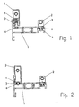
- a profile for example, a window or door rung profile 1 is shown, are attached to the profile joint connector 2 for connection to another profile part, for example, a sprout, support or fighter profile.
- the profile joint connector 2 is formed on a connection side so that it hooks the profile 1 behind.
- This connection side can be provided laterally on the butt connector 2, as is the case in the embodiments on the left side in FIGS. 1 and 2, or on its front side, as is the case with the butt connectors 2 on the right side in FIGS Figures 1 and 2 are arranged.
- a pin 3 is provided, which projects in the direction of the profile 1 and engages in a hole 4 in the profile 1.
- This pin 3 may have a reduced diameter pen tip or a tapered tip.
- the butt connector 2 is spring-loaded via a spring element 5, 6 in the direction of the hooking position between the butt connector 2 and the profile 1.
- a spring for example, a coil spring 5 is arranged in the joint connector 2, which holds the pin 3 in the butt connector 2 resiliently.
- the pin 3 is fixedly arranged in the butt connector 2 and is arranged on the projecting part of the pin 3, a spring element 6, which in the example shown from an O-ring seal, made of a resilient material, such as rubber, consists.
- the pin 3 can be fixedly inserted into the connector 2 or formed in one piece therewith.
- the left side in Figure 2 arranged embodiment of the butt connector 2 corresponds to the right in Figure 1 arranged butt connector and also has an O-ring seal 6, which surrounds the front end of the pin 3.
- the embodiment of the joint connector 2 shown on the right in FIG. 2 is identical to the exemplary embodiment shown in FIG. 1 below.
Landscapes
- Engineering & Computer Science (AREA)
- Civil Engineering (AREA)
- Structural Engineering (AREA)
- Joining Of Corner Units Of Frames Or Wings (AREA)
- Paper (AREA)
- Crushing And Grinding (AREA)
- Window Of Vehicle (AREA)
- Connector Housings Or Holding Contact Members (AREA)
- Specific Sealing Or Ventilating Devices For Doors And Windows (AREA)
Description
- Die Erfindung betrifft einen Profilstoßverbinder, insbesondere für Fenster- oder Türrahmen zum Einklipsen, Eindrehen oder Einhängen in ein Profil mit einer das Profil hinterhakenden Verbindungsseite.
- Ein derartiger Profilstoßverbinder dient zum Herstellen einer Stoßverbindung zwischen zwei Profilen, insbesondere dem Rahmenprofil und dem Sprossen-, Stützen- oder Kämpferprofil eines Fensters oder einer Tür.
- Es ist bekannt, Profilstoßverbinder mit einer das Profil hinterhakenden Verbindungsseite so auszubilden, daß der Stoßverbinder an seiner Verbindungsseite in das Profil eingeklipst, eingedreht oder eingehängt werden kann. In dieser Weise wird der Stoßverbinder am Profil angeschlossen und vorfixiert ohne daß er von der Profilstirnseite her aufgeschoben werden muß.
- In der US-A-5618127 ist ein profilstoßverbinder mit einer das profil hinterhakenden Anschlußseite beschrieben.
- Bei allen derartigen Stoßverbindern zum Einklipsen, Eindrehen oder Einhängen in das Profil erfolgt die endgültige Fixierung mit Hilfe von Schrauben, die so in den Stoßverbinder eingeschraubt werden, daß eine Gegenkraft erzeugt und dadurch ein Formschluß bewirkt wird. Dadurch wird die Hinterhakung gesichert und wird gleichzeitig ein axiales Verschieben in Profillängsrichtung verhindert.
- Die feste endgültige Fixierung des zu verbindenden Profilteils erfolgt über das Einbringen von Stiften oder Schrauben in das zu verbindende Profilteil und den Stoßverbinder. Die Abmessungen sind dabei so gewählt, daß die beiden Profile dadurch mit mechanischer Spannung gegeneinander gezogen sind.
- An den Stellen, an denen der Stoßverbinder innen an der Innenseite der Hohlkammer des zu verbindenden Profils anliegt, erfolgt in der Regel eine Verklebung.
- Die bekannten Profilstoßverbinder der oben beschriebenen Art haben den Nachteil, daß sie angeschraubt, das heißt mit Schrauben am Profil festgelegt werden müssen, und eine Positionierung ohne Referenzmarkierung erfolgt.
- Die der Erfindung zugrunde liegende Aufgabe besteht daher darin, einen Profilstoßverbinder der eingangs genannten Art zu schaffen, bei dem ein Verschrauben nicht mehr notwendig ist.
- Diese Aufgabe wird gemäß der Erfindung durch die Ausbildung gelöst, die im Patentanspruch 1 angegeben ist.
- Bei dem erfindungsgemäßen Profilstoßverbinder wird durch das Federelement eine selbsttätige Fixierung am Profil sichergestellt, so daß eine Verschraubung nicht mehr nötig ist, und wird durch das im Profil vorgesehene Loch, in das der Stift eingreift, eine genaue Positionierung erreicht. Da die Bearbeitung von Profilen zunehmend in Profilbearbeitungszentren erfolgt, lassen sich die notwendigen Löcher sehr exakt und nahezu ohne zusätzlichen Aufwand einbringen, was eine sehr genaue Positionierung des Stoßverbinders erlaubt. Hierdurch kann insbesondere eine maschinelle Positionierung zur automatischen Fertigung beispielsweise von Fenster- oder Türrahmen erreicht werden.
- Besonders bevorzugte Ausführungsformen des erfindungsgemäßen Profilstoßverbinders sind Gegenstand der Patentansprüche 2 bis 5.
- Im Folgenden werden anhand der zugehörigen Zeichnungen besonders bevorzugte Ausführungsbeispiele des erfindungsgemäßen Profilstoßverbinders näher beschrieben.
- Es zeigen
- Figur 1 in einer Schnittansicht zwei Ausführungsbeispiele des erfindungsgemäßen Profilstoßverbinders im am Profil montierten Zustand und
- Figur 2 in einer Figur 1 entsprechenden Ansicht ein weiteres Ausführungsbeispiel des erfindungsgemäßen Profilstoßverbinders im am Profil montierten Zustand.
- In den Figuren 1 und 2 ist jeweils ein Profil beispielsweise ein Fenster- oder Türsprossenprofil 1 dargestellt, an dem Profilstoßverbinder 2 zum Verbinden mit einem weiteren Profilteil beispielsweise einem Sprossen-, Stützen- oder Kämpferprofil angebracht sind.
- Wie es in der Zeichnung im Einzelnen dargestellt ist, ist der Profilstoßverbinder 2 an einer Anschlußseite so ausgebildet, daß er das Profil 1 hinterhakt. Diese Anschlußseite kann seitlich am Stoßverbinder 2, wie es bei den Ausführungsbeispielen an der linken Seite in den Figuren 1 und 2 der Fall ist, oder an dessen Stirnseite vorgesehen sein, wie es bei den Stoßverbindern 2 der Fall, die an der rechten Seite in den Figuren 1 und 2 angeordnet sind.
- An der Stirnseite der Stoßverbinder 2 ist ein Stift 3 vorgesehen, der in Richtung auf das Profil 1 vorsteht und in ein Loch 4 im Profil 1 eingreift. Dieser Stift 3 kann eine Stiftspitze mit verringertem Durchmesser oder eine konisch zulaufende Spitze aufweisen.
- Der Stoßverbinder 2 ist über ein Federelement 5, 6 in Richtung auf die Verhakungsposition zwischen dem Stoßverbinder 2 und dem Profil 1 federbeaufschlagt.
- Bei dem linken, in Figur 1 dargestellten Ausführungsbeispiel des Stoßverbinders 2 ist im Stoßverbinder 2 eine Feder, beispielsweise eine Schraubenfeder 5 angeordnet, die den Stift 3 im Stoßverbinder 2 federnd hält.
- Bei den beiden Ausführungsbeispielen in Figur 2 ist der Stift 3 fest im Stoßverbinder 2 angeordnet und ist auf dem vorstehenden Teil des Stiftes 3 ein Federelement 6 angeordnet, das bei dem dargestellten Beispiel aus einer O-Ringdichtung, aus einem federelastischen Material, beispielsweise aus Gummi, besteht. Bei diesem Ausführungsbeispiel kann der Stift 3 fest in den Verbinder 2 eingesetzt oder in einem Stück damit ausgebildet sein.
- Bei der Ausbildung des Federelements 6 in Form einer O-Ringdichtung ergibt sich der weitere Vorteil, daß das Loch 4 zusätzlich abgedichtet werden kann und dadurch ein Eindringen von Wasser in die Hohlkammer des Profils 1 vermieden werden kann.
- Das in Figur 2 links angeordnete Ausführungsbeispiel des Stoßverbinders 2 entspricht dem in Figur 1 rechts angeordneten Stoßverbinder und weist gleichfalls eine O-Ringdichtung 6 auf, die das vordere Ende des Stiftes 3 umgibt.
- Das in Figur 2 rechts dargestellte Ausführungsbeispiel des Stoßverbinders 2 ist mit dem in Figur 1 unten dargestellten Ausführungsbeispiel identisch.
- Die Montage der oben beschriebenen Ausführungsbeispiele des erfindungsgemäßen Stoßverbinders 2 erfolgt dadurch, daß diese durch Einklipsen, Einhängen oder Eindrehen am Profil 1 angebracht werden, wobei gleichzeitig der Stift 3 in das an einer genau positionierten Stelle im Profil vorher vorgesehene Loch eingreift und die Hinterhakungsposition durch das jeweilige Federelement 5, 6 gesichert wird. Dabei ist durch den Eingriff des Stiftes 3 in das Loch 4 gleichzeitig eine exakte Referenzpositionierung sichergestellt.
Claims (5)
- Profilstoßverbinder (2), insbesondere für Fenster- oder Türrahmen, zum Einklipsen, Eindrehen oder Einhängen in ein Profil (1), mit einer Anschlußseite, mit der der Profilstoßverbinder in eingeklipsten, eingedrehten oder eingehängten Zustand das Profil (1) hinterhakt, und mit einem Federelement (5,6), das den Verbinder (2) in eingeklipsten, eingedrehten oder eingehängten Zustand in Richtung auf die Verhakungsposition zwischen dem Verbinder (2) und dem Profil (1) federbeaufschlagt,
gekennzeichnet durch
einen an einer Stirnseite des Stoßverbinders vorstehenden Stift (3), der in eingeklipsten, eingedrehten oder eingehängten Zustand des Profilstoβverbinders in Richtung auf das Profil (1) vorsteht und zur Positionierung des Verbinders in ein Loch (4) im Profil eingreifen kann. - Profilstoßverbinder nach Anspruch 1, dadurch gekennzeichnet, daß der Stift (3) fest am Verbinder (2) angeordnet ist und das Federelement (6) auf dem vorstehenden Teil des Stiftes (2) sitzt.
- Profilstoßverbinder nach Anspruch 2, dadurch gekennzeichnet, daß das Federelement (5, 6) eine O-Ringdichtung aus einem federelastischen Material ist.
- Profilstoßverbinder nach Anspruch 3, dadurch gekennzeichnet, daß das federelastische Material Gummi ist.
- Profilstoßverbinder nach Anspruch 1, dadurch gekennzeichnet, daß der Stift (3) gegen das Federelement (5) federnd in den Verbinder (2) eingesetzt ist.
Applications Claiming Priority (2)
| Application Number | Priority Date | Filing Date | Title |
|---|---|---|---|
| DE10151061A DE10151061A1 (de) | 2001-10-16 | 2001-10-16 | Profilstoßverbinder |
| DE10151061 | 2001-10-16 |
Publications (3)
| Publication Number | Publication Date |
|---|---|
| EP1302618A2 EP1302618A2 (de) | 2003-04-16 |
| EP1302618A3 EP1302618A3 (de) | 2004-02-11 |
| EP1302618B1 true EP1302618B1 (de) | 2006-03-29 |
Family
ID=7702688
Family Applications (1)
| Application Number | Title | Priority Date | Filing Date |
|---|---|---|---|
| EP02020538A Expired - Lifetime EP1302618B1 (de) | 2001-10-16 | 2002-09-16 | Profilstossverbinder |
Country Status (3)
| Country | Link |
|---|---|
| EP (1) | EP1302618B1 (de) |
| AT (1) | ATE321928T1 (de) |
| DE (2) | DE10151061A1 (de) |
Families Citing this family (2)
| Publication number | Priority date | Publication date | Assignee | Title |
|---|---|---|---|---|
| DE102014111089A1 (de) * | 2014-08-05 | 2016-02-11 | Hueck Gmbh & Co. Kg | Profilanordnung |
| CN110541660A (zh) * | 2019-08-28 | 2019-12-06 | 合肥四周建筑装饰有限公司 | 一种防水易拆卸的门窗 |
Family Cites Families (9)
| Publication number | Priority date | Publication date | Assignee | Title |
|---|---|---|---|---|
| DE4106282C2 (de) * | 1991-02-28 | 1998-02-26 | Pax Gmbh | Mechanische Verbindung von mit einschiebbaren metallischen Verstärkungshohlprofilen versehenen Kunststoffhohlprofilen, insbesondere für Fenster-, Tür- od. dgl. -Rahmen |
| DE4126991C2 (de) * | 1991-08-15 | 1995-09-14 | Leitner Gmbh | Stab mit einer Verbindungsanordnung |
| DE4244603A1 (de) * | 1992-12-31 | 1994-07-07 | Linder Gmbh A | Klemmverbinder |
| DE4306420A1 (de) * | 1993-03-02 | 1994-09-08 | Schueco Int Kg | T-Verbindung zwischen zwei Profilen |
| DE4328832C2 (de) * | 1993-08-27 | 1995-11-23 | F & T Form & Technik | Aus Profilteilen bestehendes Gestell |
| DE19641500C2 (de) * | 1996-10-09 | 2001-10-25 | Siegfried Aichner | Vorrichtung zum lösbaren Verbinden von Profilstäben |
| DE19842896C2 (de) * | 1998-09-18 | 2001-11-29 | Fms Foerder Und Montage System | Verbindungseinrichtung zum Verbinden von Profilstäben |
| DE29921735U1 (de) * | 1999-12-02 | 2000-04-13 | STEELBOX GmbH, 10585 Berlin | Bausatz zum Herstellen von lösbaren Verbindungen für langdimensionierte, strangförmige, gerasterte Bauteile, für die Herstellung von sich mehrdimensional erstreckenden, strukturierten Körpern, unter Verwendung in die Bauteile eingreifender Verbindungselemente und damit hergestellte strukturierte Baukörper |
| DE20109341U1 (de) * | 2001-06-05 | 2001-08-30 | A. Fickenscher & Söhne GmbH & Co., 95145 Oberkotzau | Pfostenverbinder zur Verbindung von Pfosten und Sprossen im Blendrahmen in vertieften Fenstersystemen |
-
2001
- 2001-10-16 DE DE10151061A patent/DE10151061A1/de not_active Withdrawn
-
2002
- 2002-09-16 EP EP02020538A patent/EP1302618B1/de not_active Expired - Lifetime
- 2002-09-16 AT AT02020538T patent/ATE321928T1/de active
- 2002-09-16 DE DE50206206T patent/DE50206206D1/de not_active Expired - Lifetime
Also Published As
| Publication number | Publication date |
|---|---|
| DE10151061A1 (de) | 2003-04-30 |
| EP1302618A2 (de) | 2003-04-16 |
| EP1302618A3 (de) | 2004-02-11 |
| DE50206206D1 (de) | 2006-05-18 |
| ATE321928T1 (de) | 2006-04-15 |
Similar Documents
| Publication | Publication Date | Title |
|---|---|---|
| DE3687293T2 (de) | Vollstaendig gegliederte lagerungsvorrichtung. | |
| DE202013101520U1 (de) | Duschtür-Baugruppe | |
| EP0389954B1 (de) | Vorrichtung zum Führen und Halten von Leiterplatten | |
| DE202010013011U1 (de) | Befestigungsanordnung für die Montage von Beschlagteilen | |
| EP0582258B1 (de) | Befestigungsvorrichtung | |
| DE3437430C1 (de) | Stoßverbindung eines Kämpferprofils mit einem Rahmen- oder Sprossenprofil für wärmegedämmte Fenster, Türen o.dgl. | |
| DE3107725A1 (de) | Isolierende verbindungsvorrichtung fuer bauplatten, insbesondere glasscheiben tragende zweiteilige metallrahmen | |
| EP2357367A1 (de) | Montagesysteme für Platten und Rohre | |
| DE19522044A1 (de) | Eck- oder T-Verbindung an Rahmen oder Gestellen | |
| EP1898041B1 (de) | Vorrichtung und Verfahren zum Befestigen von Aufsatzelementen auf bauseitigen Rahmensystemen | |
| DE10151061A1 (de) | Profilstoßverbinder | |
| EP2538007A2 (de) | System mit einem Profil und einem Beschlagteil | |
| DE202010013558U1 (de) | Scharnier für ein Insekten- und/oder Pollenschutzgitter | |
| EP0291973B1 (de) | Verbindungsstück für zwei winklig aneinanderstossende Profilstäbe von Fenster oder Türrahmen | |
| CH687716A5 (de) | Beschlag. | |
| DE10150632A1 (de) | Verfahren zum Herstellen eines Wischarms | |
| DE102020103627A1 (de) | Federstiftstossverbinder | |
| DE102020126347B3 (de) | Abstandhalter, Führungsschiene für einen Raffstore oder eine Jalousie sowie Raffstore und Jalousie und Verfahren hierfür | |
| AT513377B1 (de) | Kunststofffenster | |
| DE19832879C2 (de) | Seilzug-Fensterheber für Fahrzeuge | |
| EP1469157A1 (de) | Schliessleiste | |
| DE19524648A1 (de) | U-förmige Aufklipsgleitmutter | |
| EP4261446A1 (de) | Befestigungsvorrichtung, anordnung mit einer befestigungsvorrichtung und verfahren zum herstellen einer befestigungsvorrichtung | |
| DE102023136225A1 (de) | T-Verbindung und Verfahren zur Montage einer T-Verbindung | |
| DE102004043973B3 (de) | Verfahren zur Verbindung von Baugruppen einer Beschlaganordnung in einer Beschlagteilnut eines Tür- oder Fensterflügels |
Legal Events
| Date | Code | Title | Description |
|---|---|---|---|
| PUAI | Public reference made under article 153(3) epc to a published international application that has entered the european phase |
Free format text: ORIGINAL CODE: 0009012 |
|
| AK | Designated contracting states |
Designated state(s): AT BE BG CH CY CZ DE DK EE ES FI FR GB GR IE IT LI LU MC NL PT SE SK TR |
|
| AX | Request for extension of the european patent |
Extension state: AL LT LV MK RO SI |
|
| PUAL | Search report despatched |
Free format text: ORIGINAL CODE: 0009013 |
|
| AK | Designated contracting states |
Kind code of ref document: A3 Designated state(s): AT BE BG CH CY CZ DE DK EE ES FI FR GB GR IE IT LI LU MC NL PT SE SK TR |
|
| AX | Request for extension of the european patent |
Extension state: AL LT LV MK RO SI |
|
| RIC1 | Information provided on ipc code assigned before grant |
Ipc: 7E 06B 3/964 A Ipc: 7E 06B 3/96 B |
|
| 17P | Request for examination filed |
Effective date: 20040407 |
|
| GRAP | Despatch of communication of intention to grant a patent |
Free format text: ORIGINAL CODE: EPIDOSNIGR1 |
|
| GRAS | Grant fee paid |
Free format text: ORIGINAL CODE: EPIDOSNIGR3 |
|
| AKX | Designation fees paid |
Designated state(s): AT BE BG CH CY CZ DE DK EE ES FI FR GB GR IE IT LI LU MC NL PT SE SK TR |
|
| GRAA | (expected) grant |
Free format text: ORIGINAL CODE: 0009210 |
|
| AK | Designated contracting states |
Kind code of ref document: B1 Designated state(s): AT BE BG CH CY CZ DE DK EE ES FI FR GB GR IE IT LI LU MC NL PT SE SK TR |
|
| PG25 | Lapsed in a contracting state [announced via postgrant information from national office to epo] |
Ref country code: SK Free format text: LAPSE BECAUSE OF FAILURE TO SUBMIT A TRANSLATION OF THE DESCRIPTION OR TO PAY THE FEE WITHIN THE PRESCRIBED TIME-LIMIT Effective date: 20060329 Ref country code: IE Free format text: LAPSE BECAUSE OF FAILURE TO SUBMIT A TRANSLATION OF THE DESCRIPTION OR TO PAY THE FEE WITHIN THE PRESCRIBED TIME-LIMIT Effective date: 20060329 |
|
| REG | Reference to a national code |
Ref country code: GB Ref legal event code: FG4D Free format text: NOT ENGLISH |
|
| REG | Reference to a national code |
Ref country code: CH Ref legal event code: EP |
|
| REG | Reference to a national code |
Ref country code: IE Ref legal event code: FG4D Free format text: LANGUAGE OF EP DOCUMENT: GERMAN |
|
| REF | Corresponds to: |
Ref document number: 50206206 Country of ref document: DE Date of ref document: 20060518 Kind code of ref document: P |
|
| REG | Reference to a national code |
Ref country code: CH Ref legal event code: NV Representative=s name: E. BLUM & CO. PATENTANWAELTE |
|
| GBT | Gb: translation of ep patent filed (gb section 77(6)(a)/1977) |
Effective date: 20060518 |
|
| PG25 | Lapsed in a contracting state [announced via postgrant information from national office to epo] |
Ref country code: BG Free format text: LAPSE BECAUSE OF FAILURE TO SUBMIT A TRANSLATION OF THE DESCRIPTION OR TO PAY THE FEE WITHIN THE PRESCRIBED TIME-LIMIT Effective date: 20060629 Ref country code: DK Free format text: LAPSE BECAUSE OF FAILURE TO SUBMIT A TRANSLATION OF THE DESCRIPTION OR TO PAY THE FEE WITHIN THE PRESCRIBED TIME-LIMIT Effective date: 20060629 |
|
| PG25 | Lapsed in a contracting state [announced via postgrant information from national office to epo] |
Ref country code: ES Free format text: LAPSE BECAUSE OF FAILURE TO SUBMIT A TRANSLATION OF THE DESCRIPTION OR TO PAY THE FEE WITHIN THE PRESCRIBED TIME-LIMIT Effective date: 20060710 |
|
| REG | Reference to a national code |
Ref country code: SE Ref legal event code: TRGR |
|
| PG25 | Lapsed in a contracting state [announced via postgrant information from national office to epo] |
Ref country code: PT Free format text: LAPSE BECAUSE OF FAILURE TO SUBMIT A TRANSLATION OF THE DESCRIPTION OR TO PAY THE FEE WITHIN THE PRESCRIBED TIME-LIMIT Effective date: 20060829 |
|
| PG25 | Lapsed in a contracting state [announced via postgrant information from national office to epo] |
Ref country code: MC Free format text: LAPSE BECAUSE OF NON-PAYMENT OF DUE FEES Effective date: 20060930 |
|
| ET | Fr: translation filed | ||
| REG | Reference to a national code |
Ref country code: IE Ref legal event code: FD4D |
|
| PLBE | No opposition filed within time limit |
Free format text: ORIGINAL CODE: 0009261 |
|
| STAA | Information on the status of an ep patent application or granted ep patent |
Free format text: STATUS: NO OPPOSITION FILED WITHIN TIME LIMIT |
|
| 26N | No opposition filed |
Effective date: 20070102 |
|
| REG | Reference to a national code |
Ref country code: CH Ref legal event code: PFA Owner name: NORSK HYDRO ASA Free format text: NORSK HYDRO ASA#BYGDOY ALLE 2#0257 OSLO 2 (NO) -TRANSFER TO- NORSK HYDRO ASA#BYGDOY ALLE 2#0257 OSLO 2 (NO) |
|
| PG25 | Lapsed in a contracting state [announced via postgrant information from national office to epo] |
Ref country code: CZ Free format text: LAPSE BECAUSE OF FAILURE TO SUBMIT A TRANSLATION OF THE DESCRIPTION OR TO PAY THE FEE WITHIN THE PRESCRIBED TIME-LIMIT Effective date: 20060329 Ref country code: GR Free format text: LAPSE BECAUSE OF FAILURE TO SUBMIT A TRANSLATION OF THE DESCRIPTION OR TO PAY THE FEE WITHIN THE PRESCRIBED TIME-LIMIT Effective date: 20060630 |
|
| PG25 | Lapsed in a contracting state [announced via postgrant information from national office to epo] |
Ref country code: FI Free format text: LAPSE BECAUSE OF FAILURE TO SUBMIT A TRANSLATION OF THE DESCRIPTION OR TO PAY THE FEE WITHIN THE PRESCRIBED TIME-LIMIT Effective date: 20060329 Ref country code: EE Free format text: LAPSE BECAUSE OF FAILURE TO SUBMIT A TRANSLATION OF THE DESCRIPTION OR TO PAY THE FEE WITHIN THE PRESCRIBED TIME-LIMIT Effective date: 20060329 |
|
| PG25 | Lapsed in a contracting state [announced via postgrant information from national office to epo] |
Ref country code: LU Free format text: LAPSE BECAUSE OF NON-PAYMENT OF DUE FEES Effective date: 20060916 Ref country code: TR Free format text: LAPSE BECAUSE OF FAILURE TO SUBMIT A TRANSLATION OF THE DESCRIPTION OR TO PAY THE FEE WITHIN THE PRESCRIBED TIME-LIMIT Effective date: 20060329 |
|
| PG25 | Lapsed in a contracting state [announced via postgrant information from national office to epo] |
Ref country code: CY Free format text: LAPSE BECAUSE OF FAILURE TO SUBMIT A TRANSLATION OF THE DESCRIPTION OR TO PAY THE FEE WITHIN THE PRESCRIBED TIME-LIMIT Effective date: 20060329 |
|
| PGFP | Annual fee paid to national office [announced via postgrant information from national office to epo] |
Ref country code: IT Payment date: 20100923 Year of fee payment: 9 |
|
| PGFP | Annual fee paid to national office [announced via postgrant information from national office to epo] |
Ref country code: CH Payment date: 20110923 Year of fee payment: 10 |
|
| PGFP | Annual fee paid to national office [announced via postgrant information from national office to epo] |
Ref country code: GB Payment date: 20110920 Year of fee payment: 10 Ref country code: SE Payment date: 20110923 Year of fee payment: 10 Ref country code: DE Payment date: 20110923 Year of fee payment: 10 Ref country code: FR Payment date: 20110928 Year of fee payment: 10 Ref country code: AT Payment date: 20110914 Year of fee payment: 10 |
|
| PGFP | Annual fee paid to national office [announced via postgrant information from national office to epo] |
Ref country code: NL Payment date: 20110929 Year of fee payment: 10 |
|
| PGFP | Annual fee paid to national office [announced via postgrant information from national office to epo] |
Ref country code: BE Payment date: 20110914 Year of fee payment: 10 |
|
| BERE | Be: lapsed |
Owner name: *NORSK HYDRO ASA Effective date: 20120930 |
|
| REG | Reference to a national code |
Ref country code: NL Ref legal event code: V1 Effective date: 20130401 |
|
| PG25 | Lapsed in a contracting state [announced via postgrant information from national office to epo] |
Ref country code: SE Free format text: LAPSE BECAUSE OF NON-PAYMENT OF DUE FEES Effective date: 20120917 |
|
| REG | Reference to a national code |
Ref country code: SE Ref legal event code: EUG Ref country code: CH Ref legal event code: PL |
|
| REG | Reference to a national code |
Ref country code: AT Ref legal event code: MM01 Ref document number: 321928 Country of ref document: AT Kind code of ref document: T Effective date: 20120916 |
|
| GBPC | Gb: european patent ceased through non-payment of renewal fee |
Effective date: 20120916 |
|
| REG | Reference to a national code |
Ref country code: FR Ref legal event code: ST Effective date: 20130531 |
|
| PG25 | Lapsed in a contracting state [announced via postgrant information from national office to epo] |
Ref country code: GB Free format text: LAPSE BECAUSE OF NON-PAYMENT OF DUE FEES Effective date: 20120916 Ref country code: CH Free format text: LAPSE BECAUSE OF NON-PAYMENT OF DUE FEES Effective date: 20120930 Ref country code: BE Free format text: LAPSE BECAUSE OF NON-PAYMENT OF DUE FEES Effective date: 20120930 Ref country code: LI Free format text: LAPSE BECAUSE OF NON-PAYMENT OF DUE FEES Effective date: 20120930 Ref country code: DE Free format text: LAPSE BECAUSE OF NON-PAYMENT OF DUE FEES Effective date: 20130403 Ref country code: AT Free format text: LAPSE BECAUSE OF NON-PAYMENT OF DUE FEES Effective date: 20120916 |
|
| PG25 | Lapsed in a contracting state [announced via postgrant information from national office to epo] |
Ref country code: NL Free format text: LAPSE BECAUSE OF NON-PAYMENT OF DUE FEES Effective date: 20130401 Ref country code: IT Free format text: LAPSE BECAUSE OF NON-PAYMENT OF DUE FEES Effective date: 20120916 Ref country code: FR Free format text: LAPSE BECAUSE OF NON-PAYMENT OF DUE FEES Effective date: 20121001 |
|
| REG | Reference to a national code |
Ref country code: DE Ref legal event code: R119 Ref document number: 50206206 Country of ref document: DE Effective date: 20130403 |
|
| REG | Reference to a national code |
Ref country code: DE Ref legal event code: R082 Ref document number: 50206206 Country of ref document: DE Representative=s name: KOTITSCHKE & HEURUNG PARTNERSCHAFT, DE |