EP1298366A2 - Joint pour arbre tournant et turbine - Google Patents
Joint pour arbre tournant et turbine Download PDFInfo
- Publication number
- EP1298366A2 EP1298366A2 EP02021351A EP02021351A EP1298366A2 EP 1298366 A2 EP1298366 A2 EP 1298366A2 EP 02021351 A EP02021351 A EP 02021351A EP 02021351 A EP02021351 A EP 02021351A EP 1298366 A2 EP1298366 A2 EP 1298366A2
- Authority
- EP
- European Patent Office
- Prior art keywords
- leaf seal
- pressure
- seal ring
- rotation shaft
- leaf
- Prior art date
- Legal status (The legal status is an assumption and is not a legal conclusion. Google has not performed a legal analysis and makes no representation as to the accuracy of the status listed.)
- Granted
Links
Images


Classifications
-
- F—MECHANICAL ENGINEERING; LIGHTING; HEATING; WEAPONS; BLASTING
- F16—ENGINEERING ELEMENTS AND UNITS; GENERAL MEASURES FOR PRODUCING AND MAINTAINING EFFECTIVE FUNCTIONING OF MACHINES OR INSTALLATIONS; THERMAL INSULATION IN GENERAL
- F16J—PISTONS; CYLINDERS; SEALINGS
- F16J15/00—Sealings
- F16J15/16—Sealings between relatively-moving surfaces
- F16J15/32—Sealings between relatively-moving surfaces with elastic sealings, e.g. O-rings
- F16J15/3284—Sealings between relatively-moving surfaces with elastic sealings, e.g. O-rings characterised by their structure; Selection of materials
- F16J15/3292—Lamellar structures
Definitions
- the present invention relates to a shaft seal structure suitable for application to rotation shafts and the like used in large fluidic machines such as gas turbines, steam turbines, compressors and pumps, and relates also to a turbine that converts fluid thermal energy into rotational energy for generating a motion power, and relates in particular to a shaft seal structure that can be applied to a rotation shaft of the turbine.
- a shaft seal structure is provided around the rotation shaft for reducing leakage of combustion gas from the high-pressure-region to the low-pressure-region.
- An example of such a shaft seal is a leaf seal 1 shown in FIG. 18.
- the leaf seal 1 comprises a plurality of layers of planar plates 3, having a predetermined width dimension in the axial direction of the rotation shaft 2, arranged in the circumferential direction of the rotation shaft 2.
- the base section of the planar plates 3 of the outer periphery is fixed to a leaf seal ring 5 by means of a brazed section 4, and the tip end of the planar plates 3 is on the inner periphery, and is made to contact the rotation shaft 2 at a given pre-loading value.
- the tip of each planar plate 3, as shown in FIGS. 18 and 19, slidably contacts the peripheral surface of the rotation shaft 2 at an acute angle with the peripheral surface of the rotation shaft with respect to the rotation direction of the rotation shaft 2 (shown by the arrow d in the diagram).
- the planar plate 3 attached to the leaf seal ring 5, as described above, serves as a seal on the outer peripheral surface of the rotation shaft 2, and divides the surrounding space of the rotation shaft 2 into a high pressure region and a low pressure region.
- planar plates 3 of the leaf seal ring 5 are surrounded laterally by a high-pressure-region plate 7 in the high-pressure-region and by a low-pressure-region plate 8 in the low-pressure-region to act as guiding plates to operate in the pressurizing direction.
- An object of the present invention is to provide a shaft seal structure which can reduce the volume of gas leaking from the high-pressure-region to the low-pressure-retion and to control the wear between the planar plates and the rotation shaft.
- Another object of the present invention is to provide a turbine having such a seal structure.
- the present invention provides a shaft seal structure for blocking a fluid flowing in an axial direction through a ring-shaped space formed between a rotation shaft and a stator section, comprising: a leaf seal ring retained inside the stator section; and a plurality of planar plates separated from each other in a peripheral direction of the rotation shaft, in such a way that an outer peripheral end of each planar plate is fixed inside the leaf seal ring and a tip of each planar plate, expanding in width direction in the axial direction, slidably contacts a peripheral surface of the rotation shaft at an acute angle; wherein provided are pushing members disposed between the stator section and the leaf seal ring for pushing the leaf seal ring towards an outer radial direction to separate the leaf seal ring away from the rotation shaft; and pressure guiding grooves for guiding a fluid pressure from a high-pressure-region to a space between an outer peripheral surface of the leaf seal ring and an inner peripheral surface of the stator section through a boundary formed by the planar plates.
- the leaf seal ring is forced towards outer radial side of the leaf seal ring, the tips of the planar plates provided on the leaf seal ring and the peripheral surface of the rotation shaft are kept in the non-contact state; thus, it is possible to prevent the wear between the planar plates and the rotation shaft caused by the rotation of the rotation shaft.
- the differential sealing pressure is high, the pressure of the combustion gas is guided from the pressure guiding grooves to the space between the outer peripheral surface of the leaf seal ring and the inner peripheral surface of the stator section to absorb the pushing force of the leaf springs. Therefore, the leaf seal ring is moved towards the inner peripheral region to come closer to the rotation shaft. Therefore, it is possible to reduce the space generated by thermal expansion and reducing the amount of gas leakage through the space between the rotation shaft and the tips of the leaf springs from the high-pressure-region to the low-pressure-region.
- the pushing member may be provided in the leaf seal ring side.
- the pushing members may be provided easily between the stator section and the leaf seal ring, without undertaking special fabrication of interior of the stator section. Also, because the pushing members provided on the leaf seal side can be detached more easily than the pushing members attached to the stator section, when a pushing member is deteriorated or damaged, maintenance and other work on the pushing members are facilitated.
- the pushing member may be provided in a holding members that are separated from the stator section, and the holding member may be provided in the stator section region.
- the foregoing shaft seal structure is characterized in that in any one of the shaft seal structures, the pushing member is provided in the high-pressure-region as well as in the low-pressure-region while putting each planar plates between the pushing members.
- the leaf seal ring can be floated stably towards the outer peripheral side of the rotation shaft so that, when the rotation shaft is operated at low speeds, it is possible to ensure that the tip of the planar plates do not contact the peripheral surface of the rotation shaft. Also, compared with the case in which the pushing member is provided only on one side of the planar plates, the load exerted by the leaf seal ring on the pushing member can be reduced to a half. Therefore, degradation caused by the load on the pushing member by the leaf seal ring can be controlled.
- a turbine according to a fifth aspect of the present invention it is characterized in that a high-temperature-high-pressure fluid is introduced into a turbine casing, a shaft seal structure is provided to a turbine for generating a motion force by converting a thermal fluid energy to a kinetic rotational force by blowing the fluid to a rotor blade which is attached to the rotation shaft which is slidably supported.
- a turbine is characterized in having shaft seals which can obtain the same effect as the effects obtained by the above-mentioned seal structure.
- the shaft seal structure and the turbine having the shaft seal structure has the following advantages.
- the shaft seal structure is based on providing, between the stator section and the leaf seal ring, pushing members that force the leaf seal ring to move away from the rotation shaft in the radial direction, and pressure guiding grooves that guide the pressure of the high-pressure-region to a space between the outer peripheral surface of the leaf seal ring and the stator section, with the planar plates serving as the boundary.
- the leaf seal ring is forced by the pushing members towards outer radial side of the leaf seal ring inside the stator section, so that the tips of the planar plates provided on the leaf seal ring and the peripheral surface of the rotation shaft are kept in the non-contact state, thus preventing the wear between the planar plates and the rotation shaft caused by the rotation of the rotation shaft.
- the pressure of the combustion gas is guided from the pressure guiding grooves to the space between the outer peripheral surface of the leaf seal ring and the inner peripheral surface of the stator section to absorb the pushing force of the leaf springs, so that the leaf seal ring is moved towards the inner peripheral side to come closer to the rotation shaft, thereby enabling the tips of the planar plates to contact the peripheral surface of the rotation shaft at a specific pressure, thereby reducing the amount of gas leakage through the space between the rotation shaft and the tips of the leaf springs from the high-pressure-region to the low-pressure-region.
- the shaft seal structure is characterized in that the pushing members are located on the leaf seal ring side, and therefore, by attaching this leaf seal ring to an existing stator section that does not have pushing members, pushing members may be provided between the stator section and leaf seal ring without undertaking special fabrication of the interior of the stator section.
- the pushing members provided on the leaf seal side can be detached more easily than the pushing members attached to the stator section, when a pushing member is deteriorated or damaged, maintenance and other work on the pushing members are facilitated.
- the pushing member is provided in a holding member that is separated from the stator section, and the holding member is provided in the stator section side, when the pushing members are to be installed, the pushing members between the leaf seal ring and the stator section may be provided simply by attaching the holding section that holds the pushing member to the stator section, without the need to specially fabricate the interior of the stator section for attaching the pushing member directly. Also, if a pushing member is deteriorated or damaged, only the holding member holding the relevant pushing member needs to be detached from the stator section so that maintenance of pushing member can be performed efficiently.
- a fourth aspect of the present invention it is characterized in that, in the shaft seal structure, because the pushing members are provided in the high-pressure-region as well as in the low-pressure-region, with the planar plates intervening between two pressure regions, the leaf seal ring can be floated stably towards the outer peripheral side of the rotation shaft inside the stator section so that, when the rotation shaft is operated at low speeds, it is possible to ensure that the tips of the planar plates do not touch the peripheral surface of the rotation shaft. Also, compared with the case of providing the pushing member only on one side of the planar plates, the load exerted by the leaf seal ring on the pushing member is reduced to a half so that degradation caused by the load on the pushing member by the leaf seal ring can be controlled.
- a fifth aspect of the present invention it is characterized in that, in the turbine, a fluid is guided at a high temperature and under a high pressure to a casing in such a way to blow the fluid at blades fixed to the rotation shaft rotatably supported inside the casing, so as to generate motion power by converting thermal energy of a fluid to rotational energy having the shaft seal structure, because the turbine is provided with any one of the shaft seal structures described above, beneficial effects of the shaft seal structure are accrued to the turbine to improve its performance.
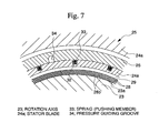
- FIG. 1 shows a schematic structure of the gas turbine.
- a reference numeral 20 indicates to a compressor.
- a reference numeral 21 indicates a burner.
- a reference numeral 22 indicates a turbine.
- the compressor 20 introduces a large volume of air therein and compresses the air.
- a gas turbine utilizes a portion of the motion power obtained from the rotation shaft 23 as a motion power for the compressor 20.
- the burner 21 mixes a fuel into the compressed air from the compressor and combusts the gaseous mixture.
- the turbine 22 admits combustion gas (fluid) generated in the burner 21 and expands the gas so as to blow the expanded gas against the moving blades 23e provided on the rotation shaft 23, thereby converting the thermal energy of the combustion gas into mechanical energy to generate motion power.
- stator blades stator section
- the moving blades 23e and the stator blades 24a are arranged alternatingly on the rotation shaft 23 in the axial direction.
- the moving blades 23e are compressed by the combustion gas flowing in the axial direction of the rotation shaft 23 to rotate the rotation shaft 23, and the rotational energy given to the rotation shaft 23 is transmitted through the shaft end to be used.
- a leaf seal 25 to serve as the shaft seal structure for the purpose of blocking the combustion gas to flow through the ring-shaped space, formed by the stator blades 24a and the rotation shaft 23, in the axial direction of the rotation shaft 23 from the high-pressure-region to the low-pressure-region.
- the leaf seal 25, as shown in FIG. 2, comprises a leaf seal ring 26 retained on the inner section of the stator blades 24a, and a plurality of planar plates 28, whose widths are oriented in the axial direction of the rotation shaft 23 and the leaves are separated from each other by a space 27 therebetween.
- the outer peripheral ends 28a are fixed inside the leaf seal ring 26 and the tips 28b are disposed so as to form an acute angle with the peripheral surface 23a of the rotation shaft 23 to make a slidable contact with the peripheral surface 23a of the rotation shaft 23.
- the leaf seal ring 26 is provided with a high-pressure-region plate 29 on the high-pressure-region and a low-pressure-region plate 30 on the low-pressure-region so as to surround the planar plates 28 therebetween, to serve as pressure guiding plates that are operated in the pressurized direction.
- Each planar plate 28 has a certain elasticity that is dependent on the plate thickness in the axial direction of the rotation shaft, and, in the peripheral direction of the rotation shaft 23, it exhibits soft flexibility.
- FIG. 3 shows a cross section of the leaf seal 25 viewed in the direction of the arrow A in FIG. 2.
- the horizontal cross sectional surface of the leaf seal 26 and the planar plates 28 are T-shaped.
- the leaf seal ring 26 is held inside the T-shaped, concave section 31 of the stator blade 24a by inserting its head section in the outer peripheral side.
- the concave section 31 of the stator blade 24a is made slightly larger than the exterior dimensions of the leaf seal ring 26 so that it is able to move in the axial and radial directions of the rotation shaft 23 inside the concave section 31.
- a hole 32 is formed on the wall surface U' that faces the head section bottom surface U located on the high-pressure-region of the leaf seal ring 26.
- a spring (pushing member) 33 whose one end is fixed to the bottom surface of the hole 32, and the other end is fixed to the head section bottom surface U on the high-pressure-region of the leaf seal ring 26.
- the spring 33 forces the leaf seal ring 26 towards the outer radial direction so as to move it away from the rotation shaft 23.
- FIG. 4 is a cross section of the leaf seal ring 26 viewed in a plane B-B' in FIG. 3.
- a plurality of springs 33 are provided with equal spacing therebetween in the peripheral direction of the rotation shaft 23. Because of this disposition, when the rotation shaft 23 is stopped or operating at low speeds, the leaf seal ring 26 is forced to float inside the concave section 31 of the stator blade 24a due to the pushing force F1 of the springs 33 (i.e., leaf seal ring 26 becomes expanded). Accordingly, when the rotation shaft 23 is stopped or rotating at low speeds, the tips 28b of the planar plates 28 disposed inside the leaf seal ring 26 are in a non-contact state with the peripheral surface 23a of the rotation shaft 23.
- a plurality (four) of pressure guiding grooves 34 of an arch-shape are provided on the head section bottom surface U at an equal interval in the peripheral direction of the leaf seal ring 26.
- FIG. 5 shows a cross section of the leaf seal 25 viewed in a plane C-C'.
- each pressure guiding groove 34 is formed so as to extend along the axial direction of the rotation shaft 23, and communicates with the space 35 between the concave section of the stator blade 24a and the high-pressure-region plate 29 of the leaf seal ring 26.
- the combustion gas between the rotation shaft 23 and the stator blade 24a comes in from the space 35 between the concave section 31 of the stator blade 31a and the leaf seal ring 26, and passes through between the head section bottom surface U of the leaf seal ring 26 and the wall surface U' of the concave section 31 as well as through the pressure guiding grooves 34, and reaches a space between the outer peripheral surface of the leaf seal ring 26 and the inner peripheral surface of the concave section 31.
- a force F2 acts on the upper surface V of the leaf seal ring 26 so that the leaf seal ring 26 is compressed towards the inner periphery, and a force F3 acts on the head section lateral surface V' on the high-pressure-region to press the leaf seal ring 26 towards the low-pressure-region.
- the leaf seal 25 having the structure described above, during the lowspeed operation of the rotation shaft 23, when the differential sealing pressure is low and the planar plates 28 are not being floated sufficiently, the leaf seal ring 26 is pushed towards the outer radial direction by the action of the springs 33, and it is floated in the direction away from the rotation shaft 23 inside the concave section 31 of the stator blade 24a, thereby keeping the tips 28b of the planar plates 28 provided on the leaf seal ring 26 and the peripheral surface 23a of the rotation shaft 23 in the non-contact state. It follows that the wear of the planar plates 23 and the rotation shaft 23 due to the rotation action of the rotation shaft 23 is prevented.
- the pressure in the high-pressure-region is guided from the pressure guiding grooves 34 to the space between the outer peripheral surface of the leaf seal ring 26 and the concave section 31 of the stator blade 24a, causing the pressure of the combustion gas to absorb the pushing force of the leaf spring 33 so as to permit the leaf seal ring 26 to move towards the inner peripheral side to be near the rotation shaft 23, so that the tips 28b of the planar plates 28 contact the peripheral surface 23a of the rotation shaft 23 at a specific pressure.
- the amount of gas leaking through the space between the rotation shaft 23 and the end sections 28b of the planar plates 28 from the high-pressure-region to the low-pressure-region is reduced.
- FIG. 8 shows a cross section of the leaf seal 25 and the stator blade 24a
- FIG. 9 shows a cross section through a plane E-E' of the leaf seal 25 and the stator blade 24a shown in FIG. 8.
- a reference numeral 36 in FIGS. 8, 9 indicates a wave-shaped leaf spring.
- a reference numeral 37 indicates a long hole formed in the concave section 31 of the stator blade 24a for containing the leaf spring 36.
- the leaf seal 25 in the second embodiment utilizes leaf springs 36 instead of the springs 33 used in the leaf seal 25 in the first embodiment.
- each end of the spring 33 to the stator blade 24a and to the leaf seal ring 26, so that by simply inserting the leaf spring 36 in the long hole 37 formed in the stator blade 24a, it is possible to provide the leaf spring 37 between the stator blade 24a and the leaf seal ring 26.
- the leaf seal ring 26 is floated inside the concave section 31 of the stator blade 24a, in the direction to separate it from the rotation shaft 23 by each leaf spring 36, so that the tips 28b of the planar plates 28 and the peripheral surface 23a of the rotation shaft 23 are kept in the non-contact state, thus preventing the wear between the planar plates 28 and the rotation shaft 23 caused by the rotation of the rotation shaft 23.
- the pressure of the combustion gas guided from the pressure guiding grooves 34 to the space between the outer peripheral surface of the leaf seal ring 26 and the inner peripheral surface of the concave section 31of the stator blade 24a absorbs the pushing force of the leaf springs 36, so that the tips 28 of the leaf spring 28 are made contact the peripheral surface 23a of the rotation shaft 23 with a predetermined pressure, thereby reducing the amount of gas leakage through the space between the rotation shaft 23 and the leaf springs 28 from the high-pressure-region to the low-pressure-region.
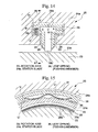
- the leaf seal 25 in the third embodiment is designed so that the springs 35 used in the leaf seal 25 in the first embodiment are held individually in holding members that are separated from the stator blade 24a.
- a reference numeral 38 in FIG. 10 indicates a holding member.
- the holding member 38 comprises a portion obtained by dividing the ring into a plurality of segments in the radial direction, and when attached to the stator blade 24a, forms a concave section 31 for holding the head section of the leaf seal ring 26 in conjunction with the stator blade 24a.
- FIG. 11 is a cross section of the leaf seal 25 and the holding member 34 viewed in a plane F-F' in FIG. 10.
- a bolt insertion hole 39 is provided in each end section for inserting a bolt into the stator blade 24a. Also, between the insertion holes 39, two holes 38a are provided for holding the springs 33 therein.
- a bolt (not shown) is inserted into the insertion hole 39, and the thread section of the bolt is engaged to the bolt hole 39a formed on the stator blade 24a. In so doing, the holding member 38 is attached to the stator blade 24a.
- the springs 33 may be provided between the leaf seal ring 26 and the stator blade 24a along the peripheral direction of the rotation shaft 23 by following a similar procedure to attach a plurality of holding sections 38 to the stator blade 24a.
- springs 33 may be provided between the leaf seal ring 26 and the stator blade 24a simply by attaching the holding members 38 that hold respective springs 33 to the stator blade 24a. Also, compared with the case of fabricating holes 32 or long holes 37 in the stator blade 24a, holes 38a can be easily fabricated. Further, if a spring 33 is deteriorated or damaged, only the holding member holding that spring must be removed from the stator blade 24a so that work of maintaining the springs 33 is efficient.
- the leaf seal ring 26 is floated inside the concave section 31 in the direction to move it away from the rotation shaft 23 due to the action of the springs 33 so that the tips of the planar plates 28 and the peripheral surface of the rotation shaft 23 are maintained in the non-contact state, thus enabling to prevent the wear of the planar plates 28 and the rotation shaft 23 caused by the rotation of the rotation shaft 23.
- a leaf springs 36 may be used instead of the springs 33, similar to the case of the leaf seal 25 in the second embodiment.
- the number of insertion holes 39 and the springs 33 provided in each holding member 38 must not be limited to two, such that any number of parts need for the application may be provided.
- the length of the holding member 38 may be set to any length required.
- the leaf seal 25 in the fourth embodiment is provided with springs 33 on the head section bottom surface U in the high-pressure-region of the leaf seal ring 26 in the leaf seal 25 presented in the first embodiment.
- a reference numeral 40 in FIG. 12 indicates a hole formed in the head section bottom surface U of the leaf seal ring 26.
- a spring 33 is provided in a hole 40.
- the holes 40 and the springs 33, as shown in FIG. 13, are provided in plurality along the peripheral direction of the leaf seal ring 26.
- springs 33 may be provided between the stator blade 24a and the leaf seal ring 26, without having the concave section 31 of the stator blade 24a. Also, because the springs 33 are provided on the leaf seal ring 26 side, thereby permitting simpler detachment compared with the case of attachment to the stator blade 24a, if a spring 33 is deteriorated or damaged, work of maintaining the springs 33 is facilitated.
- the leaf seal ring 26 is floated inside the concave section 31 of the stator blade 24a, in the direction to separate from the rotation shaft 23 by each spring 33 so that the tips 28b of the planar plates 28 and the peripheral surface 23a of the rotation shaft 23 are kept in the non-contact state, thus preventing the wear between the planar plates 28 and the rotation shaft 23 caused by the rotation of the rotation shaft 23.
- the pressure of the combustion gas guided from the pressure guiding grooves 34 to the space between the outer peripheral surface of the leaf seal ring 26 and the inner peripheral surface of the concave section 31 of the stator blade 24a absorbs the pushing force of the springs 33 so that the tips 28 of the leaf spring 28 are made to contact the peripheral surface 23a of the rotation shaft 23 with a predetermined pressure, thereby reducing the amount of gas leakage through the space between the rotation shaft 23 and the leaf springs 28 from the high-pressure-region to the low-pressure-region.
- FIG. 14 shows a cross section of the leaf seal 25 and the stator blade 24a along the axial direction of the rotation shaft 23.
- FIG. 15 shows a cross section of the leaf seal 25 and the stator blade 24a along a plane H-H' of the leaf seal 25 and the stator blade 24a shown in FIG. 14.
- a reference numeral 41 in FIGS. 14, 15 indicates a long hole formed in the head section bottom surface U of the leaf seal ring 26. Inside a long hole 41, a leaf spring 36 of a wave-shape is provided.
- the leaf seal 25 in the fifth embodiment utilizes a leaf spring 36 as the pushing member instead of the spring 33 used in the fourth embodiment.
- leaf springs 35 may be provided between the stator blade 24a and the leaf seal ring 26, without specially fabricating the concave section 31 of the stator blade 24a. Also, because the leaf springs 36 are provided on the leaf seal ring 26 side, thereby permitting simpler detachment compared with the case of attachment to the stator blade 24a, if a leaf spring 36 is deteriorated or damaged, maintenance of the leaf springs 36 is facilitated.
- the leaf seal ring 26 is floated inside the concave section 31 of the stator blade 24a, in the direction to separate from the rotation shaft 23 by each spring 33 so that the tips 28b of the planar plates 28 and the peripheral surface 23a of the rotation shaft 23 are kept in the non-contact state, thus preventing the wear between the planar plates 28 and the rotation shaft 23 caused by the rotation of the rotation shaft 23.
- the pressure of the combustion gas guided from the pressure guiding grooves 34 to the space between the outer peripheral surface of the leaf seal ring 26 and the inner peripheral surface of the concave section 31 of the stator blade 24a absorbs the pushing force of the springs 33 so that the tips 28 of the leaf spring 28 are made to contact the peripheral surface 23a of the rotation shaft 23 with a specific pressure, thereby reducing the amount of gas leakage through the space between the rotation shaft 23 and the leaf springs 28 from the high-pressure-region to the low-pressure-region.
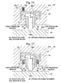
- the springs 33 were provided between the head section bottom surface U of the leaf seal ring 26 and the opposing wall surface U' of the stator blade 24a facing the head section bottom surface U, they may be provided between the head section upper surface V of the leaf seal ring 26 and the opposing inner peripheral surface of the concave section 31, as in the sixth embodiment shown in FIG. 16. They may also be provided between the head section bottom surface W of the leaf seal ring 26 on the low-pressure-region and the opposing inner peripheral surface of the concave section 31 facing the head section bottom surface W in the low-pressure-region. Also, the springs 33 may be served by leaf springs 36.
- the location of the springs 33 across the boundary formed by the planar plates 28 is not limited to either the high-pressure-region or the low-pressure-region, such that, as shown in FIG. 17, they may be provided on both high- and low-pressure-regions.
- the leaf seal ring 26 can be floated stably towards the outer peripheral side of the rotation shaft 23, during the lowspeed operation of the rotation shaft 23, it is possible to reliably prevent the tips 28 of the planar plate 28 to contact the peripheral surface 23a of the rotation shaft 23. Also, compared with the case of providing the springs only on one side of the planar plates 33, the load exerted by the leaf seal ring 26 on the springs 33 is reduced to a half so that degradation caused by the load on the springs 33 by the leaf seal ring 26 can be controlled.
- the pushing member may be attached to the stator blade 24a side using the holding section 38.
- the holding section 38 having the pushing member simply by attaching the holding section 38 having the pushing member.
- a pushing member is deteriorated or damaged, only the holding member 38 holding the relevant pushing member needs to be detached so that maintenance of pushing member can be performed efficiently.
- the pushing member may be provided on the leaf seal ring 26 side.
- pushing members may be provided between the stator blade 24a and the leaf seal ring 26, without specially fabricating the concave section 31 of the stator blade 24a.
- the leaf springs 36 are provided on the leaf seal ring 26 side, thereby permitting simpler detachment compared with the case of attachment to the stator blade 24a, if a pushing member is deteriorated or damaged, work of maintaining the pushing member is facilitated.
- pushing members are not limited to springs 33 or leaf springs 36, so that the pushing members may be served by any means by which, when the differential sealing pressure is low, the leaf seal ring 26 is pushed towards the outer radial direction, and when the differential sealing pressure is high, the pushing force is absorbed by the pressure of the combustion gas guided into the space between the leaf seal ring 26 and the stator blade 24a.
Landscapes
- Engineering & Computer Science (AREA)
- General Engineering & Computer Science (AREA)
- Mechanical Engineering (AREA)
- Turbine Rotor Nozzle Sealing (AREA)
- Sealing Devices (AREA)
- Sealing Using Fluids, Sealing Without Contact, And Removal Of Oil (AREA)
Applications Claiming Priority (2)
| Application Number | Priority Date | Filing Date | Title |
|---|---|---|---|
| JP2001298748A JP3702212B2 (ja) | 2001-09-28 | 2001-09-28 | 軸シール機構及びタービン |
| JP2001298748 | 2001-09-28 |
Publications (3)
| Publication Number | Publication Date |
|---|---|
| EP1298366A2 true EP1298366A2 (fr) | 2003-04-02 |
| EP1298366A3 EP1298366A3 (fr) | 2004-01-21 |
| EP1298366B1 EP1298366B1 (fr) | 2005-12-14 |
Family
ID=19119599
Family Applications (1)
| Application Number | Title | Priority Date | Filing Date |
|---|---|---|---|
| EP02021351A Expired - Lifetime EP1298366B1 (fr) | 2001-09-28 | 2002-09-23 | Joint pour arbre tournant et turbine |
Country Status (6)
| Country | Link |
|---|---|
| US (1) | US6976680B2 (fr) |
| EP (1) | EP1298366B1 (fr) |
| JP (1) | JP3702212B2 (fr) |
| CN (1) | CN1282841C (fr) |
| CA (1) | CA2404453C (fr) |
| DE (1) | DE60207955T2 (fr) |
Cited By (5)
| Publication number | Priority date | Publication date | Assignee | Title |
|---|---|---|---|---|
| EP1479952A2 (fr) * | 2003-05-21 | 2004-11-24 | Mitsubishi Heavy Industries, Ltd. | Dispositif d'étanchéité pour axe |
| GB2411931A (en) * | 2004-03-08 | 2005-09-14 | Alstom Technology Ltd | A leaf seal arrangement |
| EP1760270A2 (fr) * | 2005-09-02 | 2007-03-07 | General Electric Company | Agencement d'étanchéité |
| EP2397728A3 (fr) * | 2003-05-21 | 2012-04-18 | Mitsubishi Heavy Industries, Ltd. | Mécanisme de joint pour arbre et machine pour fluide de grande taille |
| EP2631433A1 (fr) * | 2012-02-27 | 2013-08-28 | Siemens Aktiengesellschaft | Dispositif d'étanchéité axialement déplaçable d'une turbomachine |
Families Citing this family (32)
| Publication number | Priority date | Publication date | Assignee | Title |
|---|---|---|---|---|
| US7066470B2 (en) * | 2001-12-05 | 2006-06-27 | General Electric Company | Active seal assembly |
| US20040155977A1 (en) * | 2003-02-07 | 2004-08-12 | Clark Airell R. | Digital camera that enters a sub-sampling mode for at least one auto function |
| CN101044345B (zh) * | 2004-10-22 | 2012-03-21 | 伯克哈特压缩机股份公司 | 活塞杆密封装置、密封活塞杆的方法及包括密封装置的压缩机 |
| JP3970298B2 (ja) * | 2005-11-10 | 2007-09-05 | 三菱重工業株式会社 | 軸シール機構 |
| US8382119B2 (en) | 2006-08-15 | 2013-02-26 | General Electric Company | Compliant plate seals for turbomachinery |
| US7419164B2 (en) * | 2006-08-15 | 2008-09-02 | General Electric Company | Compliant plate seals for turbomachinery |
| US20080048398A1 (en) * | 2006-08-24 | 2008-02-28 | United Technologies Corporation | Gap sealing arrangement |
| US7703774B2 (en) * | 2006-09-12 | 2010-04-27 | General Electric Company | Shaft seal using shingle members |
| US20080107525A1 (en) * | 2006-11-02 | 2008-05-08 | General Electric Company | Shaft seal formed of tapered compliant plate members |
| US7744092B2 (en) * | 2007-04-30 | 2010-06-29 | General Electric Company | Methods and apparatus to facilitate sealing in rotary machines |
| US8205889B2 (en) * | 2007-11-27 | 2012-06-26 | General Electric Company | Methods and apparatus to facilitate sealing in rotary machines |
| US7909335B2 (en) * | 2008-02-04 | 2011-03-22 | General Electric Company | Retractable compliant plate seals |
| US20100143102A1 (en) * | 2008-02-18 | 2010-06-10 | General Electric Company | Compliant plate seal with self-correcting behavior |
| DE102009015122A1 (de) * | 2009-03-31 | 2010-10-14 | Alstom Technology Ltd. | Lamellendichtung für eine Strömungsmaschine |
| US8333544B1 (en) | 2009-08-14 | 2012-12-18 | Florida Turbine Technologies, Inc. | Card seal for a turbomachine |
| US8152462B1 (en) | 2009-08-19 | 2012-04-10 | Florida Turbine Technologies, Inc. | Card seal with conical flexible seal |
| US8690158B2 (en) | 2010-07-08 | 2014-04-08 | Siemens Energy, Inc. | Axially angled annular seals |
| US9206904B2 (en) | 2010-07-08 | 2015-12-08 | Siemens Energy, Inc. | Seal including flexible seal strips |
| US8777563B2 (en) * | 2011-01-31 | 2014-07-15 | General Electric Company | Axial brush seal |
| US8454023B2 (en) * | 2011-05-10 | 2013-06-04 | General Electric Company | Retractable seal system |
| US8932001B2 (en) * | 2011-09-06 | 2015-01-13 | General Electric Company | Systems, methods, and apparatus for a labyrinth seal |
| JP5999919B2 (ja) | 2012-02-17 | 2016-09-28 | 三菱日立パワーシステムズ株式会社 | 単車室型蒸気タービンおよび一軸型コンバインドサイクル発電装置 |
| JP5851890B2 (ja) * | 2012-03-08 | 2016-02-03 | 三菱重工業株式会社 | 軸シール装置 |
| US9540942B2 (en) * | 2012-04-13 | 2017-01-10 | General Electric Company | Shaft sealing system for steam turbines |
| JP6012505B2 (ja) * | 2013-02-22 | 2016-10-25 | 三菱重工業株式会社 | 軸シール装置及び回転機械 |
| JP5848372B2 (ja) * | 2014-01-28 | 2016-01-27 | 三菱重工業株式会社 | 軸シール装置及び回転機械 |
| JP6168706B2 (ja) * | 2014-12-16 | 2017-07-26 | 三菱日立パワーシステムズ株式会社 | 軸シール機構 |
| JP6270053B2 (ja) * | 2014-12-16 | 2018-01-31 | 三菱日立パワーシステムズ株式会社 | 軸シール機構 |
| JP6245762B2 (ja) * | 2014-12-16 | 2017-12-13 | 三菱日立パワーシステムズ株式会社 | 軸シール機構 |
| JP6631837B2 (ja) * | 2016-05-09 | 2020-01-15 | 三菱日立パワーシステムズ株式会社 | シールセグメント及び回転機械 |
| CN113410591B (zh) * | 2021-06-03 | 2022-05-20 | 立讯精密工业(滁州)有限公司 | 一种射频器件 |
| IT202200006518A1 (it) * | 2022-04-01 | 2023-10-01 | Nuovo Pignone Tecnologie Srl | Sistema di tenuta con protezione contro le sovrappressioni, macchina e metodo |
Family Cites Families (18)
| Publication number | Priority date | Publication date | Assignee | Title |
|---|---|---|---|---|
| US1855890A (en) * | 1929-10-12 | 1932-04-26 | Gen Electric | Spring retainer for shaft packings and the like |
| US2600991A (en) * | 1949-06-14 | 1952-06-17 | Gen Electric | Labyrinth seal arrangement |
| GB1224234A (en) * | 1968-07-19 | 1971-03-03 | English Electric Co Ltd | Turbines |
| CH582319A5 (fr) | 1975-03-05 | 1976-11-30 | Bbc Brown Boveri & Cie | |
| JPS61152906A (ja) * | 1984-12-27 | 1986-07-11 | Toshiba Corp | タ−ビンのシ−ル部隙間調整装置 |
| US5002288A (en) | 1988-10-13 | 1991-03-26 | General Electric Company | Positive variable clearance labyrinth seal |
| GB8907695D0 (en) * | 1989-04-05 | 1989-05-17 | Cross Mfg Co | Seals |
| US5112761A (en) * | 1990-01-10 | 1992-05-12 | Microunity Systems Engineering | Bicmos process utilizing planarization technique |
| US5603510A (en) * | 1991-06-13 | 1997-02-18 | Sanders; William P. | Variable clearance seal assembly |
| US5395124A (en) * | 1993-01-04 | 1995-03-07 | Imo Industries, Inc. | Retractible segmented packing ring for fluid turbines having gravity springs to neutralize packing segment weight forces |
| JP3776481B2 (ja) | 1995-07-10 | 2006-05-17 | 三菱重工業株式会社 | 回転体のシール装置 |
| US6027121A (en) * | 1997-10-23 | 2000-02-22 | General Electric Co. | Combined brush/labyrinth seal for rotary machines |
| GB9801864D0 (en) * | 1998-01-30 | 1998-03-25 | Rolls Royce Plc | A seal arrangement |
| CA2303151C (fr) * | 1998-07-13 | 2004-08-31 | Mitsubishi Heavy Industries, Ltd. | Joint d'arbre et turbine utilisant ce joint |
| JP2000120879A (ja) | 1998-10-20 | 2000-04-28 | Mitsubishi Heavy Ind Ltd | ターボ回転機械の自動調整シール |
| US6250641B1 (en) * | 1998-11-25 | 2001-06-26 | General Electric Co. | Positive biased packing ring brush seal combination |
| US6331006B1 (en) * | 2000-01-25 | 2001-12-18 | General Electric Company | Brush seal mounting in supporting groove using flat spring with bifurcated end |
| US6527115B2 (en) * | 2001-02-02 | 2003-03-04 | Omnisonics Medical Technologies, Inc. | Dispensation and disposal container for medical devices |
-
2001
- 2001-09-28 JP JP2001298748A patent/JP3702212B2/ja not_active Expired - Lifetime
-
2002
- 2002-09-20 CA CA002404453A patent/CA2404453C/fr not_active Expired - Lifetime
- 2002-09-23 EP EP02021351A patent/EP1298366B1/fr not_active Expired - Lifetime
- 2002-09-23 DE DE60207955T patent/DE60207955T2/de not_active Expired - Lifetime
- 2002-09-24 CN CNB021434085A patent/CN1282841C/zh not_active Expired - Lifetime
- 2002-09-25 US US10/253,511 patent/US6976680B2/en not_active Expired - Lifetime
Non-Patent Citations (1)
| Title |
|---|
| None |
Cited By (10)
| Publication number | Priority date | Publication date | Assignee | Title |
|---|---|---|---|---|
| EP1479952A2 (fr) * | 2003-05-21 | 2004-11-24 | Mitsubishi Heavy Industries, Ltd. | Dispositif d'étanchéité pour axe |
| EP1479952A3 (fr) * | 2003-05-21 | 2004-12-01 | Mitsubishi Heavy Industries, Ltd. | Dispositif d'étanchéité pour axe |
| CN1324221C (zh) * | 2003-05-21 | 2007-07-04 | 三菱重工业株式会社 | 轴密封机构 |
| US7364165B2 (en) | 2003-05-21 | 2008-04-29 | Mitsubishi Heavy Industries, Ltd. | Shaft seal mechanism |
| EP2397728A3 (fr) * | 2003-05-21 | 2012-04-18 | Mitsubishi Heavy Industries, Ltd. | Mécanisme de joint pour arbre et machine pour fluide de grande taille |
| GB2411931A (en) * | 2004-03-08 | 2005-09-14 | Alstom Technology Ltd | A leaf seal arrangement |
| EP1760270A2 (fr) * | 2005-09-02 | 2007-03-07 | General Electric Company | Agencement d'étanchéité |
| EP1760270A3 (fr) * | 2005-09-02 | 2010-05-05 | General Electric Company | Agencement d'étanchéité |
| EP2631433A1 (fr) * | 2012-02-27 | 2013-08-28 | Siemens Aktiengesellschaft | Dispositif d'étanchéité axialement déplaçable d'une turbomachine |
| WO2013127687A1 (fr) * | 2012-02-27 | 2013-09-06 | Siemens Aktiengesellschaft | Dispositif d'étanchéité axialement mobile d'une turbomachine |
Also Published As
| Publication number | Publication date |
|---|---|
| US6976680B2 (en) | 2005-12-20 |
| EP1298366B1 (fr) | 2005-12-14 |
| CN1410691A (zh) | 2003-04-16 |
| US20030062686A1 (en) | 2003-04-03 |
| DE60207955D1 (de) | 2006-01-19 |
| EP1298366A3 (fr) | 2004-01-21 |
| JP2003106105A (ja) | 2003-04-09 |
| CA2404453C (fr) | 2006-09-12 |
| JP3702212B2 (ja) | 2005-10-05 |
| DE60207955T2 (de) | 2006-08-31 |
| CN1282841C (zh) | 2006-11-01 |
| CA2404453A1 (fr) | 2003-03-28 |
Similar Documents
| Publication | Publication Date | Title |
|---|---|---|
| US6976680B2 (en) | Shaft seal structure and turbine | |
| EP1626210B1 (fr) | Dispositif d'étanchéité pour axe | |
| US6786488B2 (en) | Seal structure, turbine having the same, and leak-preventing seal system for rotating shaft | |
| RU2501955C2 (ru) | Конструкция уплотнения для уплотнения пространства между вращающимся элементом и неподвижным элементом (варианты) | |
| CN100396885C (zh) | 轴密封机构、轴密封机构的组装结构和大型流体机械 | |
| RU2522722C2 (ru) | Уплотнительный узел и паровая турбина, содержащая уплотнительный узел | |
| JP4212156B2 (ja) | 可撓性布シール・アセンブリ | |
| US6719296B2 (en) | Seal for a rotating member | |
| EP0578377A1 (fr) | Joint d'étanchéité | |
| WO2010146805A1 (fr) | Joint d'arbre et machine rotative pourvue de ce dernier | |
| JP2002013647A (ja) | 軸シール機構及びガスタービン | |
| US20170114655A1 (en) | Sealing assembly | |
| JP5848372B2 (ja) | 軸シール装置及び回転機械 | |
| JP2001355737A (ja) | 表面追従ブラシシール | |
| EP3249172B1 (fr) | Dispositif d'étanchéité pour turbine, turbine, et plaque mince pour dispositif d'étanchéité | |
| CN110735795A (zh) | 一种罗茨鼓风机转子端面环形密封结构 | |
| JP2005002995A (ja) | 軸シール機構、軸シール機構の組み付け構造、及び大型流体機械 | |
| EP3492705A1 (fr) | Système d'étanchéité à film fluide | |
| JP4031699B2 (ja) | 軸シール機構及びタービン | |
| KR20090040956A (ko) | 가스터빈용 베어링 시일 | |
| JPH1181911A (ja) | 軸流式タービンの静翼におけるシール装置 | |
| CN210195825U (zh) | 一种端柱面结合的双作用柔性支承干气密封装置 | |
| CN112983564A (zh) | 一种汽轮机汽压随动开闭式轴向减压汽封结构 | |
| JP4643228B2 (ja) | 軸シール | |
| JP3917997B2 (ja) | 軸シール機構 |
Legal Events
| Date | Code | Title | Description |
|---|---|---|---|
| PUAI | Public reference made under article 153(3) epc to a published international application that has entered the european phase |
Free format text: ORIGINAL CODE: 0009012 |
|
| 17P | Request for examination filed |
Effective date: 20020923 |
|
| AK | Designated contracting states |
Kind code of ref document: A2 Designated state(s): AT BE BG CH CY CZ DE DK EE ES FI FR GB GR IE IT LI LU MC NL PT SE SK TR Designated state(s): AT BE BG CH CY CZ DE DK EE ES FI FR GB GR IE IT LI LU MC NL PT SE SK TR |
|
| AX | Request for extension of the european patent |
Extension state: AL LT LV MK RO SI |
|
| PUAL | Search report despatched |
Free format text: ORIGINAL CODE: 0009013 |
|
| AK | Designated contracting states |
Kind code of ref document: A3 Designated state(s): AT BE BG CH CY CZ DE DK EE ES FI FR GB GR IE IT LI LU MC NL PT SE SK TR |
|
| AX | Request for extension of the european patent |
Extension state: AL LT LV MK RO SI |
|
| 17Q | First examination report despatched |
Effective date: 20040419 |
|
| AKX | Designation fees paid |
Designated state(s): CH DE FR GB IT LI |
|
| GRAP | Despatch of communication of intention to grant a patent |
Free format text: ORIGINAL CODE: EPIDOSNIGR1 |
|
| GRAS | Grant fee paid |
Free format text: ORIGINAL CODE: EPIDOSNIGR3 |
|
| GRAA | (expected) grant |
Free format text: ORIGINAL CODE: 0009210 |
|
| AK | Designated contracting states |
Kind code of ref document: B1 Designated state(s): CH DE FR GB IT LI |
|
| REG | Reference to a national code |
Ref country code: GB Ref legal event code: FG4D |
|
| REG | Reference to a national code |
Ref country code: CH Ref legal event code: EP |
|
| REF | Corresponds to: |
Ref document number: 60207955 Country of ref document: DE Date of ref document: 20060119 Kind code of ref document: P |
|
| REG | Reference to a national code |
Ref country code: CH Ref legal event code: NV Representative=s name: E. BLUM & CO. PATENTANWAELTE |
|
| ET | Fr: translation filed | ||
| PLBE | No opposition filed within time limit |
Free format text: ORIGINAL CODE: 0009261 |
|
| STAA | Information on the status of an ep patent application or granted ep patent |
Free format text: STATUS: NO OPPOSITION FILED WITHIN TIME LIMIT |
|
| 26N | No opposition filed |
Effective date: 20060915 |
|
| REG | Reference to a national code |
Ref country code: CH Ref legal event code: PFA Owner name: MITSUBISHI HEAVY INDUSTRIES, LTD. Free format text: MITSUBISHI HEAVY INDUSTRIES, LTD.#5-1, MARUNOUCHI 1-CHOME, CHIYODA-KU#TOKYO (JP) -TRANSFER TO- MITSUBISHI HEAVY INDUSTRIES, LTD.#5-1, MARUNOUCHI 1-CHOME, CHIYODA-KU#TOKYO (JP) |
|
| REG | Reference to a national code |
Ref country code: FR Ref legal event code: PLFP Year of fee payment: 15 |
|
| REG | Reference to a national code |
Ref country code: FR Ref legal event code: PLFP Year of fee payment: 16 |
|
| REG | Reference to a national code |
Ref country code: FR Ref legal event code: PLFP Year of fee payment: 17 |
|
| PGFP | Annual fee paid to national office [announced via postgrant information from national office to epo] |
Ref country code: IT Payment date: 20210811 Year of fee payment: 20 Ref country code: FR Payment date: 20210812 Year of fee payment: 20 Ref country code: CH Payment date: 20210916 Year of fee payment: 20 |
|
| PGFP | Annual fee paid to national office [announced via postgrant information from national office to epo] |
Ref country code: GB Payment date: 20210818 Year of fee payment: 20 Ref country code: DE Payment date: 20210810 Year of fee payment: 20 |
|
| REG | Reference to a national code |
Ref country code: DE Ref legal event code: R071 Ref document number: 60207955 Country of ref document: DE |
|
| REG | Reference to a national code |
Ref country code: CH Ref legal event code: PL |
|
| REG | Reference to a national code |
Ref country code: GB Ref legal event code: PE20 Expiry date: 20220922 |
|
| PG25 | Lapsed in a contracting state [announced via postgrant information from national office to epo] |
Ref country code: GB Free format text: LAPSE BECAUSE OF EXPIRATION OF PROTECTION Effective date: 20220922 |