EP1296419A2 - Leistungsversorgungsausschalteinrichtung für Fahrzeug - Google Patents
Leistungsversorgungsausschalteinrichtung für Fahrzeug Download PDFInfo
- Publication number
- EP1296419A2 EP1296419A2 EP02021259A EP02021259A EP1296419A2 EP 1296419 A2 EP1296419 A2 EP 1296419A2 EP 02021259 A EP02021259 A EP 02021259A EP 02021259 A EP02021259 A EP 02021259A EP 1296419 A2 EP1296419 A2 EP 1296419A2
- Authority
- EP
- European Patent Office
- Prior art keywords
- power supply
- connector connecting
- electric component
- connecting portion
- component circuit
- Prior art date
- Legal status (The legal status is an assumption and is not a legal conclusion. Google has not performed a legal analysis and makes no representation as to the accuracy of the status listed.)
- Withdrawn
Links
Images


Classifications
-
- H—ELECTRICITY
- H02—GENERATION; CONVERSION OR DISTRIBUTION OF ELECTRIC POWER
- H02H—EMERGENCY PROTECTIVE CIRCUIT ARRANGEMENTS
- H02H3/00—Emergency protective circuit arrangements for automatic disconnection directly responsive to an undesired change from normal electric working condition with or without subsequent reconnection ; integrated protection
- H02H3/12—Emergency protective circuit arrangements for automatic disconnection directly responsive to an undesired change from normal electric working condition with or without subsequent reconnection ; integrated protection responsive to underload or no-load
-
- B—PERFORMING OPERATIONS; TRANSPORTING
- B60—VEHICLES IN GENERAL
- B60R—VEHICLES, VEHICLE FITTINGS, OR VEHICLE PARTS, NOT OTHERWISE PROVIDED FOR
- B60R16/00—Electric or fluid circuits specially adapted for vehicles and not otherwise provided for; Arrangement of elements of electric or fluid circuits specially adapted for vehicles and not otherwise provided for
- B60R16/02—Electric or fluid circuits specially adapted for vehicles and not otherwise provided for; Arrangement of elements of electric or fluid circuits specially adapted for vehicles and not otherwise provided for electric constitutive elements
- B60R16/03—Electric or fluid circuits specially adapted for vehicles and not otherwise provided for; Arrangement of elements of electric or fluid circuits specially adapted for vehicles and not otherwise provided for electric constitutive elements for supply of electrical power to vehicle subsystems or for
-
- H—ELECTRICITY
- H01—ELECTRIC ELEMENTS
- H01R—ELECTRICALLY-CONDUCTIVE CONNECTIONS; STRUCTURAL ASSOCIATIONS OF A PLURALITY OF MUTUALLY-INSULATED ELECTRICAL CONNECTING ELEMENTS; COUPLING DEVICES; CURRENT COLLECTORS
- H01R13/00—Details of coupling devices of the kinds covered by groups H01R12/70 or H01R24/00 - H01R33/00
- H01R13/66—Structural association with built-in electrical component
- H01R13/70—Structural association with built-in electrical component with built-in switch
-
- H—ELECTRICITY
- H02—GENERATION; CONVERSION OR DISTRIBUTION OF ELECTRIC POWER
- H02H—EMERGENCY PROTECTIVE CIRCUIT ARRANGEMENTS
- H02H11/00—Emergency protective circuit arrangements for preventing the switching-on in case an undesired electric working condition might result
-
- H—ELECTRICITY
- H02—GENERATION; CONVERSION OR DISTRIBUTION OF ELECTRIC POWER
- H02J—ELECTRIC POWER NETWORKS; CIRCUIT ARRANGEMENTS OR SYSTEMS FOR SUPPLYING OR DISTRIBUTING ELECTRIC POWER; SYSTEMS FOR STORING ELECTRIC ENERGY
- H02J2105/00—Networks for supplying or distributing electric power characterised by their spatial reach or by the load
- H02J2105/30—Networks for supplying or distributing electric power characterised by their spatial reach or by the load the load networks being external to vehicles, i.e. exchanging power with vehicles
- H02J2105/33—Networks for supplying or distributing electric power characterised by their spatial reach or by the load the load networks being external to vehicles, i.e. exchanging power with vehicles exchanging power with road vehicles
-
- H—ELECTRICITY
- H02—GENERATION; CONVERSION OR DISTRIBUTION OF ELECTRIC POWER
- H02J—ELECTRIC POWER NETWORKS; CIRCUIT ARRANGEMENTS OR SYSTEMS FOR SUPPLYING OR DISTRIBUTING ELECTRIC POWER; SYSTEMS FOR STORING ELECTRIC ENERGY
- H02J7/00—Circuit arrangements for charging or discharging batteries or for supplying loads from batteries
- H02J7/60—Circuit arrangements for charging or discharging batteries or for supplying loads from batteries including safety or protection arrangements
- H02J7/62—Circuit arrangements for charging or discharging batteries or for supplying loads from batteries including safety or protection arrangements against overcurrent
Definitions
- the present invention relates to a power supply cut system for a vehicle, which cuts power during disconnection of a connector.
- a vehicular electric component circuit 50 mainly includes a power supply 51 for supplying a predetermined power supply voltage, a fuse 52 for preventing conduction of an overcurrent, a switch 53 for driving an electric component load 54, and the electric component load 54 operated by a power supply voltage.
- a connector connecting portion 55 is provided as a main circuit component in a suitable place of the vehicular electric component circuit 50. That is, wiring between the power supply 51 and the electric component load 54 is carried out by wire harnesses, and connection between the wire harnesses is carried out by connector connection, which are most convenient in a vehicle line assembly, services and the like.
- the power supply 51 for an automobile is set at a low voltage of L4V, and almost no arc discharge occurs even if an inserting and pulling-out operation of the connector connecting portion 55 is carried out in a state of low-voltage application.
- a power supply cut system for a vehicle is not necessary, and none has been mounted.
- the present invention was made to solve the above-described problems, and an object of the present invention is to provide a power supply cut system for a vehicle capable of preventing occurrence of the arc discharge and an electric shock in handling of a connector connecting portion.
- a power supply cut system for a vehicle which comprises power supply cutting means including a power supply cutting portion provided in a vehicular electric component circuit on an upper stream than a connector connecting portion toward a power supply to make the vehicular electric component circuit non-conductive, and power supply cut means composed of a control unit for controlling the power supply cutting portion, and cut signal inputting means for entering a power supply cut signal to the control unit in a connected or disconnected state of the connector connecting portion.
- the power supply cut signal is entered to the control unit by the cut signal inputting means.
- the control unit controls the power supply cutting portion to make the vehicular electric component circuit non-conductive.
- the power supply cut signal is entered to the control unit by the cut signal inputting means, and the vehicular electric component circuit is made non-conductive by the power supply cutting means.
- the connector connecting portion includes a locking portion, and lock detecting means provided to detect a locked or lock released state of the locking portion and, when the lock detecting means detects the lock released state, the power supply cutting means makes the vehicular electric component circuit non-conductive.
- the vehicular electric component circuit is made non-conductive by the power supply cutting means, and no power supply voltages are applied to the connector connecting portion. In this state, a separating operation of the connector connecting portion is completely carried out.
- a fitting operation of the connector connecting portion is carried out to fit the separated connector connecting portion, and the locking portion is locked, the vehicular electric component circuit is recovered to the conductive state by the power supply cutting means, and the power supply voltage is applied to the connector connecting portion.
- a plurality of connector connecting purtions are provided, and at least one of the plurality of connector connecting portions includes the lock detecting means.
- the power supply cutting means makes the vehicular electric component circuit non-conductive on the upper stream than the connector connecting portion toward the power supply, and cuts off power supply to the other connector connecting portions.
- At least one of the plurality of connector connecting portions includes the lock detecting means.
- lock releasing information is outputted from the lock detecting means.
- the control unit controls the power supply cutting portion to make the vehicular electric component circuit non-conductive on the upper stream than the connector connecting portion toward the power supply, and cuts off power supply to the other connector connecting portions. As a result, no power supply voltages are applied to the other connector connecting portions and, in this state, a separating operation of the connector connecting portion is carried out.
- the locking portion of the connector connecting portion having the lock detecting means is locked, locking information is outputted from the lock detecting means.
- the control unit controls the power supply cutting portion to recover the vehicular electric component circuit to the conductive state, and power supply voltages are applied to the other connector connecting portions.
- the cut signal inputting means is a vehicular ignition key switch for entering the power supply cut signal outputted from a power supply cutting position to the control unit.
- the control unit controls the power supply cutting portion to make the vehicular electric component circuit non-conductive, and no power supply voltages are applied to the connector connecting portion. In this state, a separating operation of the connector connecting portion is carried out.
- the control unit controls the power supply cutting portion to recover the vehicular electric component circuit to the conductive state, and the power supply voltage is applied to the connector connecting portion.
- Fig. 2A and Fig. 2B show a vehicular electric component circuit of a power supply cut system for a vehicle according to a first embodiment of the present invention: Fig. 2A a circuit block diagram showing the vehicular electric component circuit in fitting of a connector connecting portion (locking portion is in a locked state); and Fig. 2B a circuit block diagram showing the vehicular electric component circuit in lock releasing of the connector connecting portion.
- a vehicular electric component circuit 1 is mainly composed of a power supply 2 for supplying a predetermined power supply voltuge (42V), a fuse 3 for preventing conduction of an overcurrent, a connector connecting portion 4 for connecting wire harnesses with each other, a switch 5 for driving an electric component load 6, and the electric component load 6 operated by a power supply voltage.
- a power supply 2 for supplying a predetermined power supply voltuge (42V)
- a fuse 3 for preventing conduction of an overcurrent
- a connector connecting portion 4 for connecting wire harnesses with each other
- a switch 5 for driving an electric component load 6 operated by a power supply voltage.
- the connector connecting portion 4 is composed of female and male terminal side connectors 10 and 11.
- the separated connectors 10 and 11 are fitted into each other by an inserting (fitting) operation, and the fitted connectors 10 and 11 are separated from each other by a pulling-away (separating) operation.
- This connector connecting portion 4 includes a locking portion (not shown) provided to lock the fitted connectors. Unless this locking portion is released, the connectors 10 and 11 cannot be separated trom each other.
- the connector connecting portion 4 also includes lock detecting means (cut signal inputting means) 12 provided to detect a locked or lock released state of the locking portion (not shown).
- the lock detecting means 12 includes a detection contact switch turned off in the locked state of the locking portion (not shown), and turned on in the lock released state of the same. When this lock detecting means 12 detects the lock released state, i.e., ON state, the vehicular electric component circuit 1 is made non-conductive by power supply cutting means 13.
- the power supply cutting means 13 includes a control unit (control portion) 14 for monitoring an output of the lock detecting means 12 and controlling a power supply cutting portion 15, and the power supply cutting portion 15 provided in the vehicular electric component circuit 1 on an upper stream than the connector connecting portion 4 toward the power supply to make the vehicular electric component circuit 1 non-conductive.
- the power supply cutting portion 15 includes a relay circuit. With the relay circuit ON, the vehicular electric component circuit 1 is made conductive, and made non-conductive with the relay circuit OFF.
- the lock detecting means 12 detects this, and the control unit 14 controls the power supply cutting portion 15 to an OFF state, making the vehicular electric component circuit 1 non-conductive. No power supply voltages are supplied to the connector connecting portion 4 and, in this state, a separating operation of the connector connecting portion 4 is carried out.
- the lock detecting means 12 detects this, and the control unit 14 controls the power supply cutting portion 15 to an ON state, recovering the vehicular electric component circuit 1 to the conductive state. Accordingly, a power supply voltage can be supplied from the power supply 2 to the electric component load 6.
- the power supply cutting means 13 is composed of the control unit 14 and the power supply cutting portion 15.
- any type of power supply cutting means can be used as long as it can make the vehicular electric component circuit 1 non-conductive on the upper stream than the connector connecting portion 4 toward the power supply when the lock detecting means 12 of the connector connecting portion 4 detects lock releasing.
- Fig. 3 and Fig. 4 show a vehicular electric component circuit of a power supply cut system for a vehicle according to a second embodiment of the present invention: Fig. 3 a circuit block diagram showing the vehicular electric component circuit in fitting of each of a plurality of connector connecting portions (locking portion is in a locked state); and Fig. 4 a circuit block diagram showing the vehicular electric component circuit in lock releasing of the connector connecting portion.
- a vehicular electric component circuit 21 is mainly composed of a power supply 22 for supplying a predetermined power supply voltage (42V), a fuse 23 for preventing conduction of an overcurrent, a connector connecting portion 24 for connecting wire harnesses with each other, a switch 25 for driving an electric component load 26, and the electric component load 26 operated by a power supply voltage.
- the connector connecting portion 24 is composed of female and male terminal side connectors 27 end 28.
- the separated connectors 27 and 28 are fitted into each other by an inserting (fitting) operation, and the fitted connectors 27 and 28 are separated from each other by a pulling-away (separating) operation.
- This connector connecting portion 24 includes a locking portion (not shown) provided to lock the fitted connectors 27 and 28. Unless this locking portion is released, the connectors 27 and 28 cannot be separated from each other.
- a plurality of connector connecting portion 24 are provided. Fuses 23A, 23B, 23C and 23D are connected to the plurality of connector connecting portions 24A, 24B, 24C and 24D respectively. Also, a plurality of electric component loads, i.e., a room lamp 26A, a head lamp 26B, a small lamp 26C, a cigarette lighter 26D, and the like are connected through switches 25A, 25B, 25C and 25D to the same.
- At least one (connector connecting portion 24A in the embodiment) of the plurality of connector connecting portions 24A, 24B, 24C and 24D includes lock detecting means (cut signal inputting means) 29 provided to detect a locked or lock released state of the locking portion (not shown).
- the lock detecting means 29 includes a detection checking switch turned off in the locked sate of the locking portion (not shown), and turned on in the lock released state of the same. When this lock detecting means 29 detects the lock released state, i.e., ON state, the vehicular electric component circuit 21 is made non-conductive by power supply cutting means 30.
- the power supply cutting means 30 includes a control unit (control portion) 31 for monitoring an output of the lock detecting means 29 and controlling a power supply cutting portion 32, and the power supply cutting portion 32 provided in the vehicular electric component circuit 21 on an upper stream than the connector connecting portion 24A toward the power supply to make the vehicular electric component circuit 21 non-conductive.
- the power supply cutting portion 32 includes a relay circuit. With the relay circuit ON, the vehicular electric component circuit 21 is made conductive, and made non-conductive with the relay circuit OFF.
- the power supply cutting portion 32 is turned on, making the vehicular electric component circuit 21 conductive. Accordingly, a power supply voltage is supplied from the power supply 22 to the plurality of electric component loads, i.e., the room lamp 26A, the head lamp 26B, the small lamp 26C, the cigarette lighter 26D and the like.
- the lock detecting means 29 detects this, and the control unit 31 controls the power supply cutting portion 32 to an OFF state, making the vehicular electric component circuit 21 non-conductive. No power supply voltages are supplied to the connector connecting portion 24A and the other connector connecting portions 24B, 24c and 24D and, in this state, separating operations ot the connector connecting portions 24A, 24B, 24C and 24D are carried out.
- the lock detecting means 29 detects this, and the control unit 31 controls the power supply cutting portion 32 to an ON state, recovering the vehicular electric component circuit 21 to the conductive state. Accordingly, a power supply voltuge is supplied from the power supply 22 to the electric component loads, i.e., the room lamp 26A, the head lamp 26B, the small lamp 26C, the cigarette lighter 26D and the like.
- the connector connecting portion 24A connected to the room lamp 26A is disconnected to make the vehicular electric component circuit 21 non-conductive, making it possible to prevent occurrence of an arc discharge during replacing of the head lamp 26B. Accordingly, the head lamp 26B can be safely replaced by another.
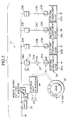
- Fig. 5 and Fig. 6 show a vehicular electric component circuit of a power supply cut system for a vehicle according to a third embodiment of the present invention: Fig. 5 a circuit block diagram showing the vehicular electric component circuit in fitting of each of a plurality of connector connecting portions (locking portion is in a locked state); and Fig. 6 a circuit block diagram showing the vehicular electric component circuit in lock releasing of the connector connecting portion.
- the vehicular electric component circuit 41 is mainly composed of a power supply 22 for supplying a predetermined power supply voltage (42V), a fuse 23 for preventing conduction of an overcurrent, a connector connecting portion 24 for connecting wire harnesses with each other, a switch 25 for driving an electric component load 26, and the electric component load 26 operated by a power supply voltage.
- the connector connecting portion 24 is composed of female and male terminal side connectors 27 and 28.
- the separated connectors 27 and 28 are fitted into each other by an inserting (fitting) operation, and the fitted connectors are separated from each other by a pulling-away (separating) operation.
- a plurality of connector connecting portion 24 are provided. Fuses 23A, 23B, 23C and 23D are connected to the plurality of connector connecting portions 24A, 24B, 24C and 24D. Also, electric component loads 26, i.e., a room lamp 26A, a head lamp 26B, a small lamp 26C, a cigarette lighter 26D, and the like are connected through switches 25A, 25B, 25C and 25D to the same.
- the third embodiment includes power supply cutting means 30 composed of a power supply cutting portion 32 provided in the vehicular electric component circuit 41 on an upper stream than the connector connecting portions 24A, 24B, 24C and 24D toward the power supply to make the vehicular electric component circuit 41 non-conductive, and a control unit (control portion) 31 for controlling the power supply cutting portion 32, and a vehicular ignition switch key (cut signal inputting means) 42 for entering a power supply cut signal to the control unit 31.
- the power supply cutting portion 32 is turned on, making the vehicular electric component circuit 41 conductive. Accordingly, a power supply voltage is supplied from the power supply 22 to the electric component loads 26, i.e., the room lamp 26A, the head lamp 26B, the small lamp 26C, the cigarette lighter 26D and the like.
- a power supply cut signal is entered from the ignition key switch 42 to the control unit 31.
- the control unit 31 controls the puwer supply cutting portion 32 to an OFF state, making the vehicular electric component circuit 41 non-conductive. No power supply voltages are supplied to the connector connecting portions 24A, 24B, 24c and 24D and, in this state, separating operations of the connector connecting portions 24A, 24B, 24C and 24D are carried out.
Landscapes
- Details Of Connecting Devices For Male And Female Coupling (AREA)
Applications Claiming Priority (4)
| Application Number | Priority Date | Filing Date | Title |
|---|---|---|---|
| JP2001289473 | 2001-09-21 | ||
| JP2001289473 | 2001-09-21 | ||
| JP2001397449A JP2003165399A (ja) | 2001-09-21 | 2001-12-27 | 車両用電源カットシステム |
| JP2001397449 | 2001-12-27 |
Publications (2)
| Publication Number | Publication Date |
|---|---|
| EP1296419A2 true EP1296419A2 (de) | 2003-03-26 |
| EP1296419A3 EP1296419A3 (de) | 2004-06-23 |
Family
ID=26622711
Family Applications (1)
| Application Number | Title | Priority Date | Filing Date |
|---|---|---|---|
| EP02021259A Withdrawn EP1296419A3 (de) | 2001-09-21 | 2002-09-19 | Leistungsversorgungsausschalteinrichtung für Fahrzeug |
Country Status (3)
| Country | Link |
|---|---|
| US (1) | US20030057774A1 (de) |
| EP (1) | EP1296419A3 (de) |
| JP (1) | JP2003165399A (de) |
Families Citing this family (2)
| Publication number | Priority date | Publication date | Assignee | Title |
|---|---|---|---|---|
| US20200324719A1 (en) * | 2019-04-09 | 2020-10-15 | Byton North America Corporation | Vehicle isolation switch for low voltage power supplies |
| JP7255576B2 (ja) * | 2020-09-23 | 2023-04-11 | 株式会社デンソーエレクトロニクス | 負荷制御装置 |
Family Cites Families (15)
| Publication number | Priority date | Publication date | Assignee | Title |
|---|---|---|---|---|
| DE1690065A1 (de) * | 1967-09-30 | 1971-04-22 | Siemens Ag | Steckvorrichtung fuer gleisgebundene und gleislose Batteriefahrzeuge |
| US3824403A (en) * | 1972-09-15 | 1974-07-16 | Wagner Electric Corp | Power control circuit for automatic vehicles and the like |
| DE4216812A1 (de) * | 1992-05-21 | 1993-11-25 | Bosch Gmbh Robert | Lösbare elektrische Steckverbindung |
| JPH0620745A (ja) * | 1992-07-06 | 1994-01-28 | Mazda Motor Corp | 車両用給電装置 |
| US5554891A (en) * | 1993-03-30 | 1996-09-10 | Asahi Denso Kabushiki Kaisha | Antitheft device for a vehicle |
| JP3373664B2 (ja) * | 1994-08-05 | 2003-02-04 | マツダ株式会社 | 車両用電源供給装置 |
| US5864106A (en) * | 1997-01-07 | 1999-01-26 | Chrysler Corporation | Battery disconnect switch for electric vehicle |
| JP3314862B2 (ja) * | 1997-02-05 | 2002-08-19 | 住友電装株式会社 | ロック検知コネクタ |
| DE19710416A1 (de) * | 1997-03-13 | 1998-09-17 | Bayerische Motoren Werke Ag | Hochspannungs-Steckverbinder |
| JPH1159291A (ja) * | 1997-08-26 | 1999-03-02 | Harness Sogo Gijutsu Kenkyusho:Kk | 車両における電装品への電力供給装置 |
| DE19823009A1 (de) * | 1998-05-22 | 1999-11-25 | Volkswagen Ag | Vorrichtung zur Ansteuerung elektrischer Verbraucher in einem Kraftfahrzeug |
| JP2000311738A (ja) * | 1999-04-27 | 2000-11-07 | Yazaki Corp | 電気コンタクト |
| DE19958098C2 (de) * | 1999-12-02 | 2003-04-10 | Trw Automotive Electron & Comp | Stromversorgung für Fahrzeuge |
| US6699128B1 (en) * | 2000-10-13 | 2004-03-02 | Igt | Manual lever with locking function for mounting CPU enclosure |
| JP2002234404A (ja) * | 2001-02-09 | 2002-08-20 | Auto Network Gijutsu Kenkyusho:Kk | 自動車内の電力供給システム |
-
2001
- 2001-12-27 JP JP2001397449A patent/JP2003165399A/ja not_active Abandoned
-
2002
- 2002-09-19 EP EP02021259A patent/EP1296419A3/de not_active Withdrawn
- 2002-09-20 US US10/247,635 patent/US20030057774A1/en not_active Abandoned
Also Published As
| Publication number | Publication date |
|---|---|
| US20030057774A1 (en) | 2003-03-27 |
| EP1296419A3 (de) | 2004-06-23 |
| JP2003165399A (ja) | 2003-06-10 |
Similar Documents
| Publication | Publication Date | Title |
|---|---|---|
| US7021950B2 (en) | System and method for preventing electric arcs in connectors feeding power loads and connector used | |
| EP1654793B1 (de) | Leitungsunterbrechungseinrichtung | |
| US5818121A (en) | On-board wiring system for vehicles | |
| CN112644284B (zh) | 汽车电器网络以及用于运行这种汽车电器网络的方法 | |
| KR20010093097A (ko) | 배터리와 안전 차단 기능을 갖는 전기 시스템 | |
| US10343632B2 (en) | Automobile power supply device | |
| US6087737A (en) | Battery disconnection system | |
| JP2000023380A (ja) | 電力供給制御装置 | |
| EP0931701B1 (de) | Trennungssystem für eine Batterie | |
| EP1296419A2 (de) | Leistungsversorgungsausschalteinrichtung für Fahrzeug | |
| CA2150425C (en) | Power supply protection circuit capable of preventing a failure in a mobile satellite communication apparatus resulting from erroneous connection | |
| EP1232913B1 (de) | Einrichtung zur Stromversorgung in einem Kraftfahrzeug | |
| KR20090070078A (ko) | 차폐 케이블을 이용한 고전압 커넥터의 안전장치 | |
| JP3308820B2 (ja) | 車両用電源制御装置 | |
| JPH11329190A (ja) | 車両の異常報知装置 | |
| JP3310876B2 (ja) | 電力供給制御装置 | |
| US7679881B2 (en) | Electrical entity with opening of the load current circuit in an explosion-vulnerable environment | |
| JP2001307834A (ja) | コネクタ及び配線構造 | |
| US20030060068A1 (en) | Connector assembly for vehicle electric equipment circuit | |
| JP2773496B2 (ja) | 電装品のアース装置 | |
| JP2000082371A (ja) | 回路遮断器 | |
| JP2004231047A (ja) | 車載電源システム | |
| EP0885779A2 (de) | Elektromechanische Vorrichtung zur Batterieabschaltung in einem Kraftfahrzeug | |
| JP2001307821A (ja) | コネクタ及び配線構造 | |
| JP2002238135A (ja) | 電源端末装置 |
Legal Events
| Date | Code | Title | Description |
|---|---|---|---|
| PUAI | Public reference made under article 153(3) epc to a published international application that has entered the european phase |
Free format text: ORIGINAL CODE: 0009012 |
|
| 17P | Request for examination filed |
Effective date: 20020919 |
|
| AK | Designated contracting states |
Kind code of ref document: A2 Designated state(s): AT BE BG CH CY CZ DE DK EE ES FI FR GB GR IE IT LI LU MC NL PT SE SK TR Designated state(s): AT BE BG CH CY CZ DE DK EE ES FI FR GB GR IE IT LI LU MC NL PT SE SK TR |
|
| AX | Request for extension of the european patent |
Extension state: AL LT LV MK RO SI |
|
| RIN1 | Information on inventor provided before grant (corrected) |
Inventor name: KUNUGI, MASANORI,C/O YAZAKI PARTS CO., LTD. |
|
| PUAL | Search report despatched |
Free format text: ORIGINAL CODE: 0009013 |
|
| AK | Designated contracting states |
Kind code of ref document: A3 Designated state(s): AT BE BG CH CY CZ DE DK EE ES FI FR GB GR IE IT LI LU MC NL PT SE SK TR |
|
| AX | Request for extension of the european patent |
Extension state: AL LT LV MK RO SI |
|
| RIC1 | Information provided on ipc code assigned before grant |
Ipc: 7B 60R 16/02 B Ipc: 7H 02H 3/12 A |
|
| AKX | Designation fees paid |
Designated state(s): DE FR GB |
|
| STAA | Information on the status of an ep patent application or granted ep patent |
Free format text: STATUS: THE APPLICATION IS DEEMED TO BE WITHDRAWN |
|
| 18D | Application deemed to be withdrawn |
Effective date: 20041224 |