EP0885779A2 - Elektromechanische Vorrichtung zur Batterieabschaltung in einem Kraftfahrzeug - Google Patents
Elektromechanische Vorrichtung zur Batterieabschaltung in einem Kraftfahrzeug Download PDFInfo
- Publication number
- EP0885779A2 EP0885779A2 EP98110595A EP98110595A EP0885779A2 EP 0885779 A2 EP0885779 A2 EP 0885779A2 EP 98110595 A EP98110595 A EP 98110595A EP 98110595 A EP98110595 A EP 98110595A EP 0885779 A2 EP0885779 A2 EP 0885779A2
- Authority
- EP
- European Patent Office
- Prior art keywords
- contact
- motor vehicle
- battery
- coupling rod
- circuit
- Prior art date
- Legal status (The legal status is an assumption and is not a legal conclusion. Google has not performed a legal analysis and makes no representation as to the accuracy of the status listed.)
- Withdrawn
Links
- 230000008878 coupling Effects 0.000 claims description 20
- 238000010168 coupling process Methods 0.000 claims description 20
- 238000005859 coupling reaction Methods 0.000 claims description 20
- 230000005662 electromechanics Effects 0.000 claims description 6
- 230000002035 prolonged effect Effects 0.000 abstract description 3
- 238000010586 diagram Methods 0.000 description 3
- RYGMFSIKBFXOCR-UHFFFAOYSA-N Copper Chemical compound [Cu] RYGMFSIKBFXOCR-UHFFFAOYSA-N 0.000 description 1
- 229910052802 copper Inorganic materials 0.000 description 1
- 239000010949 copper Substances 0.000 description 1
- 238000007599 discharging Methods 0.000 description 1
Images


Classifications
-
- B—PERFORMING OPERATIONS; TRANSPORTING
- B60—VEHICLES IN GENERAL
- B60K—ARRANGEMENT OR MOUNTING OF PROPULSION UNITS OR OF TRANSMISSIONS IN VEHICLES; ARRANGEMENT OR MOUNTING OF PLURAL DIVERSE PRIME-MOVERS IN VEHICLES; AUXILIARY DRIVES FOR VEHICLES; INSTRUMENTATION OR DASHBOARDS FOR VEHICLES; ARRANGEMENTS IN CONNECTION WITH COOLING, AIR INTAKE, GAS EXHAUST OR FUEL SUPPLY OF PROPULSION UNITS IN VEHICLES
- B60K28/00—Safety devices for propulsion-unit control, specially adapted for, or arranged in, vehicles, e.g. preventing fuel supply or ignition in the event of potentially dangerous conditions
- B60K28/10—Safety devices for propulsion-unit control, specially adapted for, or arranged in, vehicles, e.g. preventing fuel supply or ignition in the event of potentially dangerous conditions responsive to conditions relating to the vehicle
- B60K28/14—Safety devices for propulsion-unit control, specially adapted for, or arranged in, vehicles, e.g. preventing fuel supply or ignition in the event of potentially dangerous conditions responsive to conditions relating to the vehicle responsive to accident or emergency, e.g. deceleration, tilt of vehicle
-
- B—PERFORMING OPERATIONS; TRANSPORTING
- B60—VEHICLES IN GENERAL
- B60R—VEHICLES, VEHICLE FITTINGS, OR VEHICLE PARTS, NOT OTHERWISE PROVIDED FOR
- B60R16/00—Electric or fluid circuits specially adapted for vehicles and not otherwise provided for; Arrangement of elements of electric or fluid circuits specially adapted for vehicles and not otherwise provided for
- B60R16/02—Electric or fluid circuits specially adapted for vehicles and not otherwise provided for; Arrangement of elements of electric or fluid circuits specially adapted for vehicles and not otherwise provided for electric constitutive elements
- B60R16/03—Electric or fluid circuits specially adapted for vehicles and not otherwise provided for; Arrangement of elements of electric or fluid circuits specially adapted for vehicles and not otherwise provided for electric constitutive elements for supply of electrical power to vehicle subsystems or for
Definitions
- the present invention relates to an improved electromechanic device for sectioning the battery of a motor vehicle.
- the invention relates to such a device which can be applied to batteries of motor vehicles, such as cars, lorries, trucks and the like.
- the aim of the present invention is to provide an electromechanic device adapted to automatically switch off the current of the main electric system of the motor vehicle in the case of an accident, while holding the safety electric services or the emergency services on the motor vehicle in an operating condition.
- a main object of the present invention is to provide such a device allowing to section off, by a manual operation, the overall electric system of the motor vehicle, while preserving the motor vehicle battery in a full operating charged condition upon prolonged standby periods.
- the above mentioned aim and objects are achieved by the inventive electromechanic device for sectioning the power supply lines coming from the battery of a motor vehicle, characterized in that said device comprises at least a first contact, adapted to close a first portion of the electric circuit power supplying the main electric system of said motor vehicle, and a second contact, adapted to close a second circuit portion power supplying privileged loads of said motor vehicle, said device further comprising means for opening said first contact, in order to exclusively select said privileged loads.
- said contacts are coupled to a rod including means for separating said contacts from their respective power supply circuit portions.
- Said rod moreover, can be axially driven by a plurality of springs, and is held in a position allowing the closure of both the circuit portions by a groove, formed in said rod, in which an end portion of the movable core of an electromagnet is engaged, and by a recess, in which an end portion of a first manually operated switch is engaged.
- said end portion of said movable core is disengaged from said groove by an inertial switch which, upon an accidental impact, would allow the electromagnet to be energized to actuate said movable core to allow said rod to be partially driven as well as said first contact to be removed from said first circuit portion.
- the driving of the rod will be interrupted by a portion of said recess engaging with an end of a first manually operated switch.
- said first switch can be driven in order to disengage the ends thereof to allow said rod to be further driven for disengaging the second contact from the second circuit portion.
- said first switch can be used for manually sectioning the overall circuit.
- a manually operated second switch for partially or fully closing the circuit is moreover provided.
- the device according to the invention provides at first the advantage that it allows the main electric system of the motor vehicle to be automatically switched off, with a consequent reduction of possible fire dangers deriving from a continuously energized or power supplied electric system.
- the provision of the two manually operated switches allows the user to fully switch-off the circuit, as the battery charge must be preserved, or to manually re-energize it again.
- the device according to the invention can be suitably assembled on the motor vehicle battery itself.
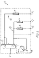
- Figure 1 illustrates an electric diagram of the electromechanic device according to the invention, which is provided for being directly assembled on the motor vehicle battery and being coupled to the positive post of said battery by the clamp 2.
- Figure 1 clearly shows that the circuit, generally indicated by the reference number 1, is in turn subdivided into a first circuit portion 15 and a second circuit portion 16.
- the first circuit portion 15 power supplies the main electric system of the motor vehicle
- the second circuit portion 16 power supplies the so-called "privileged" loads of the motor vehicle, such as the emergency lamps, the inner lamps or lights, the motor vehicle door locking devices or elements, and so on.
- the circuit 1 is moreover provided with a first contact 3 and a second contact 4 coupled by a coupling rod 60 driven by a system of springs, generally indicated by the reference number 10, and which will be disclosed in a more detailed manner hereinafter.
- an electromagnet 16 is moreover connected, said electromagnet 16 being driven by an inertial switch 17, to be suitably connected to the input 17 of the device.
- the ordinary loads of the motor vehicle electric system are coupled to the outputs 12 and 13 and are protected by two fuses 5 and 6 and being controlled by the first contact 3, together with the line 11 specifically provided for power supplying the motor vehicle starting circuit.
- the privileged loads are coupled to the output 14 and are protected by the fuse 7 and controlled by the second contact 4. All the inner and power electric connections are preferably made by copper sheared connections.
- the circuit 1 can have one of the following configurations or operating modes: a first configuration in which both the first circuit portion 15 and second circuit portion 16 are coupled to the battery, a second configuration in which only the second circuit position 16 is coupled to the battery and a third configuration in which the circuit 1 is sectioned from the battery.
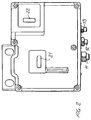
- Figure 2 illustrates a top plan view of the top portion of the housing or casing of the device according to the invention. This figure, in particular, clearly shows a first manually operated switch 21 and a second manually operated switch 22, the functions of which will be disclosed in a more detailed manner hereinafter.
- Figure 3 illustrates a top plan view of the bottom portion of the casing of the device according to the invention.
- this figure clearly shows the attachment of the clamp 2 by means of which the device is coupled to the positive post of the battery (not shown).
- the outputs 11, 12, 13, 14 and input 17 are moreover shown.
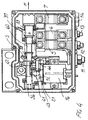
- Figure 4 is a top plan view illustrating the inside of the inventive device.
- the electric contacts 3 and 4 are coupled to a coupling rod 60, which can be driven in the direction of the arrow "F" under the control of a first spring 36, a second spring 38 and a third spring 39.
- Said coupling rod is moreover provided with a first edge 37 and a second edge 40, both said first and second edges 37, 40 being adapted to be engaged, through the springs 38 and 39, with the contacts 3 and 4, in order to separate said contacts from the respective portions of the power supply circuit 1.
- Figure 4 shows moreover, by a partial cross section, a groove 41 and a recess 42 formed in said coupling rod 60.
- a groove 41 is engaged, under the urging of a related spring, an end portion of a movable core 51 pertaining to the electromagnet 16, whereas in the recess 42 is engaged one end portion of a first switch 21 which is held engaged with said rod 60 by a manually operated spring 44.
- Figure 5.a schematically illustrates the electromechanic device according to the invention in the operation mode thereof in which both said contacts close the respective circuit portions.
- the coupling rod 60 is provided with the recess 42 in which an end portion 81 of the manually operated switch 21 is engaged.
- the coupling rod 60 is moreover formed with a groove 41 in which an end 80 of the movable core 51 of the electromagnet 16 is engaged, said end portion also operating as a stop element, with respect to the forces provided by the springs 36, 38 and 39.
- Figure 5.a further shows the second switch 22 in a coupled circuit condition.
- the inertial switch suitably coupled to the input 17, conveying a ground signal to the electromagnet 16, will be actuated.
- the first contact 3 will be removed or separated from the first circuit portion 15, thereby switching-off the power supply of the main electric system of the vehicle.
- the coupling rod 60 in particular, will be held in this position by a portion of the recess 42 engaging with the end portion 81 of the manually operated switch 21.
- the recess 42 will be further disengaged from the coupling rod 60, thereby allowing said coupling rod 60 to be further driven as urged by the spring 36, to cause the contact 4 to be separated from the respective second circuit portion 16 power supplying the privilege loads.
- the first contact 3 is separated under the operation of the spring 39 of an edge 37, rigid with said rod 60, whereas the second contact 4 is separated, preferably, by the operation of the spring 38 of an edge 40 also rigid with the rod 60.
- the switch 21 can also be used for switching-off the battery by a single operation, since said switch is provided with a fork element 50 engaging with the movable core 51 of the electromagnet, thereby allowing to simultaneously disengage the groove 41 and recess 42.
- the coupling rod 60 can be caused to return both to the position thereof in which only the second contact 4 will close the corresponding second circuit portion 16 and to the position thereof in which the circuit will be fully closed.
Landscapes
- Engineering & Computer Science (AREA)
- Chemical & Material Sciences (AREA)
- Combustion & Propulsion (AREA)
- Transportation (AREA)
- Mechanical Engineering (AREA)
- Electric Propulsion And Braking For Vehicles (AREA)
- Mechanisms For Operating Contacts (AREA)
Applications Claiming Priority (2)
| Application Number | Priority Date | Filing Date | Title |
|---|---|---|---|
| IT97MI001396A IT1292153B1 (it) | 1997-06-12 | 1997-06-12 | Dispositivo elettromeccanico perfezionato per il sezionamento della batteria di un veicolo a motore |
| ITMI971396 | 1997-06-12 |
Publications (2)
| Publication Number | Publication Date |
|---|---|
| EP0885779A2 true EP0885779A2 (de) | 1998-12-23 |
| EP0885779A3 EP0885779A3 (de) | 2001-10-17 |
Family
ID=11377356
Family Applications (1)
| Application Number | Title | Priority Date | Filing Date |
|---|---|---|---|
| EP98110595A Withdrawn EP0885779A3 (de) | 1997-06-12 | 1998-06-09 | Elektromechanische Vorrichtung zur Batterieabschaltung in einem Kraftfahrzeug |
Country Status (2)
| Country | Link |
|---|---|
| EP (1) | EP0885779A3 (de) |
| IT (1) | IT1292153B1 (de) |
Family Cites Families (2)
| Publication number | Priority date | Publication date | Assignee | Title |
|---|---|---|---|---|
| DE3327532A1 (de) * | 1983-07-30 | 1985-02-07 | Iveco Magirus AG, 7900 Ulm | Trennschalteinrichtung fuer kraftfahrzeuge |
| US5574316A (en) * | 1995-08-31 | 1996-11-12 | Nieschulz; Emil W. | Vehicle battery disabling apparatus |
-
1997
- 1997-06-12 IT IT97MI001396A patent/IT1292153B1/it active IP Right Grant
-
1998
- 1998-06-09 EP EP98110595A patent/EP0885779A3/de not_active Withdrawn
Non-Patent Citations (1)
| Title |
|---|
| None |
Also Published As
| Publication number | Publication date |
|---|---|
| ITMI971396A1 (it) | 1998-12-14 |
| ITMI971396A0 (de) | 1997-06-12 |
| IT1292153B1 (it) | 1999-01-25 |
| EP0885779A3 (de) | 2001-10-17 |
Similar Documents
| Publication | Publication Date | Title |
|---|---|---|
| US6049140A (en) | Battery disconnection system | |
| US4149093A (en) | Battery protection device | |
| US5552642A (en) | Protection system with voltage switching | |
| EP0602804B1 (de) | Elektrische Verbindung und Verriegelungsschaltungssystem für den elektrischen Antrieb eines Fahrzeuges | |
| US10137783B2 (en) | High-voltage vehicle network of a motor vehicle, quick-break switch and method of operating the high-voltage vehicle network | |
| EP1052149A2 (de) | Verfahren zum Betrieb einer Sicherheitseinrichtung für Kraftfahrzeuge | |
| US6333568B1 (en) | Switching arrangement and process for switching off an electric energy source of a vehicle | |
| US5838136A (en) | 3-pole battery switches | |
| US6597149B1 (en) | Battery system | |
| EP0786378A2 (de) | Automatische Notbeleuchtungssteuerung für Fahrzeuge | |
| EP0885779A2 (de) | Elektromechanische Vorrichtung zur Batterieabschaltung in einem Kraftfahrzeug | |
| EP0931701B1 (de) | Trennungssystem für eine Batterie | |
| JP3551586B2 (ja) | コンデンサ放電回路 | |
| US4644180A (en) | Actuator emergency operation | |
| GB2283137A (en) | Arrangement for preventing driving of a battery powered vehicle during charging | |
| US5808848A (en) | Digital circuit interrupter shunt trip accessory module | |
| CA2009186A1 (en) | Braking system and break-away braking system | |
| EP0727335B1 (de) | Sicherheitstrennungsschalter zur automatischen Trennung elektrischer Lasten in Kraftfahrzeugen oder dergleichen | |
| US3152259A (en) | Protective circuit for electrical systems on automotive vehicles | |
| DE19922332C1 (de) | Sicherheitseinrichtung für Fahrzeuge | |
| EP0632558A1 (de) | Schutzeinrichtung mit automatischer Rückstellung gegen Kurzschlüsse in elektrischen Systemen an Bord von Kraftfahrzeuge | |
| WO1994004394A1 (en) | 3-pole battery switches | |
| EP0628980B1 (de) | Trägheitsgerät zur Ausschaltung der Batterie eines Kraftfahrzeuges | |
| EP0655037A1 (de) | Schalter für dreipolige batterien. | |
| US4613801A (en) | Trolling motor foot control with arc suppressor |
Legal Events
| Date | Code | Title | Description |
|---|---|---|---|
| PUAI | Public reference made under article 153(3) epc to a published international application that has entered the european phase |
Free format text: ORIGINAL CODE: 0009012 |
|
| AK | Designated contracting states |
Kind code of ref document: A2 Designated state(s): AT BE CH CY DE DK ES FI FR GB GR IE IT LI LU MC NL PT SE Kind code of ref document: A2 Designated state(s): DE ES FR GB |
|
| AX | Request for extension of the european patent |
Free format text: AL;LT;LV;MK;RO;SI |
|
| PUAL | Search report despatched |
Free format text: ORIGINAL CODE: 0009013 |
|
| AK | Designated contracting states |
Kind code of ref document: A3 Designated state(s): AT BE CH CY DE DK ES FI FR GB GR IE IT LI LU MC NL PT SE |
|
| AX | Request for extension of the european patent |
Free format text: AL;LT;LV;MK;RO;SI |
|
| 17P | Request for examination filed |
Effective date: 20011221 |
|
| AKX | Designation fees paid |
Free format text: DE ES FR GB |
|
| STAA | Information on the status of an ep patent application or granted ep patent |
Free format text: STATUS: THE APPLICATION HAS BEEN WITHDRAWN |
|
| 18W | Application withdrawn |
Effective date: 20030731 |