EP1294054A2 - Zugfederklemme mit Prüfabgriff - Google Patents
Zugfederklemme mit Prüfabgriff Download PDFInfo
- Publication number
- EP1294054A2 EP1294054A2 EP02014287A EP02014287A EP1294054A2 EP 1294054 A2 EP1294054 A2 EP 1294054A2 EP 02014287 A EP02014287 A EP 02014287A EP 02014287 A EP02014287 A EP 02014287A EP 1294054 A2 EP1294054 A2 EP 1294054A2
- Authority
- EP
- European Patent Office
- Prior art keywords
- tension spring
- leg
- spring
- current bar
- opening
- Prior art date
- Legal status (The legal status is an assumption and is not a legal conclusion. Google has not performed a legal analysis and makes no representation as to the accuracy of the status listed.)
- Granted
Links
- 239000000523 sample Substances 0.000 title abstract 2
- 238000012360 testing method Methods 0.000 claims abstract description 49
- 239000004020 conductor Substances 0.000 claims description 15
- 238000003780 insertion Methods 0.000 claims description 8
- 230000037431 insertion Effects 0.000 claims description 8
- 230000015572 biosynthetic process Effects 0.000 claims description 3
- 238000007906 compression Methods 0.000 claims description 3
- 230000006835 compression Effects 0.000 claims description 2
- 239000002184 metal Substances 0.000 abstract 1
- 230000000717 retained effect Effects 0.000 abstract 1
- 239000000463 material Substances 0.000 description 2
- 230000000881 depressing effect Effects 0.000 description 1
- 238000005259 measurement Methods 0.000 description 1
- 230000003313 weakening effect Effects 0.000 description 1
Images


Classifications
-
- H—ELECTRICITY
- H01—ELECTRIC ELEMENTS
- H01R—ELECTRICALLY-CONDUCTIVE CONNECTIONS; STRUCTURAL ASSOCIATIONS OF A PLURALITY OF MUTUALLY-INSULATED ELECTRICAL CONNECTING ELEMENTS; COUPLING DEVICES; CURRENT COLLECTORS
- H01R4/00—Electrically-conductive connections between two or more conductive members in direct contact, i.e. touching one another; Means for effecting or maintaining such contact; Electrically-conductive connections having two or more spaced connecting locations for conductors and using contact members penetrating insulation
- H01R4/28—Clamped connections, spring connections
- H01R4/48—Clamped connections, spring connections utilising a spring, clip, or other resilient member
- H01R4/4809—Clamped connections, spring connections utilising a spring, clip, or other resilient member using a leaf spring to bias the conductor toward the busbar
- H01R4/484—Spring housing details
- H01R4/4842—Spring housing details the spring housing being provided with a single opening for insertion of a spring-activating tool
-
- H—ELECTRICITY
- H01—ELECTRIC ELEMENTS
- H01R—ELECTRICALLY-CONDUCTIVE CONNECTIONS; STRUCTURAL ASSOCIATIONS OF A PLURALITY OF MUTUALLY-INSULATED ELECTRICAL CONNECTING ELEMENTS; COUPLING DEVICES; CURRENT COLLECTORS
- H01R2201/00—Connectors or connections adapted for particular applications
- H01R2201/20—Connectors or connections adapted for particular applications for testing or measuring purposes
-
- H—ELECTRICITY
- H01—ELECTRIC ELEMENTS
- H01R—ELECTRICALLY-CONDUCTIVE CONNECTIONS; STRUCTURAL ASSOCIATIONS OF A PLURALITY OF MUTUALLY-INSULATED ELECTRICAL CONNECTING ELEMENTS; COUPLING DEVICES; CURRENT COLLECTORS
- H01R4/00—Electrically-conductive connections between two or more conductive members in direct contact, i.e. touching one another; Means for effecting or maintaining such contact; Electrically-conductive connections having two or more spaced connecting locations for conductors and using contact members penetrating insulation
- H01R4/28—Clamped connections, spring connections
- H01R4/48—Clamped connections, spring connections utilising a spring, clip, or other resilient member
- H01R4/4809—Clamped connections, spring connections utilising a spring, clip, or other resilient member using a leaf spring to bias the conductor toward the busbar
- H01R4/4811—Spring details
- H01R4/4816—Spring details the spring shape preventing insertion of the conductor end when the spring is unbiased
Definitions
- the invention relates to a tension spring clamp a housing in which the tension spring with its Support leg is arranged on a current bar, the through a clamping window in the front section of the Spring leg of the tension spring protrudes.
- This housing points against that in the clamping position below the Current bar open area of the terminal window in the Spring leg a conductor insertion opening and above in Height of the upper part of the vertex to the support leg bent spring leg an actuation opening for Insert one of the spring legs towards the support leg depressing tool.
- the housing between the conductor insertion opening and the Actuating opening a test tap opening for Pushing through a contacting the current bar Contact pin of a test plug.
- the invention is therefore based on the object To create tension spring clamps of the type mentioned at the outset, in which a secure contact of the contact pin of the Test plug with the current bar in the inserted position is also given when the test plug is released becomes.
- This task is performed with a tension spring clamp Generic type solved according to the invention that the test tap opening for guiding the Contact pin of the test plug, hollow cylindrical is formed, the extension of Cylinder axis along the one away from the current bar Extends inside the support leg of the tension spring, further in that in the end section of the spring leg the tension spring next to the clamp window Push-through opening for the contact pin of the test plug is present and also in that the current bar one that extends into the plug-in path Forming has that introduced to it Contact pin of the test tap opening Test plug is pressed against the long side.
- the push-through opening in the front section of the Spring leg of the tension spring sufficient play Offer.
- This push-through opening is therefore expedient as an elongated hole in the direction of the travel of the Formed end portion of the spring leg, and goes this slot in the clamp window of the spring leg about.
- the tension spring clamp On the Current bar required.
- the support leg the tension spring expediently a through hole through which the Formation protrudes on the current bar, which on this Through hole is positively adjusted. So the shape on the current bar has a double function, by not just contacting the contact pin of the test plug but also the mechanical fuse the tension spring serves.
- the invention consists of the shape in the current bar an embossed hump that is compressed and thus in the area of its free end on the inside of the support leg over the edge of its through hole attacks.
- a groove-shaped contour be embossed, in particular a V-groove, in the Area the contact with the contact pin of the Test plug is made by the contact pin with its Longitude on the flanks of this contour.
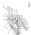
- FIGS. 1 and 2 show a clamping housing 1 which is usually made of plastic and in which a tension spring 2 is arranged.
- the tension spring 2 has a support leg 3 with which it is placed on a current bar 4 .
- the one-piece, loop-shaped tension spring 2 also has a spring leg 5 , which has an end section 6 with a clamping window 7 .
- the end section 6 of the spring leg 5 extends approximately perpendicular to the support leg 3 .
- the current bar 4 has a front end 20 which projects through the clamping window 7 in the end section 6 of the spring leg 5 .
- the clamping window 7 is widened because the clamping window 7 is followed by a push-through opening 14 which has the shape of an elongated hole which is open at one end.
- the width of the push-through opening 14 in the width direction of the end section 6 of the spring leg 5 is smaller than the width of the clamping window 7 in order to keep the material weakening of the tension spring leg 5 low.
- the housing 1 has a conductor insertion opening 8 which specifies a plug-in direction for the end 18 of a stripped conductor 19 to be passed through, which extends along the side of the current bar 4 which lies away from the support leg 3 of the tension spring 2 lying thereon.
- a conductor insertion opening 8 specifies a plug-in direction for the end 18 of a stripped conductor 19 to be passed through, which extends along the side of the current bar 4 which lies away from the support leg 3 of the tension spring 2 lying thereon.
- the clamping window 7 thereby moves in the end section 6 of the spring leg 5 and opens below the front end 20 of the power terminal. 4
- the spring leg 5 is pressed down by means of a tool which can be inserted into the interior of the housing 1 through an actuation opening 9 .
- This actuation opening 9 is located on the front side of the housing 1 in accordance with the representations of FIGS. 1 and 2 , while the conductor insertion opening 8 on the front side of the housing 1 is shown lying down. After removing the tool, the spring end 5 clamps the conductor end back against the underside of the current bar 4 for the purpose of contacting.
- test tap opening 10 On the end face of the terminal housing 1.
- This test tap opening 10 is hollow-cylindrical molded in the material of the housing 1 and serves to guide a contact pin 11 of a test plug 12 , which is inserted into the interior of the device Tension spring 2 protrudes.
- the cylinder axis A of the test tap opening 10 and correspondingly that of the contact pin 11 guided therein runs above the inside 13 of the support leg 3 of the tension spring 2 and thus on that side of the support leg 3 which lies away from the current bar. So that when the clamping leg 5 is compressed, the contact pin 11 of the test plug 12 does not collide with the end section 6 thereof, the through-hole 14 mentioned is present, which widens the clamping window 7 in the end section 6 of the spring leg 5 .
- the contact pin 11 of the test plug 12 passed through the test tap opening 10 passes through the clamping window 7 of the spring leg 5 of the tension spring when a conductor is not being clamped straight on.
- the through opening 14 on the end section 6 of the spring leg 5 receives the contact pin 11 which projects into the interior of the tension spring.
- the tension spring 2 is held securely on the current bar 4 .
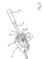
- a shape 15 in the form of a hump is present on the current bar 4 , onto which the support leg 3 of the tension spring 2 is attached with a through hole 16 correspondingly adapted to it in a form-fitting manner.
- the through hole 16 is overlapped on the inner side 13 of the Auflagerschenkels 3 in the edge region, is fixed whereby the tension spring 2 against lifting from the current bar. 4
- This particular shape 15 of the current bar 4 has the advantage that the contact pin 11 of the test plug 12, which is inserted into the interior of the tension spring 2 and is automatically held in the test tap opening 11 , can contact the current bar.
- the contact pin 11 runs onto the formation 15 of the current bar 4, there is a slight radial deflection of the correspondingly elastic contact pin 11 , whereby, in view of the exact guidance of the contact pin 11 in the test tap opening 10 in the direction of the axis A, a pressure is exerted on the contact pin 11 ,
- the test plug 12 can be released at the test tap, which offers handling advantages for clamping and testing work.
- the secure hold of the contact pin 11 of the test plug 12 is independent of whether or not a conductor is clamped to the current bar 4 by means of the tension spring 2 .
Landscapes
- Measuring Leads Or Probes (AREA)
- Details Of Connecting Devices For Male And Female Coupling (AREA)
- Testing Of Individual Semiconductor Devices (AREA)
- Clamps And Clips (AREA)
- Supports For Pipes And Cables (AREA)
- Blow-Moulding Or Thermoforming Of Plastics Or The Like (AREA)
Abstract
Description
- Fig. 1
- eine perspektivische Darstellung einer Zugfederklemme mit aufgeschnittenem Gehäuse,
- Fig. 2
- eine weitere perspektivische Darstellung der Zugfederklemme mit aufgeschnittenem Gehäuse nach Figur 1, jedoch unter einem anderen Blickwinkel,
- Fig. 3
- eine perspektivische Darstellung der auf den Strombalken aufgesetzten Zugfeder der Zugfederklemme nach den Figuren 1 und 2 und
- Fig. 4
- eine perspektivische Darstellung der Zugfeder gemäß Figur 3, jedoch in der Klemmlage bei eingeführtem Prüfstecker.
Claims (6)
- Zugfederklemme mit einem Gehäuse (1 ), in welchem die Zugfeder (2 ) mit ihrem Auflagerschenkel (3 ) auf einem Strombalken (4 ) angeordnet ist, der durch ein Klemmfenster (7 ) im Stirnabschnitt (6 ) des Federschenkels (5 ) der Zugfeder (2 ) hindurchragt, und welches gegenüber dem in der Klemmlage unterhalb des Strombalkens (4 ) offenen Bereichs des Klemmfensters (7 ) im Federschenkel (5 ) eine Leitereinstecköffnung (8 ) und darüber in Höhe des oberen Scheitelbereichs des zum Auflagerschenkel hin gebogenen Federschenkels (5 ) eine Betätigungsöffnung (9 ) zum Einführen eines den Federschenkel (5 ) zum Auflagerschenkel (3 ) hin niederdrückenden Werkzeugs aufweist, wobei das Gehäuse (1 ) ferner zwischen der Leitereinstecköffnung (8 ) und der Betätigungsöffnung (9 ) eine Prüfabgriffsöffnung (10 ) zum Durchstecken eines den Strombalken (4 ) kontaktierenden Kontaktstiftes (11 ) eines Prüfsteckers (12 ) hat,
dadurch gekennzeichnet , dass die Prüfabgriffsöffnung (10 ) zur Führung des Kontaktstiftes (11 ) des Prüfsteckers (12 ) hohlzylindrisch ausgebildet ist, wobei sich die Verlängerung der Zylinderachse (A) entlang der vom Strombalken (3 ) wegliegenden Innenseite (13 ) des Auflagerschenkels (3 ) der Zugfeder (2 ) erstreckt, dass im Stirnabschnitt (6 ) des Federschenkels (5 ) der Zugfeder (2 ) neben dem Klemmfenster (7 ) eine Durchstecköffnung (14 ) für den Kontaktstift (11 ) des Prüfsteckers (12 ) vorhanden ist und dass der Strombalken (4 ) eine derart bis in den Steckweg des Kontaktstiftes (11 ) hineinreichende Ausformung (15 ) hat, dass daran der eingeführte, in der Prüfabgriffsöffnung (10 ) gehaltene Kontaktstift (11 ) des Prüfsteckers (12 ) längsseitig mit Zwang anliegt. - Zugfederklemme nach Anspruch 1,
dadurch gekennzeichnet, dass die Durchstecköffnung (14 ) im Stirnabschnitt (6 ) des Federschenkels (5 ) der Zugfeder (2 ) ein sich ein in Richtung des Federweges dieses Stirnabschnittes (6 ) erstreckendes Langloch ist. - Zugfederklemme nach Anspruch 2,
dadurch gekennzeichnet, dass die Durchstecköffnung (14 ) an ihrem einen Ende in das Klemmfenster (7 ) des Federschenkels (5 ) der Zugfeder (2 ) übergeht. - Zugfederklemme nach einem der Ansprüche 1-3,
dadurch gekennzeichnet, dass der Auflagerschenkel (3 ) der Zugfeder (2 ) ein Durchgangsloch (16 ) hat, durch das die Ausformung (15 ) am Strombalken (4 ) hindurchragt, die an dieses Durchgangsloch (16 ) formschlüssig angepasst ist. - Zugfederklemme nach Anspruch 4,
dadurch gekennzeichnet, dass die Ausformung (15 ) ein in den Strombalken (4 ) eingeprägter Höcker ist, der an der Innenseite (13 ) des Auflagerschenkels (3 ) der Zugfeder (2 ) eine über den Rand dessen Durchgangslochs (16 ) hinausreichende Stauchung hat. - Zugfederklemme nach Anspruch 4 oder 5,
dadurch gekennzeichnet, dass die Ausformung (15 ) des Strombalkens (4 ) an ihrer freien Stirnseite eine diametrale, nutförmige Kontur (17 ) zur Kontaktierung mit dem Kontaktstift (11 ) des Prüfsteckers (12 ) hat.
Applications Claiming Priority (2)
| Application Number | Priority Date | Filing Date | Title |
|---|---|---|---|
| DE20115100U DE20115100U1 (de) | 2001-09-13 | 2001-09-13 | Zugfederklemme mit Prüfabgriff |
| DE20115100U | 2001-09-13 |
Publications (3)
| Publication Number | Publication Date |
|---|---|
| EP1294054A2 true EP1294054A2 (de) | 2003-03-19 |
| EP1294054A3 EP1294054A3 (de) | 2003-08-13 |
| EP1294054B1 EP1294054B1 (de) | 2007-10-03 |
Family
ID=7961652
Family Applications (1)
| Application Number | Title | Priority Date | Filing Date |
|---|---|---|---|
| EP02014287A Expired - Lifetime EP1294054B1 (de) | 2001-09-13 | 2002-06-27 | Zugfederklemme mit Prüfabgriff |
Country Status (5)
| Country | Link |
|---|---|
| US (1) | US6750402B2 (de) |
| EP (1) | EP1294054B1 (de) |
| CN (1) | CN1208877C (de) |
| AT (1) | ATE375019T1 (de) |
| DE (2) | DE20115100U1 (de) |
Cited By (1)
| Publication number | Priority date | Publication date | Assignee | Title |
|---|---|---|---|---|
| DE102006038253A1 (de) * | 2006-08-16 | 2008-02-21 | Hirschmann Automation And Control Gmbh | Elektrische Steckverbindung |
Families Citing this family (18)
| Publication number | Priority date | Publication date | Assignee | Title |
|---|---|---|---|---|
| DE102004040859B4 (de) * | 2004-08-23 | 2007-03-15 | Phoenix Contact Gmbh & Co. Kg | Elektrische Reihenklemme und Prüfstecker zur Verwendung bei einer elektrischen Klemme |
| US7806736B2 (en) * | 2008-07-01 | 2010-10-05 | Leviton Manufacturing Co., Inc. | Wiring device terminal and related method of termination |
| US7909664B2 (en) * | 2009-05-29 | 2011-03-22 | Leviton Manufacturing Co., Inc. | Wire termination apparatus and method |
| US8047883B2 (en) | 2009-05-29 | 2011-11-01 | Leviton Manufacturing Co., Inc. | Wire termination mechanisms and methods of use |
| US8137145B2 (en) * | 2009-05-29 | 2012-03-20 | Leviton Manufacturing Co., Inc. | Wiring termination mechanisms and use thereof |
| US7963812B2 (en) | 2009-05-29 | 2011-06-21 | Leviton Manufacturing Co., Inc. | Wire termination apparatus and method |
| DE102010048698B4 (de) * | 2010-10-19 | 2014-12-18 | Wago Verwaltungsgesellschaft Mbh | Elektrische Verbindungsklemme |
| WO2013110363A1 (de) | 2012-01-26 | 2013-08-01 | Pepperl + Fuchs Gmbh | Zugfeder-schraub-klemme |
| US9130285B2 (en) * | 2012-09-05 | 2015-09-08 | Hubbell Incorporated | Push wire connector having a spring biasing member |
| CN103001024A (zh) * | 2012-12-04 | 2013-03-27 | 上海友邦电气(集团)股份有限公司 | 一种用于低压电器接线模块的笼式弹簧卡紧模块 |
| US9553387B2 (en) * | 2014-07-15 | 2017-01-24 | Industria Lombarda Materiale Elettrico—I.L.M.E. S.P.A. | Electrical connecting device with spring connection element and compact actuator and multi-pole plug connector comprising a plurality of said spring contacts |
| DE102016208291B4 (de) | 2016-05-13 | 2023-09-07 | Zf Friedrichshafen Ag | Federklammer, Montagewerkzeug sowie Verfahren zum Fixieren von Kontaktpartnern und Verbindungssystem zum Herstellen einer elektrischen und mechanischen Verbindung zwischen Kontaktpartnern |
| US10461444B2 (en) | 2017-01-06 | 2019-10-29 | Hubbell Incorporated | Electrical wiring devices with screwless connection terminals |
| US11495895B2 (en) | 2019-05-01 | 2022-11-08 | Hubbell Incorporated | Terminations for electrical wiring devices |
| CN112701501B (zh) * | 2019-10-23 | 2022-08-09 | 国网天津市电力公司 | 一种新型断路器回路电阻测试仪接头 |
| MX2024003613A (es) | 2021-09-27 | 2024-04-09 | Hubbell Inc | Terminales de conexion sin tornillos con administrador de cables. |
| WO2023177811A1 (en) | 2022-03-16 | 2023-09-21 | Hubbell Incorporated | Electrical wiring devices with screwless wire terminals |
| CN120858493A (zh) | 2022-11-16 | 2025-10-28 | 豪倍公司 | 具有线材端接组件的多极电气布线装置 |
Family Cites Families (9)
| Publication number | Priority date | Publication date | Assignee | Title |
|---|---|---|---|---|
| FR1602459A (de) * | 1968-10-23 | 1970-11-30 | ||
| US4351583A (en) * | 1980-06-19 | 1982-09-28 | Gte Products Corporation | Electrical terminal |
| US4964811A (en) * | 1988-08-25 | 1990-10-23 | Amp Incorporated | Electrical junction connector having wire-receiving slots |
| US6015953A (en) * | 1994-03-11 | 2000-01-18 | Tohoku Electric Power Co., Inc. | Tension clamp for stranded conductor |
| US5777269A (en) * | 1996-09-13 | 1998-07-07 | G & H Technology, Inc. | Termination for a shielded cable |
| FR2785340B1 (fr) * | 1998-11-03 | 2001-01-26 | Metal Deploye Sa | Dispositif de fixation d'un fil sur un element porteur muni d'au moins une ouverture et ensemble porteur pour chemin de cables comportant au moins un tel dispositif |
| US6323430B1 (en) * | 1999-07-28 | 2001-11-27 | Itt Manufacturing Enterprises, Inc. | S-shaped cable holding clamp with grounding |
| DE20106710U1 (de) * | 2001-04-18 | 2001-08-09 | Phoenix Contact Gmbh & Co., 32825 Blomberg | Elektrische Klemme |
| US6512179B1 (en) * | 2001-09-28 | 2003-01-28 | International Business Machines Corporation | Transmission cable strain relief device |
-
2001
- 2001-09-13 DE DE20115100U patent/DE20115100U1/de not_active Expired - Lifetime
-
2002
- 2002-06-27 DE DE50211002T patent/DE50211002D1/de not_active Expired - Lifetime
- 2002-06-27 EP EP02014287A patent/EP1294054B1/de not_active Expired - Lifetime
- 2002-06-27 AT AT02014287T patent/ATE375019T1/de not_active IP Right Cessation
- 2002-09-13 CN CN02143105.1A patent/CN1208877C/zh not_active Expired - Fee Related
- 2002-10-29 US US10/223,738 patent/US6750402B2/en not_active Expired - Fee Related
Non-Patent Citations (1)
| Title |
|---|
| None |
Cited By (1)
| Publication number | Priority date | Publication date | Assignee | Title |
|---|---|---|---|---|
| DE102006038253A1 (de) * | 2006-08-16 | 2008-02-21 | Hirschmann Automation And Control Gmbh | Elektrische Steckverbindung |
Also Published As
| Publication number | Publication date |
|---|---|
| CN1405926A (zh) | 2003-03-26 |
| DE20115100U1 (de) | 2001-11-29 |
| US20030047346A1 (en) | 2003-03-13 |
| EP1294054B1 (de) | 2007-10-03 |
| US6750402B2 (en) | 2004-06-15 |
| DE50211002D1 (de) | 2007-11-15 |
| CN1208877C (zh) | 2005-06-29 |
| EP1294054A3 (de) | 2003-08-13 |
| ATE375019T1 (de) | 2007-10-15 |
Similar Documents
| Publication | Publication Date | Title |
|---|---|---|
| EP1294054B1 (de) | Zugfederklemme mit Prüfabgriff | |
| EP3504755B1 (de) | Federkraftklemmanschluss | |
| DE102007059096B4 (de) | Elektrodenklemme zum elektrischen Kontaktieren einer Filmelektrode und einer Druckknopfelektrode | |
| EP1111720A1 (de) | Schraubenlose Anschlussklemme | |
| EP3504756B1 (de) | Anschlussklemme | |
| CH663861A5 (de) | Abisolierzange fuer leiterenden. | |
| EP0335093B1 (de) | Schraubenlose elektrische Anschlussklemme | |
| DE19737947A1 (de) | Reihenklemme zum abisolierungsfreien Anschluß isolierter Leiter | |
| DE3406081A1 (de) | Federdruckklemme fuer elektrische leiter | |
| DE102006018129A1 (de) | Federkraftklemme mit einer in einem Gehäuse angeordneten Schenkelfeder | |
| DE10119652A1 (de) | Schraubenlose Anschlussklemme | |
| DE3238898C1 (de) | Entklammerungszange | |
| DE102015004160A1 (de) | Test-Contactor, Verfahren und Verwendung | |
| DE102019106352B4 (de) | Leiteranschlussklemme mit einem Betätigungselement umfassend ein Mitnehmerelement | |
| DE19510173C1 (de) | Schraubenlose Anschlußklemme | |
| EP3446365B1 (de) | Elektrische anschlussklemme und verfahren | |
| DE60313190T2 (de) | Anschlussklemme und Kabelanschlussverbinder | |
| DE102021130873A1 (de) | Anschlussanordnung und Anschlussklemme | |
| DE10054290C2 (de) | Schraubenlose Anschlussklemme | |
| DE10205613B4 (de) | Kontaktelement | |
| EP0141086B1 (de) | Anschlussklemme für Niederspannungsanlage, insbesondere Schaltgeräte | |
| DE2416441C3 (de) | ||
| DE19752882A1 (de) | Elektrische Anschlußklemme | |
| EP1204164B1 (de) | Schraubenlose Anschlussklemmenanordnung sowie elektrischer Apparat mit einer solchen | |
| DE19610610A1 (de) | Anordnung zur Verbindung eines elektrischen Leiters mit einem Schneidklemmkontakt |
Legal Events
| Date | Code | Title | Description |
|---|---|---|---|
| PUAI | Public reference made under article 153(3) epc to a published international application that has entered the european phase |
Free format text: ORIGINAL CODE: 0009012 |
|
| AK | Designated contracting states |
Kind code of ref document: A2 Designated state(s): AT BE CH CY DE DK ES FI FR GB GR IE IT LI LU MC NL PT SE TR |
|
| AX | Request for extension of the european patent |
Extension state: AL LT LV MK RO SI |
|
| PUAL | Search report despatched |
Free format text: ORIGINAL CODE: 0009013 |
|
| AK | Designated contracting states |
Designated state(s): AT BE CH CY DE DK ES FI FR GB GR IE IT LI LU MC NL PT SE TR |
|
| AX | Request for extension of the european patent |
Extension state: AL LT LV MK RO SI |
|
| 17P | Request for examination filed |
Effective date: 20040204 |
|
| AKX | Designation fees paid |
Designated state(s): AT BE CH CY DE DK ES FI FR GB GR IE IT LI LU MC NL PT SE TR |
|
| GRAP | Despatch of communication of intention to grant a patent |
Free format text: ORIGINAL CODE: EPIDOSNIGR1 |
|
| GRAS | Grant fee paid |
Free format text: ORIGINAL CODE: EPIDOSNIGR3 |
|
| GRAA | (expected) grant |
Free format text: ORIGINAL CODE: 0009210 |
|
| AK | Designated contracting states |
Kind code of ref document: B1 Designated state(s): AT BE CH CY DE DK ES FI FR GB GR IE IT LI LU MC NL PT SE TR |
|
| REG | Reference to a national code |
Ref country code: GB Ref legal event code: FG4D Free format text: NOT ENGLISH |
|
| REG | Reference to a national code |
Ref country code: CH Ref legal event code: EP |
|
| REG | Reference to a national code |
Ref country code: IE Ref legal event code: FG4D Free format text: LANGUAGE OF EP DOCUMENT: GERMAN |
|
| REF | Corresponds to: |
Ref document number: 50211002 Country of ref document: DE Date of ref document: 20071115 Kind code of ref document: P |
|
| NLV1 | Nl: lapsed or annulled due to failure to fulfill the requirements of art. 29p and 29m of the patents act | ||
| GBV | Gb: ep patent (uk) treated as always having been void in accordance with gb section 77(7)/1977 [no translation filed] | ||
| PG25 | Lapsed in a contracting state [announced via postgrant information from national office to epo] |
Ref country code: SE Free format text: LAPSE BECAUSE OF FAILURE TO SUBMIT A TRANSLATION OF THE DESCRIPTION OR TO PAY THE FEE WITHIN THE PRESCRIBED TIME-LIMIT Effective date: 20080103 Ref country code: ES Free format text: LAPSE BECAUSE OF FAILURE TO SUBMIT A TRANSLATION OF THE DESCRIPTION OR TO PAY THE FEE WITHIN THE PRESCRIBED TIME-LIMIT Effective date: 20080114 Ref country code: NL Free format text: LAPSE BECAUSE OF FAILURE TO SUBMIT A TRANSLATION OF THE DESCRIPTION OR TO PAY THE FEE WITHIN THE PRESCRIBED TIME-LIMIT Effective date: 20071003 |
|
| ET | Fr: translation filed | ||
| PG25 | Lapsed in a contracting state [announced via postgrant information from national office to epo] |
Ref country code: PT Free format text: LAPSE BECAUSE OF FAILURE TO SUBMIT A TRANSLATION OF THE DESCRIPTION OR TO PAY THE FEE WITHIN THE PRESCRIBED TIME-LIMIT Effective date: 20080303 |
|
| REG | Reference to a national code |
Ref country code: IE Ref legal event code: FD4D |
|
| PG25 | Lapsed in a contracting state [announced via postgrant information from national office to epo] |
Ref country code: DK Free format text: LAPSE BECAUSE OF FAILURE TO SUBMIT A TRANSLATION OF THE DESCRIPTION OR TO PAY THE FEE WITHIN THE PRESCRIBED TIME-LIMIT Effective date: 20071003 |
|
| PLBE | No opposition filed within time limit |
Free format text: ORIGINAL CODE: 0009261 |
|
| STAA | Information on the status of an ep patent application or granted ep patent |
Free format text: STATUS: NO OPPOSITION FILED WITHIN TIME LIMIT |
|
| 26N | No opposition filed |
Effective date: 20080704 |
|
| PG25 | Lapsed in a contracting state [announced via postgrant information from national office to epo] |
Ref country code: IE Free format text: LAPSE BECAUSE OF FAILURE TO SUBMIT A TRANSLATION OF THE DESCRIPTION OR TO PAY THE FEE WITHIN THE PRESCRIBED TIME-LIMIT Effective date: 20071003 |
|
| PG25 | Lapsed in a contracting state [announced via postgrant information from national office to epo] |
Ref country code: GB Free format text: LAPSE BECAUSE OF FAILURE TO SUBMIT A TRANSLATION OF THE DESCRIPTION OR TO PAY THE FEE WITHIN THE PRESCRIBED TIME-LIMIT Effective date: 20071003 |
|
| BERE | Be: lapsed |
Owner name: PHOENIX CONTACT G.M.B.H. & CO. KG Effective date: 20080630 |
|
| PG25 | Lapsed in a contracting state [announced via postgrant information from national office to epo] |
Ref country code: GR Free format text: LAPSE BECAUSE OF FAILURE TO SUBMIT A TRANSLATION OF THE DESCRIPTION OR TO PAY THE FEE WITHIN THE PRESCRIBED TIME-LIMIT Effective date: 20080104 Ref country code: MC Free format text: LAPSE BECAUSE OF NON-PAYMENT OF DUE FEES Effective date: 20080630 |
|
| REG | Reference to a national code |
Ref country code: CH Ref legal event code: PL |
|
| PG25 | Lapsed in a contracting state [announced via postgrant information from national office to epo] |
Ref country code: BE Free format text: LAPSE BECAUSE OF NON-PAYMENT OF DUE FEES Effective date: 20080630 |
|
| PG25 | Lapsed in a contracting state [announced via postgrant information from national office to epo] |
Ref country code: CH Free format text: LAPSE BECAUSE OF NON-PAYMENT OF DUE FEES Effective date: 20080630 Ref country code: LI Free format text: LAPSE BECAUSE OF NON-PAYMENT OF DUE FEES Effective date: 20080630 |
|
| PG25 | Lapsed in a contracting state [announced via postgrant information from national office to epo] |
Ref country code: CY Free format text: LAPSE BECAUSE OF FAILURE TO SUBMIT A TRANSLATION OF THE DESCRIPTION OR TO PAY THE FEE WITHIN THE PRESCRIBED TIME-LIMIT Effective date: 20071003 |
|
| PG25 | Lapsed in a contracting state [announced via postgrant information from national office to epo] |
Ref country code: AT Free format text: LAPSE BECAUSE OF NON-PAYMENT OF DUE FEES Effective date: 20080627 |
|
| PG25 | Lapsed in a contracting state [announced via postgrant information from national office to epo] |
Ref country code: FI Free format text: LAPSE BECAUSE OF FAILURE TO SUBMIT A TRANSLATION OF THE DESCRIPTION OR TO PAY THE FEE WITHIN THE PRESCRIBED TIME-LIMIT Effective date: 20071003 |
|
| PG25 | Lapsed in a contracting state [announced via postgrant information from national office to epo] |
Ref country code: LU Free format text: LAPSE BECAUSE OF NON-PAYMENT OF DUE FEES Effective date: 20080627 |
|
| PG25 | Lapsed in a contracting state [announced via postgrant information from national office to epo] |
Ref country code: TR Free format text: LAPSE BECAUSE OF FAILURE TO SUBMIT A TRANSLATION OF THE DESCRIPTION OR TO PAY THE FEE WITHIN THE PRESCRIBED TIME-LIMIT Effective date: 20071003 |
|
| PG25 | Lapsed in a contracting state [announced via postgrant information from national office to epo] |
Ref country code: IT Free format text: LAPSE BECAUSE OF NON-PAYMENT OF DUE FEES Effective date: 20110627 |
|
| PGRI | Patent reinstated in contracting state [announced from national office to epo] |
Ref country code: IT Effective date: 20121126 |
|
| PGFP | Annual fee paid to national office [announced via postgrant information from national office to epo] |
Ref country code: IT Payment date: 20130621 Year of fee payment: 12 |
|
| PGFP | Annual fee paid to national office [announced via postgrant information from national office to epo] |
Ref country code: FR Payment date: 20130715 Year of fee payment: 12 |
|
| REG | Reference to a national code |
Ref country code: FR Ref legal event code: ST Effective date: 20150227 |
|
| PG25 | Lapsed in a contracting state [announced via postgrant information from national office to epo] |
Ref country code: IT Free format text: LAPSE BECAUSE OF NON-PAYMENT OF DUE FEES Effective date: 20140627 |
|
| PG25 | Lapsed in a contracting state [announced via postgrant information from national office to epo] |
Ref country code: FR Free format text: LAPSE BECAUSE OF NON-PAYMENT OF DUE FEES Effective date: 20140630 |
|
| PGFP | Annual fee paid to national office [announced via postgrant information from national office to epo] |
Ref country code: DE Payment date: 20170831 Year of fee payment: 16 |
|
| REG | Reference to a national code |
Ref country code: DE Ref legal event code: R119 Ref document number: 50211002 Country of ref document: DE |
|
| PG25 | Lapsed in a contracting state [announced via postgrant information from national office to epo] |
Ref country code: DE Free format text: LAPSE BECAUSE OF NON-PAYMENT OF DUE FEES Effective date: 20190101 |