EP1293473A2 - Verfahren und Vorrichtung zur Kontrolle des Verschliessvorgangs für Flaschen - Google Patents
Verfahren und Vorrichtung zur Kontrolle des Verschliessvorgangs für Flaschen Download PDFInfo
- Publication number
- EP1293473A2 EP1293473A2 EP02256134A EP02256134A EP1293473A2 EP 1293473 A2 EP1293473 A2 EP 1293473A2 EP 02256134 A EP02256134 A EP 02256134A EP 02256134 A EP02256134 A EP 02256134A EP 1293473 A2 EP1293473 A2 EP 1293473A2
- Authority
- EP
- European Patent Office
- Prior art keywords
- cap
- signal
- bottle
- emitters
- detector
- Prior art date
- Legal status (The legal status is an assumption and is not a legal conclusion. Google has not performed a legal analysis and makes no representation as to the accuracy of the status listed.)
- Withdrawn
Links
Images


Classifications
-
- B—PERFORMING OPERATIONS; TRANSPORTING
- B67—OPENING, CLOSING OR CLEANING BOTTLES, JARS OR SIMILAR CONTAINERS; LIQUID HANDLING
- B67B—APPLYING CLOSURE MEMBERS TO BOTTLES JARS, OR SIMILAR CONTAINERS; OPENING CLOSED CONTAINERS
- B67B3/00—Closing bottles, jars or similar containers by applying caps
- B67B3/26—Applications of control, warning, or safety devices in capping machinery
- B67B3/262—Devices for controlling the caps
- B67B3/264—Devices for controlling the caps positioning of the caps
-
- G—PHYSICS
- G01—MEASURING; TESTING
- G01N—INVESTIGATING OR ANALYSING MATERIALS BY DETERMINING THEIR CHEMICAL OR PHYSICAL PROPERTIES
- G01N21/00—Investigating or analysing materials by the use of optical means, i.e. using sub-millimetre waves, infrared, visible or ultraviolet light
- G01N21/84—Systems specially adapted for particular applications
- G01N21/88—Investigating the presence of flaws or contamination
- G01N21/90—Investigating the presence of flaws or contamination in a container or its contents
- G01N21/909—Investigating the presence of flaws or contamination in a container or its contents in opaque containers or opaque container parts, e.g. cans, tins, caps, labels
Definitions
- the invention relates to an apparatus and method for detecting improperly capped bottles, and in particular to a signal emission and detection device that detects substantially all low cap, high cap, or cocked cap bottles regardless of the bottle cap radial orientation relative to the detection device.
- miscapped bottles may also result in fluid leakage from the bottle particularly during high-speed bottling production processes. Miscapped bottles may readily spill their contents onto production equipment resulting in heightened production costs due to additional clean-up efforts. Leakage from miscapped containers may damage production equipment thereby requiring unscheduled production downtime to isolate the damage and repair the equipment.
- Photodetection typically entails placing a single photoemitter and photoreceiver on opposing sides of a conveyor transporting capped bottles.
- the photoemitter has a light source and directs a beam of light to the photoreceiver.
- the photoemitter and photoreceiver are interconnected to a controller such that various parameters of the bottle can then be monitored by the interruption or non-interruption of the light beam.
- a photodetector can be placed at a position such that the light beam impacts the cap when a bottle has a cap. A bottle passing through the detector without a cap would not interrupt the light beam. In this scenario, the controller would generate a "no cap" signal.
- photodetection systems are employed to detect a high cap, a low cap or a cocked cap.
- miscapped bottles escape detection by current photodetection systems.
- the photodetector is unable to distinguish between a properly sealed cap and an improperly sealed cap.
- a problem with current photodetection systems is that they often cannot distinguish between a properly sealed cap and a bottle with a cocked cap when the cap gap is in line with the photodetector's light beam.
- both types of bottles pass through the photodetection system which recognizes them as properly capped.
- quality control is adversely affected by the inability of the photodetection system to identify miscapped bottles.
- first and second aspects of the invention respectively provide an apparatus and a method that detect an improperly capped bottle regardless of the cap's radial orientation relative to the detecting apparatus.
- the apparatus of the invention comprises at least two signal emitters wherein each emits a signal beam to a signal detector. Each emitter is positioned to direct the signal beam to a different cap target location. Each emitter is further positioned at a predetermined height. This height is based upon the height of a properly positioned cap relative to the bottle. Generally, the apparatus positions the emitters so that the signal beams are in a plane normal or substantially normal to the vertical axis of the bottle. The signal beams are radially spaced from each other so that the detector is able to identify a proper cap, high cap, low cap, or a cocked cap by either the presence or absence of detection of the signal beam.
- the invention allows for the determination of the correct positioning of a bottle cap on the neck of a bottle, preferably whilst it passes along the bottle line.
- This correct bottle cap position is referred to as the 'proper cap' position. Incorrect or inappropriate bottle cap positions lead to the problems with sterility and handling described above.
- a high cap position is where the bottle cap is not located far enough down the neck of the bottle ⁇ for instance, where the bottle cap has not been screwed down on to the screw thread of a bottle neck sufficiently.
- a low cap is where the cap is positioned too far down the neck of the bottle and can occur when a bottle cap has been overtightened on the screw thread of the bottle neck. Overtightening of the bottle cap can result in excessive stress or damage to the bottle neck.
- a cocked cap occurs when the cap is misaligned with the neck of the bottle and results in a cap that occupies a tilted or 'cocked' orientation relative to the bottle neck. Where screw threaded bottle necks are used, a cocked cap can result in a cross threading of the cap and bottle neck, resulting in a incomplete seal.
- the emitters operate simultaneously when directing their respective signal beams to the detectors.
- the respective signal beams are directed to emit a signal within a substantially similar time period, preferably at the same time. However, a very small time interval between emission of the respective beams is unlikely to affect the integrity of the system.
- the signal beam is a highly focused narrow beam of light.
- Any light source may be utilized by the present invention including, but not limited to, laser, x-ray, visible, ultra-violet, infrared or far red, for example.
- the signal beams are directed across the plane defined by the top of a properly placed cap.
- the angle of radial spacing between emitters is in the range of about 45 degrees and about 90 degrees.
- the signal beams are directed at target points that are tangential to the plane defined by the bottom of a properly placed cap.
- the bottle cap has a circumferential reflective or absorptive band located on the side of the bottle cap.
- the signals are emitted at target points that are located on this reflective band for a properly placed bottle cap.
- a properly positioned cap is detected by the presence or absence of a signal beam reflected off of the reflective or absorptive band.
- a method of detecting an improperly capped bottle comprising the steps of:
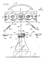
- Device 10 comprises two signal emitters 12a and 12b which emit signal beams 14a and 14b to two signal detectors 16a and 16b.
- the emitters and detectors operate in pairs such that signal detector 16a is positioned to detect the presence or absence of signal beam 14a from emitter 12a.
- detector 16b is positioned to detect the presence or absence of signal 14b emitted by emitter 12b.
- Device 10 may alternatively comprise more than two emitter-detector pairs. Each emitter may be aligned linearly with respect to its mated detector as shown in FIG. 1. Alternatively, the emitter-receiver pair may be arranged in a non-linear manner. This will be more fully described in an alternate embodiment of the present invention.
- Wires 17a, 17b, 17c and 17d operatively connect emitter 12a, emitter 12b, detector 16a and detector 16b respectively to a controller (not shown).
- the controller coordinates the timing and control of signal emission and detection. For example, the controller activates detectors 16a and 16b to detect signal beams 14a and 14b respectively only when the emitters 12a and 12b emit signal beams 14a and 14b respectively.
- the controller is programmable and may be programmed to generate a signal when detector 16a receives signal beam 14a from emitter 12a. Alternatively, the controller can be programmed to generate a signal when detector 16a does not receive signal beam 14a from emitter 12a.
- the controller may be programmed to define signal detection for emitter 12b and detector 16b in a similar manner.
- the signal emitted by emitters 12a and 12b may be any suitable signal capable of distinguishing between the narrow tolerances of a properly capped versus a miscapped bottle as is commonly known to those skilled in the art.
- the tolerance between a miscapped bottle and a properly capped bottle is on the order of tenths or hundredths of a millimeter. It has been found that the emission and corresponding detection of highly focused, narrow beams of light is capable of distinguishing between a proper cap and a miscapped bottle within these narrow parameters.
- light sources including, but not limited to, laser, x-ray, ultra-violet, visible, infrared or far red may be employed as the signal beam in accordance with the present invention.
- Favorable results have been achieved when utilizing the FT-100 Inspection Head manufactured by Industrial Dynamics International Corporation in accordance with the present invention.
- Conveyor 18 transports bottle 20 having bottle cap 22 thereon in the direction of motion indicated by arrow A.
- Correctly positioned cap 22a on bottle 20 defines a vertical cap axis B as shown in FIG. 1a.
- Correctly positioned cap 22a on bottle 20 also defines the correct cap height H relative to bottle 20.
- emitters 12a and 12b are located above and adjacent to conveyor 18 and are suitably mounted so that signal beams 14a and 14b respectively are normal to vertical axis B.
- emitters 12a and 12b are positioned to emit signal beams 14a and 14b at a proximate height H relative to bottle 20.
- bottle 20 is delivered to device 10 by conveyor 18 so that vertical axis B of bottle 20 is normal to signal beams 14a and 14b when emitted by emitters 12a and 12b.
- Emitters 12a and 12b may be positioned in any suitable configuration such that signal beams 14a and 14b are directed to different target locations of cap 20.
- emitters 12a and 12b may be located on the same side of conveyor 18.
- a single signal detector may be utilized.
- emitters 12a and 12b are coplanar and located on opposite sides of conveyor 18 thereby straddling conveyor 18.
- FIG. 1 illustrates this configuration wherein emitter 12a is on the same side of conveyor 18 as detector 16b.
- emitter 12b is on the same side of conveyor 18 as detector 16a. This arrangement results in the intersection of beams 14a and 14b and produces intersect angles 24a, 24b, 24c and 24d.
- Intersect angles 24a, 24b, 24c, 24d may range between about 45 degrees to about 135 degrees. It has been found that positioning emitters 12a and 12b so that angles 24a, 24b, 24c and 24d are each 90 degrees provides device 10 with the ability to detect substantially all high capped or cocked capped bottles regardless of the radial orientation of the bottle or the cap relative to the detection apparatus (typically reference to one of the bottle or cap includes the other, since typically once capped, even if incorrectly capped, the cap does not move relative to the bottle).
- Conveyor 18 transports bottle 20 having cap 22 to detection point C as shown in FIG.1.
- a sensor (not shown) operatively connected to the controller sends a signal to the controller that bottle 20 is located at detection point C.
- the controller then instructs emitters 12a and 12b to emit signal beams 14a and 14b respectively. Detection of signal beams 14a and 14b by signal detectors 16a and 16b respectively depends upon the placement of cap 22 upon bottle 20.
- FIG. 2 shows the beam detection profile for cap 22a when properly placed upon bottle 20.
- Emitters 12a and 12b direct signal beams 14a and 14b to traverse the plane defined by the top of properly placed cap 22a on bottle 20 without impingement.
- Signal detectors 16a and 16b thereby detect signal beams 14a and 14b respectively.
- the controller is programmed to interpret this detection profile as a properly capped bottle.
- FIG. 3 illustrates the beam detection profile for high cap 22b. Since emitters 12a and 12b are positioned to.deliver signal beams 14a and 14b respectively at height H, signal beams 14a and 14b are both prevented from traversing the plane defined by the top of a properly placed cap since cap 22b extends beyond height H. Signal detectors 16a and 16b therefore do not detect signal beams 14a and 14b.
- the controller is correspondingly programmed to interpret this detection profile as a high capped or miscapped bottle. As such, the controller may generate a signal indicating a miscapped bottle as desired.
- FIG. 4 depicts the beam detection profile for cocked cap 22c.
- Signal beam 14a traverses the plane defined by the plane of the top of a properly placed cap at height H. Signal beam 14a is thereby detected by signal detector 16a.
- Signal beam 14b is interrupted as a portion of cap 22c extends beyond height H. Signal detector 16b therefore does not detect signal beam 14b.
- the controller is programmed to interpret this detection profile as a miscapped bottle.
- the controller may be programmed to indicate these various detection beam profiles by any method commonly known to those skilled in the art.
- the controller may be operatively connected to a plurality of different colored lights to indicate a proper cap (i.e., green) a high cap (i.e., red) or a cocked cap (i.e., red).
- the controller may be operatively connected to a display screen that indicates the occurrence of a proper cap, a high cap or a cocked cap.
- the display screen may be positioned so that a person monitoring the bottling and capping production process may also monitor the occurrence of miscapped bottles.
- the controller is operatively connected to a discharge gate downstream of device 10 on conveyor 18.
- the controller Upon detection of high cap 22b or cocked cap 22c by device 10, the controller sends a signal to a discharge gate (not shown).
- the discharge gate directs the miscapped bottle to a discharge conveyor. The miscapped bottle is thereby automatically segregated or discharged from the bottling production line.
- FIGS. 5 and 5a illustrate an alternate embodiment of the present invention.
- the top edge of pilfer ring 26 of bottle 20 defines height N relative to bottle 20.
- height N can also be defined as the bottom of properly placed cap 22a relative to bottle 20 when bottle 20 does not have pilfer ring 26.
- Emitters 52a and 52b of detection device 50 are positioned so that signal beams 54a and 54b are at proximate height N relative to bottle 20 and normal to axis B. Furthermore, emitters 52a and 52b are positioned so that signal beams 54a and 54b traverse pilfer ring 26 at tangent points 62a and 62b respectively.
- Intersect angles 58a, 58b, 58c and 58d may range from about 30 degrees to about 150 degrees.
- emitters 52a and 52b are positioned so that tangent points 62a and 62b are 180 degrees apart from each other along the arc defined by the outermost circular perimeter defined by bottle cap 22.
- Conveyor 18 transports bottle 20 having cap 22 to detection point C as shown in FIG. 5.
- a sensor (not shown) operatively connected to the controller sends a signal to the controller that bottle 20 is located at detection point C.
- the controller then signals emitters 52a and 52b to emit signal beams 54a and 54b respectively. Detection of signal beams 54a and 54b by signal detectors 56a and 56b respectively depends upon the placement of cap 22 upon bottle 20.
- FIG. 6 shows the beam detection profile for cap 22a when properly placed upon bottle 20.
- Emitters 52a and 52b direct signal beams 54a and 54b (shown partially in phantom) to tangent points 62a and 62b respectively just above pilfer ring 26. Since the bottom of cap 22a abuts pilfer ring 26, cap 22a prevents signal detectors 56a and 56b from detecting signal beams 54a and 54b respectively.
- the controller is programmed to interpret this absence of detection as a properly capped bottle. Hence, the controller in this situation generates no miscapped bottle indicia.
- a signal beam detection threshold may be programmed into the controller. This threshold establishes a minimal signal that constitutes a valid detection. Thus, some degree of signal may be detected by detectors 56a and 56b yet still be interpreted by the controller as the absence of detection thereby identifying a properly placed cap.
- FIG. 7 illustrates the beam detection profile for high cap 22b.
- signal beams 54a and 54b traverse tangent points 62a and 62b respectively and are detected by signal detectors 56a and 56b respectively.
- the controller is programmed to generate a signal indicating a high capped or miscapped bottle.
- FIG. 8 depicts the beam detection profile for cocked cap 22c.
- a portion of cocked cap 22c abuts pilfer ring 26 at tangent point 62a and blocks signal beam 54a (shown in phantom) from being detected by signal detector 56a.
- the bottom of cocked cap 22c is above height N at tangent point 62b. This allows signal beam 54b to traverse tangent point 62b and be detected by signal detector 56b. With this detection, the controller is programmed to generate a signal indicating a cocked cap or an otherwise miscapped bottle.
- FIGS. 9 and 9a depict an alternate embodiment of the present invention, wherein bottle cap 70 comprises reflective band 72.
- Reflective band 72 extends circumferentially around a portion of the axial surface of cap 70.
- reflective band 72 also defines the height of a properly placed cap S relative to bottle 20 as shown in FIG. 9a.
- Reflective band 72 may be made of any suitably adapted reflective material. Reflective band 72 may be integral to and constructed of the same material as cap 70. Alternatively, reflective band 72 may comprise a reflective material that is affixed to bottle cap 70 in any manner commonly known to the skilled artisan. This material may include, but is not limited to, plastic, metal, glass or any combination thereof. Preferably, bottle cap 70 is a resilient polymer plastic with reflective band 72 integral thereto and having a smooth reflective surface.
- Miscapped bottle detection device 80 comprises emitter 82a and 82b which emit signal beams 84a and 84b respectively.
- Emitters 82a and 82b are positioned so that signal beams 84a and 84b are at proximate height S relative to bottle 20 and normal to vertical bottle axis B as shown in FIG. 9a.
- Emitters 82a and 82b are located on the same side of conveyor 18.
- a single signal detector 86 is located on the opposing side of conveyor 18 and is positioned to detect the absence or presence reflected beams 84a and 84b.
- Conveyor 18 transports bottle 20 having cap 70 to detection point C as shown in FIG. 9.
- a sensor (not shown) operatively connected to the controller sends a signal to the controller that bottle 20 is located at detection point C.
- the controller then instructs emitters 82a and 82b to emit signal beams 84a and 84b respectively.
- Emitters 82a and 82b are positioned so that signal beams 84a and 84b respectively contact the axial surface of bottle cap 70 at different target points 90a and 90b respectively.
- the radial arc separating target points 90a and 90b on cap 70 is preferably between about 45 degrees to about 180 degrees.
- FIG.1 illustrates the most preferred arrangement wherein target points 90a and 90b are 180 degrees apart from each other along the radial arc of cap 70. Detection of signal beams 84a and 84b by signal detector 86 depends upon the placement of cap 70 upon bottle 20.
- FIG. 10 illustrates the beam detection profile for a properly placed cap 70a on bottle 20.
- Emitters 82a and 82b direct signal beams 84a and 84b respectively to contact the side of cap 70a at target points 90a and 90b respectively. Both target points 90a and 90b contact bottle cap 70a on reflective band 72. Signal beams 84a and 84b are thereby reflected to detector 86 wherein detection occurs.
- Detector 86 is preferably curved to more readily detect signal beams 84a and 84b.
- a curved detector 86 also allows more flexibility for the placement of emitters 82a and 82b.
- signal beam 82a is at a different frequency and/or wavelength than 82b to avoid interference.
- detector 86 may be any signal detector commonly known to those skilled in the art that can detect multiple signals at different frequencies and/or wavelengths.
- the controller is programmed to interpret this detection profile as a properly capped bottle. A corresponding signal indicating a properly capped bottle may be generated as desired.
- FIG. 11 shows the beam detection profile for high cap 70b on bottle 20.
- Reflective band 72 is above height S.
- Signal beams 84a and 84b contact bottle cap 70b at target points 90a and 90b respectively at non-reflective regions of bottle cap 70b.
- signal beams 84a and 84b are either absorbed or dispersed by cap 70b.
- Signal beams 84a and 84b are not reflected by reflective band 72 and no signal detection occurs by detector 86.
- the controller is programmed to interpret this absence of detection as a miscapped bottle.
- a signal may be generated to indicate a miscapped bottle.
- FIG. 12 depicts the beam detection profile for cocked cap 70c.
- a portion of reflective band 72 is at height S.
- target point 90a for signal beam 84a occurs on reflective band 72.
- Signal beam 84a is thereby reflected to detector 86 for detection.
- a portion of reflective band 72 is above height S.
- Contact point 90b for signal beam 84b thereby contacts cocked cap 70c at a non-reflective portion.
- Signal beam 84b is either dispersed or absorbed by the non-reflective portion of cocked cap 70c and not detected by detector 86.
- the controller is programmed to interpret this detection profile as a miscapped bottle.
- a signal may be generated to indicate a miscapped bottle.
- FIG. 13 depicts the beam detection profile for low cap 70d.
- Reflective band 72 on low cap 70d is below height S.
- target points 90a and 90b for signal beams 84a and 84b respectively occur at non-reflective regions of low cap 70d.
- Signal beams 84a and 84b are either dispersed or absorbed by these non-reflective regions of low cap 70d.
- Detector 86 therefore detects neither signal beam 84a nor signal beam 84b.
- the controller is programmed to interpret this detection profile as a miscapped bottle.
- a corresponding signal to indicate a miscapped bottle may be generated as desired.
- band 72 could be nonreflective or dispersive and adjacent cap regions reflective, in which case the detection of a reflected signal would be indicative of an improperly positioned cap and the detection of a signal indicative of an incorrectly positioned cap.
- FIGS. 14 and 14a depict an alternate embodiment of miscapped bottle detection device 100 wherein emitter 102a, signal beam 104a and signal detector 106a are all positioned at relative height H. Emitter 102b, signal beam 104b and signal detector 106b are also positioned at relative height N. Emitter 102a is nonplanar in relation to emitter 102b. Emitters 102a and 102b are normal to axis B and are preferably on opposing sides of conveyor 18. Emitters 102a and 102b are further positioned so that signal beams 104a and 104b would intersect if in the same plane. Preferably, the angles between skewed beams 104a and 104b is 90 degrees.
- signal beam 104a traverses the plane defined by the top of properly placed cap 22a.
- signal beam 104b traverses the top of pilfer ring 26 at tangent point 108. Detection of signal beams 104a and 104b by signal detectors 106a and 106b respectively depends upon the placement of cap 22 upon bottle 20.
- FIG. 15 shows the beam detection profile for properly placed cap 22a upon bottle 20.
- Signal beam 104a traverses the plane defined by the top of cap 22a at height H.
- Signal beam 104a is subsequently detected by detector 106a.
- Signal beam 104b (shown in phantom) is blocked as the bottom of cap 22a abuts pilfer ring 26 (at height N) at tangent point 108.
- the controller is programmed to interpret this detection profile as a properly capped bottle.
- FIG. 16 illustrates the beam detection profile for high cap 22b upon bottle 20.
- High cap 22b extends beyond height H thereby blocking signal beam 104a from detection by detector 106a.
- the bottom of high cap 22b is above height N and signal beam 104b traverses tangent point 108 and is detected by detector 106b.
- the controller is programmed to interpret this detection profile as a miscapped bottle.
- FIGS. 17 and 17a show two beam detection profiles for cocked cap 22c.
- FIG. 17 depicts cocked cap 22c riding bottle 20 so that signal beam 104a traverses the top of cap 22c and is readily detected by detector 106a.
- Signal beam 104b traverses bottle 20 at tangent point 108 and is detected by detector 106b.
- the controller is programmed to interpret this detection profile as a cocked capped or miscapped bottle.
- FIG. 17a depicts a second permutation for cocked cap 22c.
- Signal beam 104a is blocked by cocked cap 22c preventing detection from detector 106a.
- the bottom of cocked cap 22c abuts pilfer ring 26 at tangent point 108 thereby blocking signal beam 104b (shown partially in phantom) from detection by detector 106b.
- the controller is programmed to interpret this detection profile as a cocked cap or miscapped bottle.
- the invention provides apparatus and methods for detecting misaligned or incorrectly positioned bottle caps in a bottle line process.
Landscapes
- Engineering & Computer Science (AREA)
- Mechanical Engineering (AREA)
- Sealing Of Jars (AREA)
- Filling Of Jars Or Cans And Processes For Cleaning And Sealing Jars (AREA)
- Closures For Containers (AREA)
Applications Claiming Priority (2)
| Application Number | Priority Date | Filing Date | Title |
|---|---|---|---|
| US946373 | 2001-09-04 | ||
| US09/946,373 US6654117B1 (en) | 2001-09-04 | 2001-09-04 | Bottle cap sensor apparatus and method |
Publications (2)
| Publication Number | Publication Date |
|---|---|
| EP1293473A2 true EP1293473A2 (de) | 2003-03-19 |
| EP1293473A3 EP1293473A3 (de) | 2003-12-17 |
Family
ID=25484378
Family Applications (1)
| Application Number | Title | Priority Date | Filing Date |
|---|---|---|---|
| EP02256134A Withdrawn EP1293473A3 (de) | 2001-09-04 | 2002-09-04 | Verfahren und Vorrichtung zur Kontrolle des Verschliessvorgangs für Flaschen |
Country Status (5)
| Country | Link |
|---|---|
| US (1) | US6654117B1 (de) |
| EP (1) | EP1293473A3 (de) |
| BR (1) | BR0203621A (de) |
| CA (1) | CA2401127A1 (de) |
| MX (1) | MXPA02008655A (de) |
Cited By (6)
| Publication number | Priority date | Publication date | Assignee | Title |
|---|---|---|---|---|
| WO2010075918A1 (de) * | 2008-12-17 | 2010-07-08 | Khs Ag | Verfahren sowie inspektionsvorrichtung zum überprüfen von behältern |
| DE102009042109A1 (de) * | 2009-09-11 | 2011-04-07 | Closure Systems International Deutschland Gmbh | Verschließmaschine und Verfahren zum Verschließen von Behältern |
| DE102012003809A1 (de) * | 2012-02-27 | 2013-08-29 | Heuft Systemtechnik Gmbh | Verfahren und Vorrichtung zum berührungslosen Prüfen des zum Öffnen eines Kunststoff-Schraubverschlusses erforderlichen Drehmoments |
| EP2635519A4 (de) * | 2010-11-01 | 2015-05-20 | Make All Corp | Verfahren zur erkennung erhöhter phiolenstopfen |
| DE102015211317A1 (de) * | 2015-06-19 | 2016-12-22 | Krones Ag | Inspektionsverfahren und -vorrichtung zur Verschlusskontrolle von Behältern |
| DE102017200913A1 (de) | 2017-01-20 | 2018-07-26 | Krones Ag | Vorrichtung und Verfahren zur Verschlusskontrolle für Verschlüsse auf Behältern |
Families Citing this family (13)
| Publication number | Priority date | Publication date | Assignee | Title |
|---|---|---|---|---|
| US9150399B2 (en) * | 2009-05-01 | 2015-10-06 | Richard D. Michelli | Portable and automatic bottle filling/capping apparatus and methods |
| DE102009041212A1 (de) * | 2009-09-11 | 2011-04-07 | Krones Ag | Vorrichtung und Verfahren zum Kontrollieren von Gefäßverschlüssen |
| JP5372731B2 (ja) * | 2009-12-28 | 2013-12-18 | 株式会社日立ハイテクノロジーズ | 分析装置および分析装置に用いる検知方法 |
| CN102095733B (zh) * | 2011-03-02 | 2012-08-08 | 上海大学 | 一种基于机器视觉对瓶盖表面瑕疵的智能检测方法 |
| CN102590223A (zh) * | 2012-03-26 | 2012-07-18 | 楚天科技股份有限公司 | 一种瓶体加塞质量检测装置 |
| NL2010994C2 (en) * | 2013-06-17 | 2014-12-18 | Fuji Seal Europe Bv | Container sleeving method and device. |
| DE102014221029B4 (de) | 2014-10-16 | 2023-03-30 | Syntegon Technology Gmbh | Überwachungseinheit zum Überwachen von Objekten für pharmazeutische Anwendungen, insbesondere Stopfen für Behältnisse |
| EP3413055B1 (de) * | 2017-06-09 | 2021-10-06 | Roche Diagnostics GmbH | Verfahren zur erkennung eines abdeckungszustands und laborprobenverteilungssystem |
| JP6912367B2 (ja) * | 2017-12-15 | 2021-08-04 | アサヒ飲料株式会社 | キャップ浮き検査方法及びキャップ浮き検査装置 |
| JP7296193B2 (ja) * | 2018-04-03 | 2023-06-22 | サッポロビール株式会社 | キャップ不良検査装置、及び、キャップ不良検査方法 |
| US11230400B2 (en) * | 2018-05-07 | 2022-01-25 | V Anrx Pharmasystems Inc. | Method, device and system for filling pharmaceutical containers |
| US11305975B2 (en) * | 2018-12-19 | 2022-04-19 | Silgan White Cap LLC | Dual laser closure scan and method of using the same |
| CN114715448B (zh) * | 2022-06-09 | 2022-08-26 | 北京先通国际医药科技股份有限公司 | 放射性药物的分装系统及分装方法、及其用途 |
Citations (5)
| Publication number | Priority date | Publication date | Assignee | Title |
|---|---|---|---|---|
| US2689647A (en) * | 1952-09-02 | 1954-09-21 | Purex Corp Ltd | Bottle cap position detector |
| GB926195A (en) * | 1960-12-14 | 1963-05-15 | Bush And Rank Cintel Ltd | Apparatus for detecting the presence of closures upon containers |
| DE19540545A1 (de) * | 1995-10-31 | 1997-05-15 | Kronseder Maschf Krones | Verfahren und Vorrichtung zum Überprüfen des Sitzes von Verschlußkappen auf Gefäßen |
| US6104482A (en) * | 1999-12-02 | 2000-08-15 | Owens-Brockway Glass Container Inc. | Container finish check detection |
| US6237418B1 (en) * | 1999-06-21 | 2001-05-29 | Benthos, Inc. | Method and apparatus for detecting misapplied caps on containers |
Family Cites Families (17)
| Publication number | Priority date | Publication date | Assignee | Title |
|---|---|---|---|---|
| US2689646A (en) | 1951-08-09 | 1954-09-21 | Allen E Dilliard | Fluid flotation separator and method for separating pulverized materials |
| US3469689A (en) | 1966-04-28 | 1969-09-30 | Bron Electronics Inc | Improperly-sealed-container rejector |
| US4355724A (en) | 1980-06-18 | 1982-10-26 | Tropicana Products, Inc. | Apparatus for sensing depressions in top panels of containers |
| AU553069B2 (en) | 1981-07-17 | 1986-07-03 | W.R. Grace & Co.-Conn. | Radial scan, pulsed light article inspection ccv system 0 |
| US4511044A (en) | 1982-02-24 | 1985-04-16 | The West Company | Seal force monitor apparatus, system, and method for in-process determination of integrity of sealed containers |
| US4691496A (en) | 1983-01-31 | 1987-09-08 | Peco Controls Corporation | Filler line monitoring system |
| JPS61232195A (ja) | 1985-03-29 | 1986-10-16 | サッポロビール株式会社 | 壜口のキヤツプ検査装置 |
| US4772128A (en) | 1986-03-25 | 1988-09-20 | Dolan-Jenner Industries, Inc. | Fiber optic imaging system for on-line monitoring |
| SE457719B (sv) | 1987-05-26 | 1989-01-23 | Wicanders Kapsyl Ab | Anordning foer att applicera kapsyler paa behaallare, innefattande en primaer och en sekundaer kapsylpaalaeggare |
| US4872300A (en) | 1988-08-26 | 1989-10-10 | Frankandale Corporation | Cap detector for bottling system with high speed gate mechanism |
| US5214953A (en) | 1990-04-06 | 1993-06-01 | Servi-Tech, Inc. | Multi-use fill height test devices |
| US5010760A (en) | 1990-04-06 | 1991-04-30 | Servi-Tech, Inc. | Multi-use fill height test devices |
| US5489987A (en) | 1994-04-07 | 1996-02-06 | Owens-Brockway Glass Container Inc. | Container sealing surface inspection |
| US5591462A (en) | 1994-11-21 | 1997-01-07 | Pressco Technology, Inc. | Bottle inspection along molder transport path |
| US5749201A (en) | 1996-08-19 | 1998-05-12 | Cochrane; Benjamin | Laser bonded tamper proof press-on cap and seal |
| US5714998A (en) | 1997-01-13 | 1998-02-03 | Sony Corporation | Video inspection system for conveyors |
| US6473170B2 (en) * | 2001-01-19 | 2002-10-29 | White Cap, Inc. | Linear optical sensor for a closure |
-
2001
- 2001-09-04 US US09/946,373 patent/US6654117B1/en not_active Expired - Lifetime
-
2002
- 2002-09-03 CA CA002401127A patent/CA2401127A1/en not_active Abandoned
- 2002-09-03 BR BR0203621-5A patent/BR0203621A/pt not_active IP Right Cessation
- 2002-09-04 MX MXPA02008655A patent/MXPA02008655A/es active IP Right Grant
- 2002-09-04 EP EP02256134A patent/EP1293473A3/de not_active Withdrawn
Patent Citations (5)
| Publication number | Priority date | Publication date | Assignee | Title |
|---|---|---|---|---|
| US2689647A (en) * | 1952-09-02 | 1954-09-21 | Purex Corp Ltd | Bottle cap position detector |
| GB926195A (en) * | 1960-12-14 | 1963-05-15 | Bush And Rank Cintel Ltd | Apparatus for detecting the presence of closures upon containers |
| DE19540545A1 (de) * | 1995-10-31 | 1997-05-15 | Kronseder Maschf Krones | Verfahren und Vorrichtung zum Überprüfen des Sitzes von Verschlußkappen auf Gefäßen |
| US6237418B1 (en) * | 1999-06-21 | 2001-05-29 | Benthos, Inc. | Method and apparatus for detecting misapplied caps on containers |
| US6104482A (en) * | 1999-12-02 | 2000-08-15 | Owens-Brockway Glass Container Inc. | Container finish check detection |
Cited By (13)
| Publication number | Priority date | Publication date | Assignee | Title |
|---|---|---|---|---|
| CN102186764B (zh) * | 2008-12-17 | 2014-02-12 | Khs有限责任公司 | 用于测试容器的方法与检测装置 |
| CN102186764A (zh) * | 2008-12-17 | 2011-09-14 | Khs有限责任公司 | 用于测试容器的方法与检测装置 |
| RU2478560C2 (ru) * | 2008-12-17 | 2013-04-10 | Кхс Гмбх | Способ и бракеражное устройство для контроля сосудов бутылок |
| WO2010075918A1 (de) * | 2008-12-17 | 2010-07-08 | Khs Ag | Verfahren sowie inspektionsvorrichtung zum überprüfen von behältern |
| US8937656B2 (en) | 2008-12-17 | 2015-01-20 | Khs Gmbh | Method and inspection device for testing containers |
| DE102009042109A1 (de) * | 2009-09-11 | 2011-04-07 | Closure Systems International Deutschland Gmbh | Verschließmaschine und Verfahren zum Verschließen von Behältern |
| EP2635519A4 (de) * | 2010-11-01 | 2015-05-20 | Make All Corp | Verfahren zur erkennung erhöhter phiolenstopfen |
| DE102012003809A1 (de) * | 2012-02-27 | 2013-08-29 | Heuft Systemtechnik Gmbh | Verfahren und Vorrichtung zum berührungslosen Prüfen des zum Öffnen eines Kunststoff-Schraubverschlusses erforderlichen Drehmoments |
| WO2013127719A1 (de) | 2012-02-27 | 2013-09-06 | Heuft Systemtechnik Gmbh | Verfahren und vorrichtung zum berührungslosen prüfen eines schraubverschlussdrehmoments |
| US9569833B2 (en) | 2012-02-27 | 2017-02-14 | Heuft Systemtechnik Gmbh | Method and apparatus for checking a screw closure torque without contact |
| DE102015211317A1 (de) * | 2015-06-19 | 2016-12-22 | Krones Ag | Inspektionsverfahren und -vorrichtung zur Verschlusskontrolle von Behältern |
| DE102015211317B4 (de) * | 2015-06-19 | 2021-04-01 | Krones Ag | Inspektionsverfahren und -vorrichtung zur Verschlusskontrolle von Behältern |
| DE102017200913A1 (de) | 2017-01-20 | 2018-07-26 | Krones Ag | Vorrichtung und Verfahren zur Verschlusskontrolle für Verschlüsse auf Behältern |
Also Published As
| Publication number | Publication date |
|---|---|
| US6654117B1 (en) | 2003-11-25 |
| MXPA02008655A (es) | 2004-07-16 |
| BR0203621A (pt) | 2003-06-03 |
| EP1293473A3 (de) | 2003-12-17 |
| CA2401127A1 (en) | 2003-03-04 |
Similar Documents
| Publication | Publication Date | Title |
|---|---|---|
| EP1293473A2 (de) | Verfahren und Vorrichtung zur Kontrolle des Verschliessvorgangs für Flaschen | |
| US6473170B2 (en) | Linear optical sensor for a closure | |
| US9434591B2 (en) | Method for the monitoring, control and optimization of filling equipment for foods and beverages, such as, for beverage bottles | |
| US7832181B2 (en) | Detection system | |
| US20130278927A1 (en) | Raised Vial Stopper Detection System | |
| JP5730893B2 (ja) | 切削システム及び切削方法 | |
| JP5052403B2 (ja) | ガラス容器の検査機 | |
| EP0676633B1 (de) | Prüfung der Dichtfläche eines Behälters | |
| EP3605010B1 (de) | Verfahren und vorrichtung zur detektion von defekten im verschluss von verkapselten phiolen | |
| US4580045A (en) | Apparatus for the inspection of glassware for leaners and chokes | |
| US6237418B1 (en) | Method and apparatus for detecting misapplied caps on containers | |
| JP2017219504A (ja) | 壜検査装置 | |
| US20030231317A1 (en) | System and device for detecting and separating out of position objects during manufacturing process | |
| EP0101246B1 (de) | Gerät zum Überprüfen von Glasbehältern auf Neigungs- und Verengungsfehler | |
| CN107894428A (zh) | 一种饮料瓶封盖质量检测传感器 | |
| US3700101A (en) | Container inspection apparatus | |
| GB2042164A (en) | Testing for container defects | |
| JPH06201612A (ja) | ボトルシールの外観検査方法及び装置 | |
| JP5166340B2 (ja) | 容器蓋のブリッジ切れ角度測定装置及びその角度測定方法 | |
| WO2019126907A1 (zh) | 一种饮料瓶封盖质量检测传感器 | |
| CN211593104U (zh) | 包装瓶热塑膜的检测装置 | |
| JPH09226728A (ja) | 缶内圧検査装置 | |
| JPH07128016A (ja) | 2物体の重畳状態の検出方法および装置 | |
| JP2007057431A (ja) | 樹脂製瓶体の疵検査方法及び疵検査装置 | |
| JPH0331221B2 (de) |
Legal Events
| Date | Code | Title | Description |
|---|---|---|---|
| PUAI | Public reference made under article 153(3) epc to a published international application that has entered the european phase |
Free format text: ORIGINAL CODE: 0009012 |
|
| AK | Designated contracting states |
Kind code of ref document: A2 Designated state(s): AT BE BG CH CY CZ DE DK EE ES FI FR GB GR IE IT LI LU MC NL PT SE SK TR Designated state(s): AT BE BG CH CY CZ DE DK EE ES FI FR GB GR IE IT LI LU MC NL PT SE SK TR |
|
| AX | Request for extension of the european patent |
Extension state: AL LT LV MK RO SI |
|
| PUAL | Search report despatched |
Free format text: ORIGINAL CODE: 0009013 |
|
| AK | Designated contracting states |
Kind code of ref document: A3 Designated state(s): AT BE BG CH CY CZ DE DK EE ES FI FR GB GR IE IT LI LU MC NL PT SE SK TR |
|
| AX | Request for extension of the european patent |
Extension state: AL LT LV MK RO SI |
|
| RIC1 | Information provided on ipc code assigned before grant |
Ipc: 7G 01N 21/90 B Ipc: 7B 67B 3/26 A |
|
| 17P | Request for examination filed |
Effective date: 20040616 |
|
| AKX | Designation fees paid |
Designated state(s): AT BE BG CH CY CZ DE DK EE ES FI FR GB GR IE IT LI LU MC NL PT SE SK TR |
|
| AXX | Extension fees paid |
Extension state: SI Payment date: 20040616 Extension state: RO Payment date: 20040616 Extension state: MK Payment date: 20040616 Extension state: LV Payment date: 20040616 Extension state: LT Payment date: 20040616 Extension state: AL Payment date: 20040616 |
|
| STAA | Information on the status of an ep patent application or granted ep patent |
Free format text: STATUS: THE APPLICATION IS DEEMED TO BE WITHDRAWN |
|
| 18D | Application deemed to be withdrawn |
Effective date: 20090401 |