EP1292176A2 - Vorrichtung zum Erzeugen eines Aktivgasstrahls - Google Patents
Vorrichtung zum Erzeugen eines Aktivgasstrahls Download PDFInfo
- Publication number
- EP1292176A2 EP1292176A2 EP02019754A EP02019754A EP1292176A2 EP 1292176 A2 EP1292176 A2 EP 1292176A2 EP 02019754 A EP02019754 A EP 02019754A EP 02019754 A EP02019754 A EP 02019754A EP 1292176 A2 EP1292176 A2 EP 1292176A2
- Authority
- EP
- European Patent Office
- Prior art keywords
- discharge chamber
- channel
- discharge
- gas
- process gas
- Prior art date
- Legal status (The legal status is an assumption and is not a legal conclusion. Google has not performed a legal analysis and makes no representation as to the accuracy of the status listed.)
- Granted
Links
Images


Classifications
-
- H—ELECTRICITY
- H05—ELECTRIC TECHNIQUES NOT OTHERWISE PROVIDED FOR
- H05H—PLASMA TECHNIQUE; PRODUCTION OF ACCELERATED ELECTRICALLY-CHARGED PARTICLES OR OF NEUTRONS; PRODUCTION OR ACCELERATION OF NEUTRAL MOLECULAR OR ATOMIC BEAMS
- H05H1/00—Generating plasma; Handling plasma
- H05H1/24—Generating plasma
- H05H1/26—Plasma torches
- H05H1/30—Plasma torches using applied electromagnetic fields, e.g. high frequency or microwave energy
-
- H—ELECTRICITY
- H05—ELECTRIC TECHNIQUES NOT OTHERWISE PROVIDED FOR
- H05H—PLASMA TECHNIQUE; PRODUCTION OF ACCELERATED ELECTRICALLY-CHARGED PARTICLES OR OF NEUTRONS; PRODUCTION OR ACCELERATION OF NEUTRAL MOLECULAR OR ATOMIC BEAMS
- H05H1/00—Generating plasma; Handling plasma
- H05H1/24—Generating plasma
- H05H1/26—Plasma torches
- H05H1/32—Plasma torches using an arc
- H05H1/34—Details, e.g. electrodes, nozzles
- H05H1/3484—Convergent-divergent nozzles
Definitions
- the invention relates to a device for generating a chemically active Jet (hereinafter referred to as active gas jet) by means of an electrically generated Plasma in a process gas used.
- active gas jet a chemically active Jet
- the invention is particularly suitable for the treatment of surfaces, e.g. for pretreatment and cleaning of Surfaces before gluing, coating or painting, for coating, Hydrophilizing, removing electrical charges or sterilizing and for Acceleration of chemical reactions.
- the gas to be activated is passed directly through an electrical discharge zone.
- the discharge zone is formed in a tube by means of an electric field, with either electrodes being arranged laterally inside the tube in the direction of flow of the gas, or a discharge chamber made of insulating material without electrodes installed in a waveguide.
- This solution has the disadvantage already mentioned above that, at a high speed of the activated gas flow, there is a high probability of electromagnetic fields and the electrical discharge zone itself emerging from the discharge chamber in the direction of the active gas jet, since there is no shielding ring electrode at the end of the discharge chamber.
- the arrangement described in EP 0 305 241 A1 prevents the operator from being endangered by a separate, closed processing chamber in which the surface treatment of the material takes place.
- the invention has for its object a new way to Generation of a chemically active jet (active gas jet) by means of a electrical discharge generated plasma in a process gas used find at which at an increased process gas speed the active gas jet on the processing surface develops a high chemical activity and already on Output of the device is electrically neutral, so that it is not a hazard to Operating personnel, environment and processed surface.
- active gas jet active gas jet
- the object in a device for generating a chemically active jet (active gas jet) by means of an electrical discharge generated plasma in a process gas used with an essentially cylindrical discharge chamber, through which a process gas flows and in to activate the process gas, plasma generation due to electrical Gas discharge is provided, a gas inlet for the continuous supply of the Process gas into the discharge chamber and an outlet opening for alignment of the active gas jet onto a surface to be processed, characterized in that that the discharge chamber has a tapered end to increase the Has velocity of the active gas jet, the tapered end of the Discharge chamber a limiting channel to prevent the spread of the Discharge zone in the free space for the surface to be processed is arranged downstream, the limiting channel being essentially cylindrical is trained and grounded and its length is greater than the factor 5-10 Cross section is.
- An arc discharge is advantageously provided for activating the process gas, the discharge chamber having a central electrode and a hollow electrode which covers the inner wall of the discharge chamber at least in the region of the conically tapered end in a flat and symmetrical manner.
- the limiting channel preferably adjoins the hollow electrode directly.
- the central electrode is expediently rod-shaped and is arranged in the gas inlet region along the axis of symmetry of the discharge chamber.
- the central electrode can advantageously be used to increase the power of the active gas jet by means of enlarged electrode areas, which have the shape of a cylinder cap, which includes a cylinder jacket surface of low height and a cover area, and whose opening is aligned coaxially with the axis of the discharge chamber and is arranged above the gas inlet of the discharge chamber.
- the discharge chamber in an induction field generated at high frequency (radio frequency) in order to activate the process gas.
- the discharge chamber (1) is provided with two electrodes which are arranged along the wall of the discharge chamber in the flow direction of the process gas and are operated at radio frequency.
- the high-frequency excitation for activating the process gas can also advantageously be achieved by generating an induction field by arranging the discharge chamber in a coil operated at radio frequency.
- Another possibility for activating the process gas without contamination of the active gas by electrode material is that the discharge chamber is arranged in a waveguide connected to a microwave source.
- a beam shaping device is expediently arranged downstream of the limiting channel. It can be advantageous here that branched nozzles for processing individual partial areas or depressions of the surface to be processed are connected to the outlet of the boundary channel.
- the beam-shaping device is expediently adapted to the shape of the surface to be processed by guide plates, the distance between the surface and the beam-shaping device being kept in a defined small area, so that the effectively treated surface comprises a larger area.
- jet-shaping devices which incorporate two or more devices according to the invention for generating the active gas jet into a processing channel, wherein several surfaces of a workpiece to be treated simultaneously or surfaces of extruded profiles with any cross section can be processed on all sides in the processing channel with continuous material flow.
- a feed tube for introducing additives is preferably arranged axially in the discharge chamber, which ends shortly before the discharge chamber exits, an influence of the additives on the discharge characteristic and contamination of the Discharge chamber (1) is avoided by the additives or their reaction products.
- the limiting channel comprises a plurality of individual channels in order to reduce the gas dynamic resistance and the residence time of the active gas in the limiting channel, the individual channels being arranged evenly distributed around a central channel.
- the supply of additives is particularly favorable if the limiting channel with a plurality of individual channels has a central inlet channel for the additives, the inlet channel being arranged axially in the center of a ring of individual channels through which active gas flows, since there is a premature reaction or disintegration of the additives and contamination of the discharge chamber by the additives can be avoided.
- the additives in the area of the boundary channel can advantageously be introduced as gases, liquids in the form of aerosols or solids in the form of fine particles.
- the hollow electrode, the limiting channel and the beam-shaping device are manufactured as a uniform rotating body with very good electrical conductivity
- the central electrode is surrounded coaxially by an insulator tube and inserted into the discharge chamber formed by the hollow electrode
- the gas inlet into the discharge chamber is initially one cylindrical distribution chamber, wherein tangential flow channels are provided for the process gas from the distribution chamber to the discharge chamber, so that as a result of a spiral gas flow from the distribution chamber into the discharge chamber, arc discharges between the central electrode and the hollow electrode are fixed to an end of the central electrode protruding from the insulator tube. This largely prevents erosion of the insulator tube.
- Tangential flow channels can advantageously also be guided into a cylindrical annular chamber between the rod-shaped central electrode and the inner surface of the insulator tube, so that the central electrode is cooled directly by a portion of the process gas and exit points of arc discharges are essentially restricted to non-cylindrical surfaces of the central electrode.
- the insulator tube is expediently towered over by the central electrode by a length of up to twice the diameter of the central electrode. If the additional process gas supply within the insulator tube is used, the end of the central electrode can be shortened and in extreme cases ends with the end of the insulator tube.
- the limiting channel is preferably narrowed conically in the direction of gas flow and has an average ratio of channel diameter to channel length of 1: 8.
- the limiting channel is advantageously followed by a beam-shaping device with a bell-shaped widened output, so that the working width of the active gas jet is increased.
- the basic idea of the invention is based on the fact that, in the known devices of the prior art with plasma-induced active gas jet, either the activity of the gas jet is too low or the active gas jet still has a dangerously high electrical potential when it emerges into the processing space, which leads to a risk to the operating personnel , According to the invention, these mutually influencing problems are eliminated by passing the process gas through three zones in succession.
- the process gas (in the discharge space) is activated and accelerated, then the speed-related spreading of the discharge zone out of the discharge space into the active gas jet is intercepted (limited) in a narrow, earthed limiting channel and finally an electrically neutral, chemically active active gas jet by beam-shaping devices according to the desired application (Cleaning, coating, activation, etc.) is formed.
- the device according to the invention can be combined with all known methods of plasma-induced activation of process gases in which a corona, glow or arc discharge zone (using a direct, alternating or pulse current) or a high-frequency discharge zone generated in an alternating electromagnetic field (with excitation frequencies up to the Microwave range).
- the effectiveness of the limiting channel depends essentially on the fact that it has a smaller diameter in relation to the discharge chamber. Therefore, the discharge chamber is tapered in the flow direction of the process gas, so that with a large ratio of the cross section of the discharge chamber to the cross section of the limiting channel, the speed of the active gas jet increases significantly, which means that the time required for the chemically active particles of the active gas jet to travel the distance from the discharge chamber covered to the application site is greatly reduced. As a result of the reduction in time, there are fewer recombinations of active particles (reduced activity loss of the active gas jet) and this leads to an increase in the effectiveness of the active gas jet on the surface to be processed.
- the active gas jet is guided through a narrow, earthed channel at the exit of the discharge zone.
- the boundary channel is dimensioned such that a discharge arc entering it has a potential whose size at the entrance to the boundary channel is still too small for a breakthrough to the channel wall.
- the boundary channel must therefore have a minimum length in accordance with the other conditions of plasma generation, which ensures that the aforementioned bulges of the discharge zone into the free space cannot occur. This happens with a ratio of the cross section to the channel length of 1: 5 to 1:10.
- the device according to the invention allows the generation of an electrical neutral, chemically active jet, with increased process gas velocity the active gas jet on the surface to be processed has a high chemical Activity unfolds and is electrically neutral at the exit of the device, so that he posed no danger to operating personnel, the environment and Represents surface.
- the basic structure of the device for generating an active gas jet according to FIG. 1 consists of a discharge chamber 2 through which a process gas 1 flows, in which the process gas 1 is activated in the form of an electrical discharge generated by a strong field 3, an essentially cylindrical limiting channel 4 and a beam shaping device 5 for the active gas jet 6 intended for material processing in free space.
- the discharge chamber 2 has, in the flow direction of the process gas 1, a conically tapered end 21 (ie a nozzle-like constricted shape) which serves to increase the flow rate of the process gas 1 during its activation in the discharge chamber 2. With this increase in gas velocity, the time required to reach a surface 7 to be machined (only shown in FIGS.
- the limiting channel 4 is dimensioned such that the part of the discharge zone 22 entering it reaches such a potential, the size of which at the entry into the limiting channel 4 is still too small for a breakthrough to the channel wall, but increases so much with increasing path length in the limiting channel 4, until there is a breakthrough to the earthed wall of the limiting channel 4. Furthermore, the limiting channel 4 must have a minimum length in accordance with the other conditions of the plasma generation required to activate the process gas 1, which ensures that the aforementioned bulges 24 of the discharge zone 22 cannot occur in the free space. This is usually achieved with a ratio of the channel cross-section to the channel length of 1: 5 to 1:10.
- the effectiveness of the active gas jet 6 also depends to a large extent on the fact that the limiting channel 4 has a significantly smaller diameter in relation to the main part of the discharge chamber 2 (in front of its conically tapered end 21), so that with a large ratio (1: 5 to 1: 8 ) of the cross section of the discharge chamber 2 compared to the cross section of the limiting channel 4, the speed of the active gas jet 6 increases significantly, whereby the time required for the chemically active particles of the active gas jet 6 to travel the distance from the discharge chamber 2 to the application site is greatly reduced.
- the delimitation channel 4 is therefore essentially cylindrical and has a cross section of 1: 5 to 1: 8 that is adapted to the diameter of the discharge chamber 2.
- Process gas 1 is introduced into the discharge chamber 2.
- the supplied process gas 1 is activated by the interaction with the field 3 in the electrical discharge zone 22, accelerated and largely discharged in the conically tapered part 21 of the discharge chamber 2 and introduced into the limiting channel 4, which spreads the discharge zone 22 outwards into the free zone Processing space prevented.
- the active gas jet 6 flows through a jet-shaping device 5, in which it is shaped in accordance with the application in terms of speed, temperature, geometric shape and flow type (laminar or turbulent flow).
- the discharge zone 22 can arise as desired (depending on the type of field generation used) by direct, alternating or pulse current, electromagnetic induction, microwaves or other types of excitation which trigger an electrical gas discharge when the process gas 1 is used.
- the process gas 1 is activated by an arc discharge 34 between two electrodes in the discharge chamber 2.
- One of the electrodes is a rod-shaped central electrode 31, the other is located on the inner wall of the discharge chamber 2 and forms a so-called hollow electrode 32.
- the hollow electrode 32 is attached at least to the conically tapered end 21 of the discharge chamber 2. However, it can also form the wall of the discharge chamber 2 itself (as shown, for example, in FIG. 13).
- the process gas 1 is introduced tangentially into the discharge chamber 2, in which an electrical arc discharge 34 takes place between the central electrode 31 and the hollow electrode 32 along the inner wall of the discharge chamber 2 by means of a generator 33.
- the interaction with the electric arc discharge 34 activates the process gas 1, accelerates it in the conically tapered part 21 of the discharge chamber 1 and largely discharges it on the way to the limiting channel 4.
- the subsequent delimitation channel 4 which receives a bulge 23 of the discharge zone 22 that is possible at high gas velocities, a forwarding of the electrical potential of the discharge zone 22 to the outside into the free space of the surface 7 to be processed is prevented.
- the gas throughput through the discharge chamber 2 is very high, discharge tufts are blown out into the active gas jet of the delimitation channel 4, ie a bulge 23 of the discharge zone 22 is formed.
- the active gas jet 6 is guided at the outlet of the discharge chamber 2 through the narrow, grounded limiting channel 4, in which a certain aerodynamic congestion, a further discharge of the active gas jet 6 takes place.
- the limiting channel 4 is dimensioned such that the bulge 23 of the discharge zone 22 entering it has a potential whose size at the entrance to the limiting channel 4 is still too small for a breakthrough to the channel wall. As the path length in the delimitation channel 4 increases, the voltage in the discharge arc rises until a breakthrough to the channel wall occurs.
- the boundary channel 4 must have a certain minimum length in accordance with the other conditions of the plasma generation, which ensures that the aforementioned bulge 23 of the discharge zone 22 cannot cross the boundary channel 4 and to indicate a ratio between the channel cross section and the channel length of 1/5 to 1/10 is.
- the active gas jet 6 has a temperature which is comparable to the temperature at the outlet of the discharge chamber 2, but its gas dynamic properties (speed and flow conditions) are essentially determined by the gas throughput and by the dimensions and the structural design of the limiting channel 4. After the limiting channel 4, the active gas jet 6 flows through the jet-shaping device 5, in which it is shaped in accordance with the application in relation to speed, temperature, geometric shape and flow type (laminar or turbulent flow).
- jet-shaping devices 5 can be used for this, for example nozzles designed in such a way that adiabatic expansion of the active guest jet occurs in order to lower the temperature, or flattened jet-shaping devices 5, as will be described in more detail below, in order to achieve a flat, to form wide active gas jet 6.
- the electrical discharge zone 22 can arise for the described device as desired (depending on the type of voltage generator 33 used) by direct, alternating or pulse current.
- the active gas jet 6 generated in the discharge chamber 2 unfortunately also loses part of its activity when flowing through the boundary channel 4 as a result of recombination of the active particles and because of the interaction of the active gas jet 6 with the channel wall.
- the limiting channel 4 consists of two or more grounded individual channels 41 which are arranged parallel to one another in electrically conductive material and which result in a larger effective flow cross section. 2 shows an embodiment in which further individual channels 41 are arranged uniformly distributed around a central single channel 41.
- FIG. 3 shows a generation of an active gas jet 6, in which - in contrast to the example described above - the central electrode 31 has the shape of an electrically conductive cylinder cap instead of the rod shape.
- This central electrode 31 is arranged coaxially with its opening in the direction of the discharge chamber 2.
- the process gas 1 is introduced tangentially into a gap between the cylindrical central electrode 31 and the discharge chamber 2.
- the supporting surface of the arc discharge 34 on the central electrode 31 increases, ie the base points of the arc discharges 34 move on a larger surface when the flow of the process gas 1 is intensely swirled. This prevents overheating in the central electrode 31 and increases the service life and the maximum discharge current.
- the process gas 1 is activated between two electrodes 35 arranged one after the other in the discharge chamber 2 in the flow direction.
- the discharge zone 22 is generated by a high-frequency discharge in an alternating field 3, the discharge chamber 2 being made of an electrically insulating material (eg quartz). Since it is well known that the electrical discharge produced when using cold electrodes 35 is unstable under certain pressures, for example at atmospheric pressure, without additional measures, because high electron densities and energy gradients create a space charge layer in front of the electrodes 35 and destabilize the discharge. In high-frequency discharges, this stabilization is carried out by simple measures (as described, for example, by J. Reece Roth in: Industrial Plasma Engineering, Vol.
- the discharge chamber 2 which in this example consists of electrically insulating but microwave-transparent material, is introduced into the field 3 of a microwave generator 37, a location of relatively uniform and high field strength being used in a typical microwave conductor 38 which is connected to the microwave generator 37. All other processes which produce the active gas jet 6 from the discharge zone 22 run according to the preceding examples.
- a likewise electrodeless activation of the process gas 1 is shown in FIG. 6.
- a high-frequency generator 36 is used to induce a high-frequency changing field 3 in the discharge chamber 2 with a coil 39.
- the discharge chamber 2 is arranged within the turns of the coil 39 and forms the desired discharge zone 22 on the inside.
- the material of the discharge chamber 2 can be selected relatively freely, but is not necessarily ferromagnetic.
- the process gas 1 is accelerated in the conically tapered end 21 of the discharge chamber 2 and freed of its dangerous potential in the earthed limiting channel 4, so that an electrically neutral active gas jet 6 is available at the output of the beam-shaping device 5.
- Fig. 7 shows a stylized discharge chamber 2, in which the type of Generation of the electrical discharge can be chosen arbitrarily.
- the generated Active gas is discharged from the discharge chamber 2 through the limiting channel 4 into a jet-shaping device 5, which has branched nozzles 51.
- the branched nozzles 51 are directed to different partial areas 71 which represent different heights in the surface 7 to be machined and each direct a portion of the active gas jet 6 onto the partial surfaces 71.
- angled, largely flat guide plates 52 are provided as beam-shaping device 5, directly adjoining the delimitation channel 4, and are evenly spaced a short distance above the flat surface 7 must be performed.
- the high gas velocity already generated in the end of the tapered discharge chamber 2 and passed on via the limiting channel 4 is also continued in the beam-shaping device 5 in the form of a beam, which is guided parallel to the surface 7, through a type of boundary layer line.
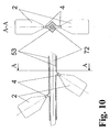
- FIG. 10 shows the same mode of operation for a spherical surface 7, in which case the guide plates 52 must have a concentric curvature in accordance with the surface curvature in order to achieve the same effect of the laminar flow layer.
- FIG. 10 Another special design of beam-shaping device is shown in FIG. 10.
- This example deals with the effective processing of a continuous material flow, in which either an extruded profile 72 or a material flow of identical workpieces are to be processed simultaneously on several surfaces 7 with an active gas jet 6. 10, an extruded profile 72 is guided through a closed processing channel 53, a device according to the invention being attached to at least two opposite sides of this processing channel 53 at an angle to the direction of movement of the extruded profile 72.
- the mass flow of this additive 8 may only make up a fraction of the mass flow of the process gas 1 in the discharge chamber 2.
- the discharge chamber 2 is integrated in a housing 9, since an electrodeless activation of the process gas 1 is to be assumed here.
- the housing 9 symbolizes a waveguide 38 with a connected microwave source 37 according to FIG. 5, but can also accommodate a coil 39 according to FIG. 7 and an associated cooling.
- the activated process gas 1 is guided through a limiting channel 4 with a plurality of parallel individual channels 41, which are arranged in a ring 42.
- the additive 8 is introduced into the center of an active gas jet 6, which approximately represents a gas ring, via this feed channel 82, which is guided from the outside into the center of the ring 42 of the individual channels 41 within the perforated metal plate of the limiting channel 4. Since the active gas jet 6 flows out at a very high speed in the case of the small cross sections of the individual channels 41, the mass flow of the additive 8 can be varied over a wide range via the feed channel 82 and set very precisely. 13 shows the longitudinal and cross-section of the device for generating an electrically neutral active gas jet 6 in a manageable housing 9.
- the device consists of the discharge chamber 2, the delimitation channel 4 and the beam shaping device 5, which as a unitary body 91 in the form of a non-slip handpiece (pen) made of copper or another very good electrical conductor, a rod-shaped central electrode 31, which is arranged by means of an insulating tube 29 made of quartz, coaxial to the wall of the discharge chamber 2, which also represents the hollow electrode 32.
- the insulator tube 29 is sealed in a gas-tight manner with respect to the discharge chamber 21 by an elastic sealing ring 92 in the base body 91.
- the end of the central electrode 31 protrudes from the insulator tube 29 into the discharge chamber 2 by a length of up to twice the diameter of the central electrode 31.
- the insulator tube 29 itself protrudes into the discharge chamber 2 by at least a length the size of its own outside diameter and thus forms part of the discharge chamber 2 in the form of a hollow cylinder outside its outer surface.
- the process gas 1 is introduced symmetrically into the discharge chamber 2 into this hollow cylinder near the rear end wall of the discharge chamber 2.
- the conically tapered end 21 of the discharge chamber 2 merges smoothly into the narrow delimitation channel 4.
- the diameter of the boundary channel 4 is in a ratio of 1: 8 to its length and is only shown in a stylized manner in FIG. 13 (not to scale).
- the beam-shaping device 5 connects to the limiting channel 4.
- the discharge chamber 2, the delimitation channel 4 and the beam-shaping device 5 are made uniformly from copper and have a common grounded contact 93.
- the grounded contact 93 is also connected to the negative pole of the voltage generator 33 (not shown in FIG. 13).
- the positive pole of the voltage generator 33 is connected to the central electrode 31.
- the process gas 1 is initially fed via the gas inlet 24 into a cylindrical distribution chamber 25, from which a spiral gas flow is generated in the hollow-cylindrical part of the discharge chamber 2 by way of uniformly distributed tangential flow channels 26.
- This measure has the effect that the base points of the arc discharge 34 (not shown in FIG. 13) on the central electrode 31 are restricted to its end face and directly adjacent parts of the electrode surface, so that the insulator tube 29 is subjected to less thermal stress and its erosion is reduced.
- an insulating connection body 94 is fastened (eg screwed), which carries the fastening and the connection of the central electrode 31.
- the connection body 94 has an additional gas inlet 27, which is connected to the discharge chamber 2 via a narrow annular chamber 28 along the central electrode 31. Through this narrow annular chamber 28, part of the process gas 1 with the function of electrode cooling and direct feeding into the discharge zone 22 is fed between the central electrode 31 and the insulator tube 29.
- the annular chamber 28 is sealed in the rear in the connecting body 94 by an elastic ring 96 against the central electrode 31, which is guided to the rear to the connecting terminal 95.
- Tangential flow channels 26 can also be provided in the annular chamber 28, as between the distribution chamber 25 and the hollow cylindrical part of the discharge chamber 2, in order to generate a spiral gas circulation.
- 13 now works in the following manner.
- Part of the process gas 1 is supplied through the additional gas inlet 27 and flows through the annular chamber 28 between the central electrode 31 and the insulator tube 29 into the discharge chamber 2.
- the other (larger) part of the process gas 1 through the gas inlet 24 via the distribution chamber 25 , through the tangential openings 26 of the discharge chamber 2 in its hollow cylindrical part, which is formed by the hollow electrode 32 and the protruding insulator tube 29. This creates a spiral eddy flow in the discharge chamber 2.
- the active gas jet 6 is then brought to the width and shape desired for the application (as described, for example, in relation to FIGS. 7 to 9). A chemically very effective and electrically neutral active gas jet 6 is thus available for any application.
Abstract
Description
Ein weiteres gleichartiges Verfahren ist in der DE 195 32 412 A1 beschrieben, bei dem das zu aktivierende Gas in einer Wirbelströmung zuerst in den Bereich einer Entladungszone, die entlang der Achse eines zylindrischen Düsenrohres mit innen isolierter zylindrischer Außenelektrode und koaxialer Zentralelektrode entsteht, eingeleitet sowie aktiviert wird und am Ausgang der Entladungszone, an dem das Düsenrohr in Form einer kreisringförmigen Abschlussfläche der zylindrischen Außenelektrode verengt ist, der Gasstrahl an der Abschlussfläche der Außenelektrode im Wesentlichen entladen wird.
Nachteilig an den vorgenannten Lösungen ist, dass der aus der Düse austretende Gasstrahl ein erhebliches elektrisches Potential besitzt, dessen Wert zwischen dem Potential der geerdeten Ringelektrode und dem der Zentralelektrode liegt. Bei entsprechend großem Gasdurchsatz durch die Austrittsöffnung des Gasstromes wölben sich zusätzlich Entladungsbüschel aus der Düse in Richtung des Aktivgasstrahles aus. Der genannte Nachteil begrenzt die Anwendungsmöglichkeiten der beiden vorgenannten Lösungen a) wegen der Stromschlaggefahr für das Bedienpersonal und b) wegen einer möglichen induzierten Defektbildung durch elektromagnetische Felder bei einer Oberflächenbehandlung von empfindlichen Materialen, wie z.B. Halbleitersubstraten, ggf. auch mit dotierten Schichten oder Strukturen.
Charakteristisch für alle vorgenannten technischen Lösungen ist, dass die Geschwindigkeit, die Temperatur und die Geometrie des Aktivgasstrahls durch die elektrischen, thermischen und gasdynamischen Bedingungen festgelegt werden, die für das Entstehen bzw. Zünden der elektrischen Entladungszone zur Gasaktivierung notwendig sind. Allerdings erweisen sich die genannten Bedingungen zur Gasaktivierung in einer elektrischen Entladungszone nicht immer als optimale Bedingungen für die Oberflächenbehandlung durch den Aktivgasstrahl.
So ist es z.B. sehr problematisch, eine elektrische Entladung bei Atmosphärendruck und den dabei entstehenden Temperaturen von mehr als 5000 K zur Oberflächenbehandlung zu nutzen, da die Mehrzahl der zu bearbeitenden Materialien solchen Temperaturen nicht standhält. Ein weiteres Problem stellen hohe Prozessgasgeschwindigkeiten - z.B. Überschallgeschwindigkeit - für die elektrische Entladungszone dar, da diese unter stark dynamischen Bedingungen nur unter großen Schwierigkeiten aufrechterhalten werden kann. Die erwähnten Anwendungen des Aktivgasstrahles verlangen aber höhere Gasdurchsätze, um die Zeit, innerhalb der der Aktivgasstrahl ausgehend von der Entladungszone die zu bearbeitende Oberfläche erreicht, zu verkürzen, weil damit durch Reduzierung der Rekombinationsvorgänge der Aktivitätsverlust des Gasstrahles wirksam verringert wird.
Die Zentralelektrode ist zweckmäßig stabförmig und im Gaseinlassbereich entlang der Symmetrieachse der Entladungskammer angeordnet.
Die Zentralelektrode kann vorteilhaft, um die Leistung des Aktivgasstrahls durch vergrößerte Elektrodenflächen zu erhöhen, die Form eine Zylinderkappe aufweisen, die eine Zylindermantelfläche geringer Höhe und eine Deckfläche beinhaltet und deren Öffnung koaxial zur Achse der Entladungskammer ausgerichtet und oberhalb des Gaseinlasses der Entladungskammer angeordnet ist.
Das kann zweckmäßig dadurch geschehen, dass die Entladungskammer (1) mit zwei entlang der Wand der Entladungskammer in Strömungsrichtung des Prozessgases angeordneten Elektroden, die mit Radiofrequenz betrieben werden, versehen ist.
Vorteilhaft kann die Hochfrequenzanregung zur Aktivierung des Prozessgases auch durch die Erzeugung eines Induktionsfeldes erreicht werden, indem die Entladungskammer in einer mit Radiofrequenz betriebenen Spule angeordnet ist.
Eine weitere Möglichkeit zur Aktivierung des Prozessgases ohne Kontaminierung des Aktivgases durch Elektrodenmaterial ist dadurch gegeben, dass die Entladungskammer in einem an einer Mikrowellenquelle angeschlossenen Wellenleiter angeordnet ist.
Zur Formung, Wahl der Strömungsart (laminare oder turbulente Strömung) und Einstellung des Aktivgasstrahls mit gewünschten Parametern, insbesondere Geschwindigkeit, Temperatur, geometrische Form und Strömungsart, ist dem Begrenzungskanal zweckmäßig eine strahlformende Einrichtung nachgeordnet.
Dabei kann es von Vorteil sein, dass an den Ausgang des Begrenzungskanals verzweigte Düsen zum Bearbeiten einzelner Teilflächen oder Vertiefungen der zu bearbeitenden Oberfläche angeschlossen sind.
Die strahlformende Einrichtung ist zweckmäßig durch Leitbleche an die Form der zu bearbeitenden Oberfläche angepasst, wobei der Abstand zwischen der Oberfläche und der strahlformenden Einrichtung in einem definiert kleinen Bereich gehalten wird, so dass die effektiv behandelte Oberfläche eine größere Fläche umfasst.
Für spezielle Anwendungen eines Aktivgasstrahles sind strahlformende Einrichtungen vorgesehen, die zwei oder mehrere erfindungsgemäße Vorrichtungen zur Erzeugung des Aktivgasstrahles in einen Bearbeitungskanal einbinden, wobei in dem Bearbeitungskanal bei kontinuierlichem Materialdurchlauf mehrere zu behandelnde Oberflächen eines Werkstücks gleichzeitig oder Oberflächen von Strangprofilen mit beliebigem Querschnitt allseitig bearbeitbar sind.
Es erweist sich zur Erzielung einer definierten Gasströmung als vorteilhaft, wenn der Begrenzungskanal mehrere Einzelkanäle umfasst, um den gasdynamischen Widerstand und die Verweildauer des Aktivgases im Begrenzungskanal zu reduzieren, wobei die Einzelkanäle um einen zentralen Kanal herum gleichmäßig verteilt angeordnet sind. Dabei gestaltet sich die Zufuhr von Zusatzstoffen besonders günstig, wenn der Begrenzungskanal mit mehreren Einzelkanälen einen zentralen Einlasskanal für die Zusatzstoffe aufweist, wobei der Einlasskanal axial im Zentrum eines Ringes von mit Aktivgas durchströmten Einzelkanälen angeordnet ist, da eine vorzeitige Reaktion oder ein Zerfall der Zusatzstoffe sowie eine Kontamination der Entladungskammer durch die Zusatzstoffe vermieden werden kann.
Für alle vorgenannten Zufuhrvarianten sind die Zusatzstoffe im Bereich des Begrenzungskanals vorteilhaft als Gase, Flüssigkeiten in Form von Aerosolen oder Feststoffe in Form feiner Partikel einführbar.
In einer besonders zweckmäßigen Gestaltungsvariante der Erfindung sind die Hohlelektrode, der Begrenzungskanal und die strahlformende Einrichtung als einheitlicher Rotationskörper mit sehr guter elektrischer Leitfähigkeit gefertigt, die Zentralelektrode koaxial von einem Isolatorrohr umgeben in die von der Hohlelektrode gebildete Entladungskammer eingeführt und der Gaseinlass in die Entladungskammer zunächst einer zylindrischen Verteilungskammer zugeführt, wobei für das Prozessgas tangentiale Strömungskanäle von der Verteilungskammer zur Entladungskammer vorgesehen sind, so dass infolge einer resultierenden spiralförmigen Gasströmung aus der Verteilungskammer in die Entladungskammer Bogenentladungen zwischen Zentralelektrode und Hohlelektrode an einem aus dem Isolatorrohr herausragenden Ende der Zentralelektrode fixiert werden. Hierdurch wird eine Erosion des Isolatorrohres weitgehend verhindert. Vorteilhaft können tangentiale Strömungskanäle zusätzlich in eine zylindrische Ringkammer zwischen stabförmiger Zentralelektrode und innerer Oberfläche des Isolatorrohres geführt sein, so dass die Zentralelektrode direkt von einem Anteil des Prozessgases gekühlt wird und Austrittspunkte von Bogenentladungen im Wesentlichen auf nichtzylindrische Flächen der Zentralelektrode beschränkt sind. Dadurch wird das Isolatorrohr noch wirksamer vor der Erosionswirkung des Entladungsbogens geschützt.
Das Isolatorrohr wird zweckmäßig durch die Zentralelektrode um eine Länge von bis zum Zweifachen des Durchmessers der Zentralelektrode überragt. Verwendet man die zusätzlich Prozessgaszufuhr innerhalb des Isolatorrohres, kann das Ende der Zentralelektrode verkürzt werden und schließt im Extremfall mit dem Ende des Isolatorrohrs ab.
Der Begrenzungskanal ist vorzugsweise in Gasströmungsrichtung leicht kegelförmig verengt und weist ein mittleres Verhältnis von Kanaldurchmesser zu Kanallänge von 1:8 auf. Dem Begrenzungskanal schließt sich vorteilhaft eine strahlformende Einrichtung mit glockenförmig verbreitertem Ausgang an, so dass die Arbeitsbreite des Aktivgasstrahles vergrößert wird.
Die Wirksamkeit des Begrenzungskanals hängt dabei wesentlich davon ab, dass er einen kleineren Durchmesser im Verhältnis zur Entladungskammer aufweist. Deshalb ist die Entladungskammer in Strömungsrichtung des Prozessgases konisch verjüngt, so dass bei großem Verhältnis von Querschnitt der Entladungskammer zu Querschnitt des Begrenzungskanals die Geschwindigkeit des Aktivgasstrahls wesentlich ansteigt, wodurch die Zeit, die die chemisch aktiven Teilchen des Aktivgasstrahls benötigen, um die Strecke von der Entladungskammer bis zum Anwendungsort zurückzulegen, stark reduziert wird. Infolge der Zeitverkürzung kommt es zu weniger Rekombinationen aktiver Teilchen (verringerter Aktivitätsverlust des Aktivgasstrahls) und dies führt zu einer Erhöhung der Effektivität des Aktivgasstrahles auf der zu bearbeitenden Oberfläche. Bei sehr hohem Gasdurchsatz durch die Entladungszone wölben sich Entladungsbüschel aus der Entladungszone in den ausströmenden Aktivgasstrahl aus. Die elektrische Leitfähigkeit und der damit verbundene elektrische Widerstand des Plasmabogens bei gleichzeitig hohem Strom führt zu einem erheblichen Potential gegenüber der geerdeten Elektrode auch in naher Distanz des Plasmabogens der geerdeten Elektrode. Um das Austreten der Entladungsbüschel mit gefährlichem elektrischen Potential in den freien Raum zu verhindern, wird der Aktivgasstrahl am Ausgang der Entladungszone durch einen engen geerdeten Kanal geführt. Der Begrenzungskanal ist so dimensioniert, dass ein in ihn eintretender Entladungsbogen ein Potential besitzt, dessen Größe am Eintritt in den Begrenzungskanal für einen Durchbruch zur Kanalwand noch zu gering ist. Mit zunehmender Weglänge im Begrenzungskanal steigt die Spannung im Entladungsbogen so weit an, bis ein Durchbruch zur Kanalwand erfolgt. Damit muss der Begrenzungskanal entsprechend den übrigen Bedingungen der Plasmaerzeugung eine Mindestlänge besitzen, die sicherstellt, dass vorgenannte Auswölbungen der Entladungszone in den freien Raum nicht auftreten können. Das geschieht bei einem Verhältnis des Querschnittes zur Kanallänge von 1:5 bis 1:10.
- Fig. 1:
- eine schematische Darstellung der erfindungsgemäßen Vorrichtung mit elektrischer Entladung, die durch ein beliebiges elektromagnetisches Feld ausgelöst wird;
- Fig. 2:
- eine Ausgestaltung der Erfindung mit elektrischer Bogenentladung zwischen stabförmiger Zentralelektrode und Hohlelektrode an der Wand der Entladungskammer sowie mit einem aus mehreren Einzelkanälen bestehenden Begrenzungskanal;
- Fig. 3:
- eine Gestaltung der Erfindung mit Bogenentladung über eine Zentralelektrode in Form einer Zylinderkappe;
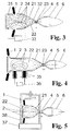
- Fig. 4:
- eine Gestaltungsform mit einem mittels Innenelektroden erzeugten Hochfrequenzfeld;
- Fig. 5:
- eine Ausführungsform mit Erzeugung der Gasentladung durch Mikrowellen;
- Fig. 6:
- eine Gestaltungsform mit einem induktiv erzeugten Hochfrequenzfeld;
- Fig. 7:
- schematische Darstellung der Erfindung zum Aufteilen des Aktivgasstrahls zur gleichzeitigen Bearbeitung einzelner Teilflächen auf Oberflächen mit kompliziertem Relief;
- Fig. 8:
- schematische Darstellung der erfindungsgemäßen Vorrichtung, wobei die strahlformende Einrichtung einer ebenen Oberfläche angepasst ist;
- Fig. 9:
- schematische Darstellung wie in Fig. 8, wobei die strahlformende Einrichtung einer sphärischen Oberfläche angepasst ist;
- Fig. 10:
- eine spezielle Ausgestaltung, bei der mehrere erfindungsgemäße
Vorrichtungen mit deren strahlformenden Einrichtungen in einen
Bearbeitungskanal mit kontinuierlichem Materialfluss eingebunden sind;
eine Gestaltungsform zum Zuführen von Zusatzstoffen in den Aktivgasstrahl vor dem Begrenzungskanal; - Fig. 11:
- eine Gestaltungsform zum Zuführen von Zusatzstoffen vor Beginn des Begrenzungskanals;
- Fig. 12:
- eine Variante zum Zuführen von Zusatzstoffen am Ende des Begrenzungskanals;
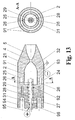
- Fig. 13:
- eine konstruktive Ausführung der Vorrichtung mit spezieller Gestaltung der Strömungskanäle für das zugeführte Prozessgas bei Aktivierung mittels Bogenentladung.
Die Entladungskammer 2 weist in Durchströmungsrichtung des Prozessgases 1 ein konisch verjüngtes Ende 21 (d.h. eine düsenähnlich verengte Form) auf, das der Erhöhung der Strömungsgeschwindigkeit des Prozessgases 1 während seiner Aktivierung in der Entladungskammer 2 dient. Mit dieser Erhöhung der Gasgeschwindigkeit wird die Zeitdauer zum Erreichen einer zu bearbeitenden Oberfläche 7 (nur in Fig. 7 bis 9 dargestellt) verkürzt und damit die Rekombination von aktiven Gasteilchen vor Erreichen des Bearbeitungsortes vermindert. Gleichzeitig mit der Erhöhung der Strömungsgeschwindigkeit erhöht sich jedoch die Gefahr, dass sich eine in der Entladungskammer 2 durch die Wirkung des Feldes 3 ausbildende Entladungszone 22 über das konisch verjüngte Endes 21 der Entladungskammer 2 hinaus nach außerhalb fortsetzt. Um zu verhindern, dass infolge der hohen Gasgeschwindigkeit sogenannte Entladungsbüschel mit gefährlich hohem elektrischen Potential als Auswölbung 24 der Entladungszone 22 aus der Entladungskammer 1 in den freien Raum austreten, wird der durch das verjüngte Ende 21 beschleunigte Aktivgasstrahl 6 am Ausgang der Entladungskammer 1 durch einen engen, geerdeten Begrenzungskanal 4 geführt. Hierdurch wird wirkungsvoll eine Begrenzung der Ausbreitung der Entladungszone 22 in Richtung der freien Austrittsöffnung des Aktivgasstrahls 6 verhindert.
Der Begrenzungskanal 4 ist so dimensioniert, dass der in ihn eintretende Teil der Entladungszone 22 ein solches Potential erreicht, dessen Größe am Eintritt in den Begrenzungskanal 4 für einen Durchbruch zur Kanalwand noch zu gering ist, jedoch mit zunehmender Weglänge im Begrenzungskanal 4 so weit ansteigt, bis ein Durchbruch zur geerdeten Wand des Begrenzungskanals 4 erfolgt.
Des Weiteren muss der Begrenzungskanal 4 entsprechend den übrigen Bedingungen der zur Aktivierung des Prozessgases 1 erforderlichen Plasmaerzeugung eine Mindestlänge besitzen, die sicherstellt, dass vorgenannte Auswölbungen 24 der Entladungszone 22 in den freien Raum nicht geschehen können. Dies wird in der Regel mit einem Verhältnis des Kanalquerschnittes zur Kanallänge von 1:5 bis 1:10 erreicht.
Die Wirksamkeit des Aktivgasstrahles 6 hängt aber auch wesentlich davon ab, dass der Begrenzungskanal 4 einen deutlich kleineren Durchmesser im Verhältnis zum Hauptteil der Entladungskammer 2 (vor deren konisch verjüngtem Ende 21) aufweist, so dass bei großem Verhältnis (1:5 bis 1:8) des Querschnitts der Entladungskammer 2 gegenüber dem Querschnitt des Begrenzungskanals 4 die Geschwindigkeit des Aktivgasstrahls 6 wesentlich ansteigt, wodurch die Zeit, die die chemisch aktiven Teilchen des Aktivgasstrahls 6 benötigen, um die Strecke von der Entladungskammer 2 bis zum Anwendungsort zurückzulegen, stark reduziert wird. Infolge der Zeitverkürzung kommt es zu weniger Rekombinationen aktiver Teilchen (verringerter Aktivitätsverlust des Aktivgasstrahls 6) und dies führt zu einer Erhöhung der Effektivität des Aktivgasstrahles 6 auf der zu bearbeitenden Oberfläche 7 (in Fig. 1 nicht dargestellt). Andererseits wird dadurch jedoch aufgrund des geringen Durchmessers des Begrenzungskanals 4 der aerodynamische Widerstand am verjüngten Ende 21 der Entladungskammer 2 steigen und die Effektivität innerhalb der Entladungszone 22 beeinträchtigen. Dies erklärt sich dadurch, dass die Temperatur des Plasmas mit steigendem Druck zunimmt. Der Begrenzungskanal 4 ist deshalb im Wesentlichen zylinderförmig ausgebildet und weist einen auf den Durchmesser der Entladungskammer 2 angepassten Querschnitt von 1:5 bis 1:8 auf.
Fig. 2 stellt die Erfindung in einer Variante dar, bei der eine Aktivierung des Prozessgases 1 durch eine Bogenentladung 34 zwischen zwei Elektroden in der Entladungskammer 2 erfolgt. Eine der Elektroden ist eine stabförmige Zentralelektrode 31, die andere befindet sich an der Innenwand der Entladungskammer 2 und bildet eine sogenannte Hohlelektrode 32. Die Hohlelektrode 32 ist mindestens an dem konisch verjüngten Ende 21 der Entladungskammer 2 angebracht. Sie kann aber auch selbst die Wand der Entladungskammer 2 bilden (wie z.B. in Fig. 13 dargestellt).
In die Entladungskammer 2, in der zwischen der Zentralelektrode 31 und der Hohlelektrode 32 entlang der inneren Wand der Entladungskammer 2 mittels eines Generators 33 eine elektrische Bogenentladung 34 stattfindet, wird tangential das Prozessgas 1 eingeleitet.
Durch die Wechselwirkung mit der elektrischen Bogenentladung 34 wird das Prozessgas 1 aktiviert, im kegelförmig verjüngten Teil 21 der Entladungskammer 1 beschleunigt und auf dem Weg zum Begrenzungskanal 4 größtenteils entladen. Im nachfolgenden Begrenzungskanal 4, der eine bei großen Gasgeschwindigkeiten mögliche Auswölbung 23 der Entladungszone 22 aufnimmt, wird eine Weiterleitung des elektrischen Potentials der Entladungszone 22 nach außen in den freien Raum der zu bearbeitenden Oberfläche 7 verhindert. Bei sehr hohem Gasdurchsatz durch die Entladungskammer 2 werden Entladungsbüschel in den Aktivgasstrahl des Begrenzungskanals 4 ausgeblasen, d.h. es bildet sich eine Auswölbung 23 der Entladungszone 22. Die elektrische Leitfähigkeit und der damit verbundene elektrische Widerstand des Plasmabogens (elektrischer Entladungsbogen im Prozessgas 1) bei gleichzeitig hohem Strom führt zu einem erheblichen Potential gegenüber der geerdeten Hohlelektrode 32 auch in naher Distanz des Plasmabogens. Es tritt deshalb auch außerhalb der Entladungskammer 2 ein erhebliches elektrisches Potential auf, wenn mit hoher Prozessgasgeschwindigkeit gearbeitet wird. Dieses Potential kann unter Umständen am kreisringförmigen Ende der Hohlelektrode 32 noch einige Hundert Volt betragen. Diese Erscheinung stellt eine Gefährdung für das Bedienpersonal dar, falls an dieser Stelle der Bearbeitungsraum anschließt. Im Fall des Austretens von Entladungsbüscheln könnten außerdem elektrische Defekte an sensiblen Oberflächen zu behandelnder Objekte - z.B. Halbleiter oder Halbleiterstrukturen - hervorgerufen werden. Um das Austreten der Auswölbungen 23 (Entladungsbüschel) mit gefährlichem elektrischen Potential infolge einer hohen Aktivgasstrahlgeschwindigkeit aus der Entladungszone 22 in den freien Raum zu verhindern, wird der Aktivgasstrahl 6 am Ausgang der Entladungskammer 2 durch den engen, geerdeten Begrenzungskanal 4 geleitet, in dem mit einem gewissen aerodynamischen Stau eine weitere Entladung des Aktivgasstrahles 6 erfolgt. Der Begrenzungskanal 4 ist so dimensioniert, dass die in ihn eintretende Auswölbung 23 der Entladungszone 22 ein Potential besitzt, dessen Größe am Eintritt in den Begrenzungskanal 4 für einen Durchbruch zur Kanalwand noch zu gering ist. Mit zunehmender Weglänge im Begrenzungskanal 4 steigt die Spannung im Entladungsbogen so weit an, bis ein Durchbruch zur Kanalwand erfolgt. Somit muss der Begrenzungskanal 4 entsprechend den übrigen Bedingungen der Plasmaerzeugung eine gewisse Mindestlänge besitzen, die sicherstellt, dass vorgenannte Auswölbung 23 der Entladungszone 22 den Begrenzungskanal 4 nicht durchqueren kann und die mit einem Verhältnis zwischen Kanalquerschnitt und Kanallänge von 1/5 bis 1/10 anzugeben ist. Der Aktivgasstrahl 6 weist eine mit der Temperatur am Ausgang der Entladungskammer 2 vergleichbare Temperatur auf, seine gasdynamischen Eigenschaften (Geschwindigkeit und Strömungsverhältnisse) werden jedoch vom Gasdurchsatz und von den Dimensionen und der konstruktiven Gestaltung des Begrenzungskanals 4 wesentlich mitbestimmt.
Nach dem Begrenzungskanal 4 strömt der Aktivgasstrahl 6 durch die strahlformende Einrichtung 5, in der er entsprechend dem Anwendungszweck in bezug auf Geschwindigkeit, Temperatur, geometrische Form und Strömungsart (laminar oder turbulente Strömung) geformt wird. Hierfür können verschiedene Ausführungen von strahlformenden Einrichtungen 5 zur Anwendung gelangen, z.B. Düsen, derartig gestaltet, dass eine adiabatische Expansion des Aktivgaststrahls auftritt, um die Temperatur zu senken, oder abgeflachte strahlformende Einrichtungen 5, wie sie nachfolgend noch näher beschrieben werden, um einen flachen, breiten Aktivgasstrahl 6 zu formen.
Die elektrische Entladungszone 22 kann für die beschriebene Vorrichtung beliebig (je nach Art des verwendeten Spannungsgenerators 33) durch Gleich-, Wechsel- oder Impulsstrom entstehen.
Der in der Entladungskammer 2 erzeugte Aktivgasstrahl 6 verliert beim Durchströmen des Begrenzungskanals 4 leider auch einen Teil seiner Aktivität infolge von Rekombination der aktiven Teilchen und wegen Wechselwirkungen des Aktivgasstrahles 6 mit der Kanalwand. Um die Wirkung vorgenannter Prozesse zu vermindern, ist bei einer Kürzung der Kanallänge eine gleichzeitige Verkleinerung des Querschnitts des Begrenzungskanals 4 erforderlich. Dadurch würde jedoch der aerodynamische Widerstand des Begrenzungskanals 4 steigen und die Effektivität innerhalb der Entladungskammer 2 beeinträchtigt. Dies erklärt sich dadurch, dass die Temperatur des Plasmas mit steigendem Druck zunimmt. Gleichzeitig wird eine stärkere thermische Belastung der Zentralelektrode 31 und Hohlelektrode 32 verursacht, die zu höherem Elektrodenverschleiß führt. Dies kann dadurch vermindert werden, dass der Begrenzungskanal 4 aus zwei oder mehreren geerdeten Einzelkanälen 41 besteht, die in elektrisch leitendem Material parallel zueinander angeordnet sind und einen größeren effektiven Strömungsquerschnitt ergeben. Fig. 2 zeigt dazu eine Ausführung, bei der um einen zentralen Einzelkanal 41 herum weitere Einzelkanäle 41 gleichmäßig verteilt angeordnet sind.
Fig. 3 stellt eine Erzeugung eines Aktivgasstrahles 6 dar, bei der - im Unterschied zum oben beschriebenen Beispiel - die Zentralelektrode 31 anstatt der Stabform die Form einer elektrisch leitenden Zylinderkappe aufweist. Diese Zentralelektrode 31 ist mit ihrer Öffnung in Richtung der Entladungskammer 2 koaxial angeordnet. Das Prozessgas 1 wird tangential in einen Spalt zwischen der zylindrischen Zentralelektrode 31 und der Entladungskammer 2 eingeleitet. Beim Einsatz einer solchen Form der Zentralelektrode 31 vergrößert sich die Stützfläche der Bogenentladung 34 auf der Zentralelektrode 31, d.h. die Fußpunkte der Bogenentladungen 34 bewegen sich bei intensiv verwirbelter Strömung des Prozessgases 1 auf einer größeren Oberfläche. Dadurch wird bei der Zentralelektrode 31 eine Überhitzung verhindert und die Lebensdauer sowie der maximale Entladungsstrom erhöht.
In Fig. 4 ist eine Variante dargestellt, bei der das Prozessgas 1 zwischen zwei in der Entladungskammer 2 in Strömungsrichtung nacheinander angeordneten Elektroden 35 aktiviert wird. Mittels eines Hochfrequenzgenerators 36 wird die Entladungszone 22 durch eine Hochfrequenzentladung in einem Wechselfeld 3 erzeugt, wobei die Entladungskammer 2 aus elektrisch isolierendem Material (z.B. Quarz) besteht.
Da hinlänglich bekannt ist, dass die bei Verwendung von kalten Elektroden 35 entstehende elektrische Entladung unter bestimmten Drücken, z.B. bei Atmosphärendruck, ohne zusätzliche Maßnahmen instabil ist, weil hohe Elektronendichten und Energiegradienten vor den Elektroden 35 eine Raumladungsschicht erzeugen und die Entladung destabilisieren. In Hochfrequenzentladungen wird diese Stabilisierung durch einfache Maßnahmen (wie sie beispielsweise von J. Reece Roth in: Industrial Plasma Engineering, Vol. 1: Principles, Inst. of Physics Publishing, Bristol and Philadelphia, 1995, S. 382-385, 404-407, 464f. beschrieben sind) erzielt. Aus diesem Grund der einfachen Erhaltung einer stabilen Entladung ist eine HF-Entladung zur Aktivierung des Prozessgases 1 besonders vorteilhaft.
Sämtliche Elektroden, wie sie in den vorhergehenden Gestaltungsvarianten zur Erzeugung der elektrischen Entladungszone 22 beschrieben wurden, sind jedoch mehr oder weniger einem Erosionsprozess ausgesetzt, d.h. sie verschleißen. Das führt zu einer Kontamination der Entladungskammer 2 und des Prozessgases 1 durch Elektrodenmaterial. Um einen von Kontaminierung durch Elektrodenmaterial freien Aktivgasstrahl 6 zu erzeugen, wird gemäß Fig. 5 die Entladungszone 22 ohne Elektroden erzeugt. Dazu wird die in diesem Beispiel aus elektrisch isolierendem, aber mikrowellentransparentem Material bestehende Entladungskammer 2 in das Feld 3 eines Mikrowellengenerators 37 eingebracht, wobei in einem typischen Mikrowellenleiter 38, der an den Mikrowellengenerator 37 angeschlossen ist, ein Ort relativ gleichmäßiger und hoher Feldstärke genutzt wird. Alle übrigen Abläufe, die aus der Entladungszone 22 den Aktivgasstrahl 6 hervorbringen, laufen entsprechend den vorhergehenden Beispielen ab.
Eine ebenfalls elektrodenlose Aktivierung des Prozessgases 1 ist in Fig. 6 dargestellt. Hier wird ein Hochfrequenzgenerator 36 dazu benutzt, mit einer Spule 39 ein hochfrequent wechselndes Feld 3 in der Entladungskammer 2 zu induzieren. Dabei ist die Entladungskammer 2 innerhalb der Windungen der Spule 39 angeordnet und bildet innen die gewünschte Entladungszone 22 aus. Das Material der Entladungskammer 2 ist relativ frei wählbar, jedoch notwendig nicht ferromagnetisch. Wie bereits in den vorherigen Beispielen beschrieben, wird das Prozessgas 1 im konisch verjüngten Ende 21 der Entladungskammer 2 beschleunigt und im geerdeten Begrenzungskanal 4 von seinem gefährlichen Potential befreit, so dass am Ausgang der strahlformenden Einrichtung 5 ein elektrisch neutraler Aktivgasstrahl 6 zur Verfügung steht.
Eine weitere spezielle Gestaltung von strahlformender Einrichtung ist in Fig. 10 gezeigt. Dieses Beispiel beschäftigt sich mit der effektiven Bearbeitung eines kontinuierlichen Materialflusses, bei dem entweder ein Strangprofil 72 oder ein Materialfluss identischer Werkstücke gleichzeitig an mehreren Oberflächen 7 mit einem Aktivgasstrahl 6 bearbeitet werden sollen. In Fig. 10 wird ein Strangprofil 72 durch einen geschlossenen Bearbeitungskanal 53 geführt, wobei an wenigstens zwei gegenüberliegenden Seiten dieses Bearbeitungskanals 53 schräg zur Bewegungsrichtung des Strangprofils 72 jeweils eine erfindungsgemäße Vorrichtung angebracht ist.
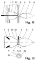
Alle bisher beschriebenen Anordnungen beinhalten nur den Einsatz eines Prozessgases oder Prozessgasgemisches, das direkt in die Entladungskammer 1 in entsprechender Anordnung eingeleitet wird. Soll ein zusätzlicher Stoff zugesetzt werden, der nicht in der Entladungszone 22 aktiviert werden soll, so kommen zwei mögliche Anordnungen in Frage, die entweder gemäß Fig. 11 durch Zugabe unmittelbar vor dem Begrenzungskanal 4 oder gemäß Fig. 12 durch Einleitung direkt in den neutralen Aktivgasstrahl 6 nach dem Begrenzungskanal 4 in der Strahlformungseinrichtung 5 realisiert werden können.
Im ersten Fall (Fig. 11) wird hierzu der Zusatzstoff 8 über ein hochtemperaturfestes Zufuhrrohr 81 zugeführt, das wenige Millimeter vor dem der Entladungszone 22 zugewandten Ende des Begrenzungskanals 4 endet und aus Keramik, Quarz oder einem vergleichbar temperaturbeständigen Material besteht. Um möglichst keine Störung durch diesen Zusatzstoff 8 in der Entladungszone 22 zu erhalten, darf der Massenstrom dieses Zusatzstoffes 8 nur einen Bruchteil des Massenstroms des Prozessgases 1 in der Entladungskammer 2 ausmachen. Die Entladungskammer 2 ist in dieser Ausführungsform in ein Gehäuse 9 eingebunden, da hier eine elektrodenlose Aktivierung des Prozessgases 1 angenommen werden soll. Das Gehäuse 9 symbolisiert im einfachsten Fall einen Wellenleiter 38 mit angeschlossener Mikrowellenquelle 37 gemäß Fig. 5, kann aber auch eine Spule 39 gemäß Fig. 7 sowie eine zugehörige Kühlung aufnehmen.
Im zweiten Fall (Fig. 12) wird das aktivierte Prozessgas 1 durch einen Begrenzungskanal 4 mit mehreren parallelen Einzelkanälen 41, die in einem Ring 42 angeordnet sind, geführt. Im Zentrum des als dicke Lochplatte ausgebildeten Begrenzungskanals 4 befindet sich anstelle eines zentralen Einzelkanals 41 ein Zufuhrkanal 82, der von außen zugeleitet wird. Über diesen Zufuhrkanal 82, der innerhalb der metallischen Lochplatte des Begrenzungskanals 4 von außen in die Mitte des Ringes 42 der Einzelkanäle 41 geführt ist, wird der Zusatzstoff 8 in das Zentrum eines Aktivgasstrahls 6, der näherungsweise einen Gasring darstellt, eingebracht. Da der Aktivgasstrahl 6 bei den geringen Querschnitten der Einzelkanäle 41 mit sehr hoher Geschwindigkeit ausströmt, kann der Massenstrom des Zusatzstoffes 8 über den Zufuhrkanal 82 über einen großen Bereich variiert und sehr genau eingestellt werden.
Die Fig. 13 stellt den Längs- und Querschnitt der Vorrichtung für die Erzeugung eines elektrisch neutralen Aktivgasstrahls 6 in einem handhabbaren Gehäuse 9 dar. Die Vorrichtung besteht aus Entladungskammer 2, Begrenzungskanal 4 und Strahlformungseinrichtung 5, die als ein einheitlicher Grundkörper 91 in der Form eines griffigen Handstückes (Pen) aus Kupfer oder einem anderen sehr guten elektrischen Leiter gebildet sind, einer stabförmigen Zentralelektrode 31, die mittels eines aus Quarz bestehenden Isolatorrohres 29, koaxial zu der Wand der Entladungskammer 2, die zugleich die Hohlelektrode 32 darstellt, angeordnet ist. Das Isolatorrohr 29 wird durch einen elastischen Dichtungsring 92 im Grundkörper 91 gasdicht bezüglich der Entladungskammer 21 abgedichtet. Das Ende der Zentralelektrode 31 steht aus dem Isolatorrohr 29 um eine Länge von bis zum zweifachen Durchmesser der Zentralelektrode 31 in die Entladungskammer 2 vor. Das Isolatorrohr 29 selbst ragt mindestens um eine Länge von der Größe des eigenen Außendurchmessers in die Entladungskammer 2 hinein und bildet somit außerhalb seiner Mantelfläche einen Teil der Entladungskammer 2 in Form eines Hohlzylinders. In diesen Hohlzylinder nahe der hinteren Stirnwand der Entladungskammer 2 wird das Prozessgas 1 symmetrisch in die Entladungskammer 2 eingeleitet.
Das konisch verjüngte Ende 21 der Entladungskammer 2 geht fließend in den engen Begrenzungskanal 4 über. Der Durchmesser des Begrenzungskanals 4 steht im Verhältnis 1:8 zu dessen Länge und ist in Fig. 13 nur stilisiert (nicht maßstabsgerecht) gezeichnet. An den Begrenzungskanal 4 schließt sich die strahlformende Einrichtung 5 an. Die Entladungskammer 2, der Begrenzungskanal 4 und die strahlformende Einrichtung 5 sind einheitlich aus Kupfer gefertigt und weisen einen gemeinsamen geerdeten Kontakt 93 auf. Der geerdete Kontakt 93 ist zugleich mit dem negativen Pol des Spannungsgenerators 33 (in Fig. 13 nicht dargestellt) verbunden. Der positive Pol des Spannungsgenerators 33 ist an die Zentralelektrode 31 angeschlossen.
Die Zufuhr des Prozessgases 1 erfolgt über den Gaseinlass 24 zunächst in eine zylindrische Verteilungskammer 25, von der aus über gleichmäßig verteilte tangentiale Strömungskanäle 26 eine spiralförmige Gasströmung im hohlzylinderförmigen Teil der Entladungskammer 2 generiert wird. Diese Maßnahme bewirkt, dass die Fußpunkte der Bogenentladung 34 (in Fig. 13 nicht darstellt) an der Zentralelektrode 31 auf deren Stirnfläche und unmittelbar angrenzende Teile der Elektrodenoberfläche einschränkt werden, so dass das Isolatorrohr 29 thermisch weniger belastet und dessen Erosion verringert wird.
Am rückwärtigen Ende des Grundkörpers 91 - genauer gesagt an der hinteren Stirnwand der Entladungskammer 2 ist ein isolierender Anschlusskörper 94 befestigt (z.B. geschraubt), der die Befestigung und den Anschluss der Zentralelektrode 31 trägt. Der Anschlusskörper 94 weist einen zusätzlichen Gaseinlass 27 auf, der über eine schmale Ringkammer 28 entlang der Zentralelektrode 31 mit der Entladungskammer 2 verbunden ist. Durch diese schmale Ringkammer 28 wird zwischen Zentralelektrode 31 und Isolatorrohr 29 ein Teil des Prozessgases 1 mit der Funktion einer Elektrodenkühlung und direkter Einspeisung in die Entladungszone 22 zugeführt. Die Ringkammer 28 wird rückwärtig im Anschlusskörper 94 durch einen elastischen Ring 96 gegen die Zentralelektrode 31, die nach hinten zur Anschlussklemme 95 hindurch geführt ist, abgedichtet. Auch in die Ringkammer 28 können - wie zwischen der Verteilungskammer 25 und dem hohlzylindrischen Teil der Entladungskammer 2 - tangentiale Strömungskanäle 26 (für Ringkammer 28 nicht dargestellt) zur Erzeugung einer spiralförmigen Gaszirkulation vorgesehen sein.
Die Vorrichtung nach Fig. 13 funktioniert nun in folgender Art und Weise. Ein Teil des Prozessgases 1 wird durch den zusätzlichen Gaseinlass 27 zugeführt und strömt durch die Ringkammer 28 zwischen der Zentralelektrode 31 und dem Isolatorrohr 29 in die Entladungskammer 2. Gleichzeitig wird der andere (größere) Teil des Prozessgases 1 durch den Gaseinlass 24 über die Verteilungskammer 25, durch die tangentialen Öffnungen 26 der Entladungskammer 2 in deren hohlzylinderförmigen Teil, der durch die Hohlelektrode 32 und das hereinragende Isolatorrohr 29 gebildet wird, zugeführt. Dadurch wird eine spiralförmige Wirbelströmung in der Entladungskammer 2 erzeugt. Bei der Zufuhr des Prozessgases 1 durch die Gaseinlässe 24 und 27 und gleichzeitigem Anliegen einer Gleichspannung zwischen geerdetem Kontakt 93 und Anschlussklemme 95 entsteht eine elektrische Entladung in der Entladungskammer 2. Das Prozessgas 1 wird aufgrund der Wechselwirkungen in der Entladungszone 22 (analog zu Fig. 2, jedoch in Fig. 13 nicht dargestellt) aktiviert, verlässt die Entladungskammer 2 - durch deren konisch verjüngtes Ende 21 beschleunigt - mit hoher Geschwindigkeit und strömt durch den anschließenden Begrenzungskanal 4 sowie die strahlformende Einrichtung 5 in den (freien) Bearbeitungsraum. Der Aktivgasstrahl 6 verliert im Wesentlichen im Begrenzungskanal 4 sein Potential, dessen Größe am Ende des Begrenzungskanals 4 gegenüber Masse (geerdet) nahezu Null ist. In der nachfolgenden strahlformenden Einrichtung 5 wird der Aktivgasstrahl 6 dann auf die für die Anwendung gewünschte Breite und Form (wie beispielhaft zu den Figuren 7 bis 9 beschrieben) gebracht. Damit steht ein chemisch sehr wirkungsvoller und elektrisch neutraler Aktivgasstrahl 6 für beliebige Anwendungsfälle zur Verfügung.
- 1
- Prozessgas
- 2
- Entladungskammer
- 21
- konisch verjüngtes Ende
- 22
- Entladungszone
- 23
- Auswölbung der Entladungszone
- 24
- tangentiale Strömungskanäle
- 25
- Verteilungskammer
- 26, 27
- Gaseinlass
- 28
- Ringkammer
- 29
- Isoiatorrohr
- 3
- Feld
- 31
- Zentralelektrode
- 32
- Hohlelektrode
- 33
- Spannungsgenerator
- 34
- Bogenentladung
- 35
- HF-Elektrode
- 36
- HF-Quelle
- 37
- Mikrowellenquelle
- 38
- Mikrowellenleiter
- 39
- Spule
- 4
- Begrenzungskanal
- 41
- Einzelkanäle
- 42
- Ring (von Einzelkanälen)
- 5
- strahlformende Einrichtung
- 51
- verzweigte Düsen
- 52
- Leitbleche
- 53
- Bearbeitungskanal
- 6
- Aktivgasstrahl
- 61
- Teilstrahlen
- 7
- Oberfläche
- 71
- Teilflächen
- 72
- Strangprofil
- 8
- Zusatzstoffe
- 81
- Zufuhrrohr
- 82
- Zufuhrkanal
- 9
- Gehäuse
- 91
- Grundkörper
- 92
- elastischer Dichtungsring
- 93
- Erdungsklemme
- 94
- isolierender Anschlusskörper
- 95
- Anschlussklemme (der Zentralelektrode)
- 96
- elastischer Ring
Claims (24)
- Vorrichtung zum Erzeugen eines chemisch aktiven Strahls (Aktivgasstrahls) mittels eines durch elektrische Entladung generierten Plasmas in einem verwendeten Prozessgas mit einer im Wesentlichen zylindrischen Entladungskammer, die von einem Prozessgas durchströmt wird und in der zur Aktivierung des Prozessgases eine Plasmaerzeugung infolge einer elektrischen Gasentladung vorgesehen ist, einem Gaseinlass zum kontinuierlichen Zuführen des Prozessgases in die Entladungskammer sowie einer Austrittsöffnung zum Ausrichten des Aktivgasstrahles auf eine zu bearbeitende Oberfläche, dadurch gekennzeichnet, dassdie Entladungskammer (2) ein konisch verjüngtes Ende (21) zur Erhöhung der Geschwindigkeit des Aktivgasstrahls (6) aufweist unddem verjüngten Ende (21) der Entladungskammer (2) ein Begrenzungskanal (4) zur Verhinderung der Ausbreitung der Entladungszone (22) in den freien Raum für die zu bearbeitende Oberfläche (7) nachgeordnet ist, wobei der Begrenzungskanal (4) im Wesentlichen zylinderförmig ausgebildet und geerdet ist und dessen Länge um den Faktor 5 bis 10 größer als sein Querschnitt ist.
- Vorrichtung nach Anspruch 1, dadurch gekennzeichnet, dass
zur Aktivierung des Prozessgases (1) eine Bogenentladung (34) vorgesehen ist, wobei die Entladungskammer (2) eine Zentralelektrode (31) und eine Hohlelektrode (32), die die Innenwand der Entladungskammer (2) mindestens im Bereich des konisch verjüngten Endes (21) flächig und symmetrisch bedeckt, aufweist. - Vorrichtung nach Anspruch 2, dadurch gekennzeichnet, dass
der Begrenzungskanal (4) direkt an die Hohlelektrode (32) angefügt ist. - Vorrichtung nach Anspruch 2, dadurch gekennzeichnet, dass
die Zentralelektrode (31) stabförmig ausgebildet und entlang der Symmetrieachse der Entladungskammer (2) angeordnet ist. - Vorrichtung nach Anspruch 2, dadurch gekennzeichnet, dass
die Zentralelektrode (31) die Form einer Zylinderkappe aufweist, die eine Zylindermantelfläche geringer Höhe sowie eine Deckfläche beinhaltet und deren Öffnung koaxial zur Symmetrieachse der Entladungskammer (2) ausgerichtet und oberhalb des Gaseinlasses (26) der Entladungskammer (2) angeordnet ist. - Vorrichtung nach Anspruch 1, dadurch gekennzeichnet, dass
zur Aktivierung des Prozessgases (1) die Entladungskammer (2) in einem mit Hochfrequenz (Radiofrequenz) erzeugten Induktionsfeld angebracht ist. - Vorrichtung nach Anspruch 6, dadurch gekennzeichnet, dass
zur Aktivierung des Prozessgases (1) die Entladungskammer (2) mit zwei entlang der Wand der Entladungskammer (2) in Strömungsrichtung des Prozessgases (1) angeordneten HF-Elektroden (35), die mit Radiofrequenz betrieben werden, versehen ist. - Vorrichtung nach Anspruch 6, dadurch gekennzeichnet, dass
zur Aktivierung des Prozessgases (1) die Entladungskammer (2) in einer mit Hochfrequenz betriebenen Spule (39) angeordnet ist. - Vorrichtung nach Anspruch 1, dadurch gekennzeichnet, dass
zur Aktivierung des Prozessgases (1) die Entladungskammer (2) in einem an einer Mikrowellenquelle (37) angeschlossenen Wellenleiter (38) angeordnet ist. - Vorrichtung nach Anspruch 1, dadurch gekennzeichnet, dass
dem Begrenzungskanal (4) eine strahlformende Einrichtung (5) zur Einstellung des Aktivgasstrahls (6) mit gewünschten Parametern, insbesondere Geschwindigkeit, Temperatur, geometrische Form und Strömungsart, nachgeordnet ist. - Vorrichtung nach Anspruch 10, dadurch gekennzeichnet, dass
an den Ausgang des Begrenzungskanals (4) verzweigte Düsen (51) zum Bearbeiten einzelner Teilflächen (71) oder Vertiefungen der zu bearbeitenden Oberfläche (7) angeschlossen sind. - Vorrichtung nach Anspruch 10, dadurch gekennzeichnet, dass
die strahlformende Einrichtung (5) durch Leitbleche (52) an die Form der zu bearbeitenden Oberfläche (7) angepasst ist, wobei der Abstand zwischen der Oberfläche (7) und den Leitblechen (52) in einem definiert kleinen Bereich gehalten wird, so dass die effektiv behandelte Oberfläche (7) eine größere Fläche umfasst. - Vorrichtung nach Anspruch 10, dadurch gekennzeichnet, dass
strahlformende Einrichtungen (5) vorgesehen sind, die zwei oder mehrere erfindungsgemäße Vorrichtungen zur Erzeugung des Aktivgasstrahles (6) in einen Bearbeitungskanal (53) einbinden, wobei in dem Bearbeitungskanal (53) bei kontinuierlichem Materialdurchlauf mehrere zu behandelnde Oberflächen (7) eines Werkstücks gleichzeitig oder Oberflächen (7) von Strangprofilen (72) mit beliebigem Querschnitt allseitig bearbeitbar sind. - Vorrichtung nach Anspruch 1, dadurch gekennzeichnet, dass
ein in der Entladungskammer (2) axial angeordnetes Zufuhrrohr (81), das kurz vor dem Ausgang der Entladungskammer (2) endet, zur Einbringung von Zusatzstoffen (8) in den Aktivgasstrahl (6) vorgesehen ist, wobei ein Einfluss der Zusatzstoffe (8) auf die Entladungscharakteristik und eine Kontaminierung der Entladungskammer (2) durch die Zusatzstoffe (8) oder deren Reaktionsprodukte vermieden wird. - Vorrichtung nach Anspruch 1, dadurch gekennzeichnet, dass
der Begrenzungskanal (4) mehrere Einzelkanäle (41) umfasst, um den gasdynamischen Widerstand und die Verweildauer des Aktivgases (6) im Begrenzungskanal (4) zu reduzieren, wobei die Einzelkanäle (41) um einen zentralen Kanal herum gleichmäßig in einem Ring (42) verteilt angeordnet sind. - Vorrichtung nach Anspruch 15, dadurch gekennzeichnet, dass
der Begrenzungskanal (4) mit mehreren Einzelkanälen (41) einen zentralen Zufuhrkanal (82) für Zusatzstoffe (8) aufweist, wobei der Zufuhrkanal (82) axial im Zentrum des Ringes (42) von mit aktiviertem Prozessgas (6) durchströmten Einzelkanälen (41) angeordnet ist. - Vorrichtung nach Anspruch 14 oder 16, dadurch gekennzeichnet dass
die Zusatzstoffe (8) im Bereich des Begrenzungskanals (4) als Gase, Flüssigkeiten in Form von Aerosolen oder Feststoffe in Form feiner Partikel einführbar sind. - Vorrichtung nach Anspruch 4, dadurch gekennzeichnet, dass
die Hohlelektrode (32), der Begrenzungskanal (4) und die strahlformende Einrichtung (5) als einheitlicher Rotationskörper mit sehr guter elektrischer Leitfähigkeit gefertigt sind, die Zentralelektrode (31) als koaxial von einem Isolatorrohr (29) umgebene stabförmige Zentralelektrode (31) in die Entladungskammer (2), die von der Hohlelektrode (32) gebildet wird, eingeführt ist, und die Gaszufuhr für das Prozessgas (1) tangentiale Strömungskanäle (24) in einer die Zentralelektrode (31) konzentrisch umgebenden zylindrischen Verteilungskammer (15; 16) aufweist, wobei infolge einer resultierenden spiralförmigen Gasströmung aus der Verteilungskammer (15; 16) in die Entladungskammer (2) Bogenentladungen (34) zwischen Zentralelektrode (31) und Hohlelektrode (32) einen auf das Ende der Zentralelektrode (31) konzentrierten Austrittsbereich aufweisen. - Vorrichtung nach Anspruch 18, dadurch gekennzeichnet, dass
tangentiale Strömungskanäle (24) in einen zylindrischen ringförmigen Teil der Entladungskammer (2) zwischen innerer Oberfläche der Hohlelektrode (32) und äußerer Oberfläche des Isolatorrohres (29) geführt sind, so dass das Prozessgas (1) das Isolatorrohr (29) von.außen spiralförmig umströmt. - Vorrichtung nach den Anspruch 18, dadurch gekennzeichnet, dass
tangentiale Strömungskanäle (24) zusätzlich in eine zylindrische Ringkammer (28) zwischen stabförmiger Zentralelektrode (31) und innerer Oberfläche des Isolatorrohres (29) geführt sind, so dass die Zentralelektrode (31) direkt von einem Anteil des Prozessgases (1) gekühlt wird und Austrittspunkte von Bogenentladungen (34) im Wesentlichen auf nichtzylindrische Flächen der Zentralelektrode (31) beschränkt sind. - Vorrichtung nach Anspruch 19, dadurch gekennzeichnet, dass
das Ende der stabförmigen Zentralelektrode (31) das Isolatorrohr (29) um eine Länge von bis zum zweifachen Durchmesser der Zentralelektrode (31) überragt. - Vorrichtung nach Anspruch 19 oder 20, dadurch gekennzeichnet, dass
das Ende der Zentralelektrode (31) mit dem Ende des Isolatorrohrs (29) abschließt. - Vorrichtung nach Anspruch 18, dadurch gekennzeichnet, dass
der Begrenzungskanal (4) in Gasströmungsrichtung leicht kegelförmig verengt ist und ein mittleres Verhältnis von Kanaldurchmesser zu Kanallänge von 1:8 aufweist. - Vorrichtung nach Anspruch 18, dadurch gekennzeichnet, dass
dem Begrenzungskanal (4) eine strahlformende Einrichtung (5) mit glockenförmig erweitertem Ausgang nachgeordnet ist, so dass die Arbeitsbreite des Aktivgasstrahles (6) vergrößert ist.
Applications Claiming Priority (2)
| Application Number | Priority Date | Filing Date | Title |
|---|---|---|---|
| DE10145131A DE10145131B4 (de) | 2001-09-07 | 2001-09-07 | Vorrichtung zum Erzeugen eines Aktivgasstrahls |
| DE10145131 | 2001-09-07 |
Publications (4)
| Publication Number | Publication Date |
|---|---|
| EP1292176A2 true EP1292176A2 (de) | 2003-03-12 |
| EP1292176A3 EP1292176A3 (de) | 2008-07-02 |
| EP1292176B1 EP1292176B1 (de) | 2009-12-09 |
| EP1292176B8 EP1292176B8 (de) | 2010-05-19 |
Family
ID=7698901
Family Applications (1)
| Application Number | Title | Priority Date | Filing Date |
|---|---|---|---|
| EP02019754A Expired - Lifetime EP1292176B8 (de) | 2001-09-07 | 2002-09-04 | Vorrichtung zum Erzeugen eines Aktivgasstrahls |
Country Status (6)
| Country | Link |
|---|---|
| US (1) | US6943316B2 (de) |
| EP (1) | EP1292176B8 (de) |
| AT (1) | ATE451824T1 (de) |
| CA (1) | CA2399493C (de) |
| DE (2) | DE10145131B4 (de) |
| ES (1) | ES2337657T3 (de) |
Cited By (1)
| Publication number | Priority date | Publication date | Assignee | Title |
|---|---|---|---|---|
| EP1604773A1 (de) * | 2004-06-09 | 2005-12-14 | Jenoptik Automatisierungstechnik GmbH | Verfahren zur Vorbehandlung verzinkter Stahlbleche oder Aluminiumbleche zum Schweissen |
Families Citing this family (20)
| Publication number | Priority date | Publication date | Assignee | Title |
|---|---|---|---|---|
| DE10358329B4 (de) | 2003-12-12 | 2007-08-02 | R3T Gmbh Rapid Reactive Radicals Technology | Vorrichtung zur Erzeugung angeregter und/oder ionisierter Teilchen in einem Plasma und Verfahren zur Erzeugung ionisierter Teilchen |
| US7148456B2 (en) * | 2004-09-15 | 2006-12-12 | The Penn State Research Foundation | Method and apparatus for microwave phosphor synthesis |
| US7079962B2 (en) * | 2004-10-20 | 2006-07-18 | Itron, Inc. | Automated utility meter reading system with variable bandwidth receiver |
| WO2006048649A1 (en) * | 2004-11-05 | 2006-05-11 | Dow Corning Ireland Limited | Plasma system |
| SK51082006A3 (sk) * | 2006-12-05 | 2008-07-07 | Fakulta Matematiky, Fyziky A Informatiky Univerzitfakulta Matematiky, Fyziky A Informatiky Univerzity Komensk�Hoy Komensk�Ho | Zariadenie a spôsob úpravy povrchov kovov a metaloZariadenie a spôsob úpravy povrchov kovov a metaloidov, oxidov kovov a oxidov metaloidov a nitridovidov, oxidov kovov a oxidov metaloidov a nitridovkovov a nitridov metaloidovkovov a nitridov metaloidov |
| DE102006060942A1 (de) * | 2006-12-20 | 2008-06-26 | Plasma Treat Gmbh | Vorrichtung und Verfahren zur Erzeugung eines Plasmastrahls |
| DE102007002161B4 (de) * | 2007-01-15 | 2011-11-10 | Sergei Afanassev | Elektrischer Raketenmotor mit pulverförmigem Betriebsstoff |
| DE202007019099U1 (de) * | 2007-03-17 | 2010-08-05 | Je Plasmaconsult Gmbh | Vorrichtung zur Plasmabehandlung |
| DE102007024090A1 (de) | 2007-05-22 | 2008-11-27 | Diener, Christof, Dipl.-Ing. | Plasmabehandlungsvorrichtung |
| EP2297377B1 (de) * | 2008-05-30 | 2017-12-27 | Colorado State University Research Foundation | Auf plasma basierende chemikalienquellenvorrichtung und verfahren zu ihrer verwendung |
| CH700049A2 (fr) * | 2008-12-09 | 2010-06-15 | Advanced Machines Sarl | Procédé et dispositif de génération d'un flux de plasma. |
| KR101001477B1 (ko) | 2009-02-27 | 2010-12-14 | 아주대학교산학협력단 | 바이오-메디컬 응용을 위한 상압 저온 마이크로 플라즈마 분사 장치 |
| FR2955628B1 (fr) * | 2010-01-27 | 2013-10-04 | Centre Nat Rech Scient | Procede et dispositif de modulation du debit massique d'un ecoulement de gaz |
| TWI432228B (zh) * | 2010-09-07 | 2014-04-01 | Univ Nat Cheng Kung | 微電漿產生裝置及其滅菌系統 |
| KR101730094B1 (ko) * | 2013-08-30 | 2017-04-25 | 내셔날 인스티튜트 오브 어드밴스드 인더스트리얼 사이언스 앤드 테크놀로지 | 마이크로파 플라스마 처리 장치 |
| ITPD20130310A1 (it) | 2013-11-14 | 2015-05-15 | Nadir S R L | Metodo per la generazione di un getto o jet di plasma atmosferico e dispositivo minitorcia al plasma atmosferico |
| DE102014118909B4 (de) | 2014-02-05 | 2016-12-29 | Wilhelm Niemann GmbH & Co. KG Maschinenfabrik | Tauchmühle mit Mahlraumabdichtung |
| CN108714735A (zh) * | 2018-08-11 | 2018-10-30 | 刘冠诚 | 一种等离子焰扩散咀 |
| DE102018221191A1 (de) | 2018-12-07 | 2020-06-10 | Carl Zeiss Smt Gmbh | Optisches Element zur Reflexion von VUV-Strahlung und optische Anordnung |
| CN111465160A (zh) * | 2020-05-14 | 2020-07-28 | 国网重庆市电力公司电力科学研究院 | 一种等离子体射流发生装置及系统 |
Citations (9)
| Publication number | Priority date | Publication date | Assignee | Title |
|---|---|---|---|---|
| US3042830A (en) * | 1960-04-04 | 1962-07-03 | Mhd Res Inc | Method and apparatus for effecting gas-stabilized electric arc reactions |
| US3239130A (en) * | 1963-07-10 | 1966-03-08 | Cons Vacuum Corp | Gas pumping methods and apparatus |
| US3264508A (en) * | 1962-06-27 | 1966-08-02 | Lai William | Plasma torch |
| US4140892A (en) * | 1976-02-16 | 1979-02-20 | Niklaus Muller | Plasma-arc spraying torch |
| US4916273A (en) * | 1987-03-11 | 1990-04-10 | Browning James A | High-velocity controlled-temperature plasma spray method |
| EP0851040A1 (de) * | 1995-08-29 | 1998-07-01 | Komatsu Ltd. | Oberflächenbehandlungsvorrichtung mit gasjet |
| DE29919142U1 (de) * | 1999-10-30 | 2001-03-08 | Agrodyn Hochspannungstechnik G | Plasmadüse |
| DE10115241A1 (de) * | 2001-03-28 | 2002-10-24 | Aurion Anlagentechnik Gmbh | Vorrichtung und Verfahren zur atmosphärischen Plasmabehandlung |
| DE10303402A1 (de) * | 2003-01-24 | 2004-08-12 | Pva Tepla Ag | Vorrichtung zum Erzeugen eines breiten Aktivgasstrahls auf Basis eines Gasentladungsplasmas |
Family Cites Families (11)
| Publication number | Priority date | Publication date | Assignee | Title |
|---|---|---|---|---|
| US4800716A (en) * | 1986-07-23 | 1989-01-31 | Olin Corporation | Efficiency arcjet thruster with controlled arc startup and steady state attachment |
| FR2618796B1 (fr) * | 1987-07-27 | 1993-02-05 | Centre Nat Rech Scient | Procede de traitement de surfaces, utilisant une post-decharge electrique dans un gaz en ecoulement et dispositif pour la mise en oeuvre de ce procede |
| US4882465A (en) * | 1987-10-01 | 1989-11-21 | Olin Corporation | Arcjet thruster with improved arc attachment for enhancement of efficiency |
| US4926632A (en) * | 1988-02-01 | 1990-05-22 | Olin Corporation | Performance arcjet thruster |
| US5111656A (en) * | 1990-07-12 | 1992-05-12 | Olin Corporation | Arcjet nozzle having improved electrical-to-thrust conversion efficiency and high voltage operation |
| US5901551A (en) * | 1994-10-24 | 1999-05-11 | Primex Technologies, Inc. | Converging constrictor for an electrothermal arcjet thruster |
| US5640843A (en) * | 1995-03-08 | 1997-06-24 | Electric Propulsion Laboratory, Inc. Et Al. | Integrated arcjet having a heat exchanger and supersonic energy recovery chamber |
| DE19532412C2 (de) * | 1995-09-01 | 1999-09-30 | Agrodyn Hochspannungstechnik G | Vorrichtung zur Oberflächen-Vorbehandlung von Werkstücken |
| DE19546930C1 (de) * | 1995-12-15 | 1997-05-07 | Agrodyn Hochspannungstechnik G | Koronadüse zur Oberflächenbehandlung von Werkstücken |
| JP3423543B2 (ja) * | 1996-08-30 | 2003-07-07 | 株式会社荏原製作所 | 高速原子線源 |
| WO1999049705A1 (fr) * | 1998-03-20 | 1999-09-30 | Tokyo Electron Limited | Dispositif de traitement plasmique |
-
2001
- 2001-09-07 DE DE10145131A patent/DE10145131B4/de not_active Expired - Fee Related
-
2002
- 2002-08-22 CA CA2399493A patent/CA2399493C/en not_active Expired - Fee Related
- 2002-09-04 EP EP02019754A patent/EP1292176B8/de not_active Expired - Lifetime
- 2002-09-04 AT AT02019754T patent/ATE451824T1/de active
- 2002-09-04 ES ES02019754T patent/ES2337657T3/es not_active Expired - Lifetime
- 2002-09-04 DE DE50214062T patent/DE50214062D1/de not_active Expired - Lifetime
- 2002-09-06 US US10/236,747 patent/US6943316B2/en not_active Expired - Fee Related
Patent Citations (9)
| Publication number | Priority date | Publication date | Assignee | Title |
|---|---|---|---|---|
| US3042830A (en) * | 1960-04-04 | 1962-07-03 | Mhd Res Inc | Method and apparatus for effecting gas-stabilized electric arc reactions |
| US3264508A (en) * | 1962-06-27 | 1966-08-02 | Lai William | Plasma torch |
| US3239130A (en) * | 1963-07-10 | 1966-03-08 | Cons Vacuum Corp | Gas pumping methods and apparatus |
| US4140892A (en) * | 1976-02-16 | 1979-02-20 | Niklaus Muller | Plasma-arc spraying torch |
| US4916273A (en) * | 1987-03-11 | 1990-04-10 | Browning James A | High-velocity controlled-temperature plasma spray method |
| EP0851040A1 (de) * | 1995-08-29 | 1998-07-01 | Komatsu Ltd. | Oberflächenbehandlungsvorrichtung mit gasjet |
| DE29919142U1 (de) * | 1999-10-30 | 2001-03-08 | Agrodyn Hochspannungstechnik G | Plasmadüse |
| DE10115241A1 (de) * | 2001-03-28 | 2002-10-24 | Aurion Anlagentechnik Gmbh | Vorrichtung und Verfahren zur atmosphärischen Plasmabehandlung |
| DE10303402A1 (de) * | 2003-01-24 | 2004-08-12 | Pva Tepla Ag | Vorrichtung zum Erzeugen eines breiten Aktivgasstrahls auf Basis eines Gasentladungsplasmas |
Cited By (2)
| Publication number | Priority date | Publication date | Assignee | Title |
|---|---|---|---|---|
| EP1604773A1 (de) * | 2004-06-09 | 2005-12-14 | Jenoptik Automatisierungstechnik GmbH | Verfahren zur Vorbehandlung verzinkter Stahlbleche oder Aluminiumbleche zum Schweissen |
| DE102004028197B4 (de) * | 2004-06-09 | 2006-06-29 | Jenoptik Automatisierungstechnik Gmbh | Verfahren zur Vorbehandlung verzinkter Stahlbleche oder Aluminiumbleche zum Schweißen |
Also Published As
| Publication number | Publication date |
|---|---|
| DE10145131B4 (de) | 2004-07-08 |
| EP1292176B1 (de) | 2009-12-09 |
| DE10145131A1 (de) | 2003-03-27 |
| ES2337657T3 (es) | 2010-04-28 |
| ATE451824T1 (de) | 2009-12-15 |
| US6943316B2 (en) | 2005-09-13 |
| US20030047540A1 (en) | 2003-03-13 |
| EP1292176A3 (de) | 2008-07-02 |
| CA2399493C (en) | 2011-05-24 |
| CA2399493A1 (en) | 2003-03-07 |
| EP1292176B8 (de) | 2010-05-19 |
| DE50214062D1 (de) | 2010-01-21 |
Similar Documents
| Publication | Publication Date | Title |
|---|---|---|
| DE10145131B4 (de) | Vorrichtung zum Erzeugen eines Aktivgasstrahls | |
| EP1230414B1 (de) | Verfahren und vorrichtung zur plasmabeschichtung von oberflächen | |
| DE69926356T2 (de) | Das verfahren zur erzeugung einer physikalisch und chemisch aktiven umgebung durch einen plasmastrahl und plasmastrahl dazu | |
| EP2716139B1 (de) | Vorrichtung und verfahren zur erzeugung eines kalten, homogenen plasmas unter atmosphärendruckbedingungen | |
| EP3083107B1 (de) | Vorrichtung und verfahren zum tiegelfreien schmelzen eines materials und zum zerstäuben des geschmolzenen materials zum herstellen von pulver | |
| DE19856307C1 (de) | Vorrichtung zur Erzeugung eines freien kalten Plasmastrahles | |
| DE60308341T2 (de) | Verfahren zur oberflächenbehandlung durch atmosphärisches plasma und vorrichtung zu seiner herstellung | |
| DE2133173A1 (de) | Verfahren und Vorrichtung zum Abbeizen von oxydiertem Blech | |
| AT514555A4 (de) | Verfahren und Vorrichtung zur Erzeugung eines Plasmastrahls | |
| EP3430864B1 (de) | Plasmadüse und verfahren zur verwendung der plasmadüse | |
| EP0134961B1 (de) | Plasmabrenner und Verfahren zu dessen Betreiben | |
| WO2008061602A1 (de) | Verfahren und vorrichtung zum erzeugen eines plasmas und anwendungen des plasmas | |
| WO2002076158A1 (de) | Verfahren zum plasmaschweissen | |
| DE10136951B4 (de) | Verfahren zum Laser-Plasma-Hybridschweißen | |
| DE1440618B2 (de) | ||
| EP1819208B1 (de) | Vorrichtung und Verfahren zur Erzeugung angeregter und/oder ionisierter Teilchen in einem Plasma | |
| DE102008028166B4 (de) | Vorrichtung zur Erzeugung eines Plasma-Jets | |
| DE10358329B4 (de) | Vorrichtung zur Erzeugung angeregter und/oder ionisierter Teilchen in einem Plasma und Verfahren zur Erzeugung ionisierter Teilchen | |
| DE102013106315B4 (de) | Verfahren und Vorrichtung zum Erzeugen eines physikalischen Plasmas | |
| DE2100474A1 (de) | Verfahren zum Erregen eines, eine mitgeschleppte kondensierte Phase enthal tende, fließfähigen Mediums mittels einer Lichtbogenentladung Korman, Samuel, Hewlett, N Y , (V St A ) | |
| DE10320805A1 (de) | Vorrichtung zur Bearbeitung von zylindrischen, zumindest eine elektrisch leitende Ader aufweisenden Substraten | |
| DE2229716A1 (de) | Verfahren und einrichtung zur energiebeladung eines reaktionsfaehigen werkstoffs mittels einer bogenentladung | |
| DE1764479C (de) | Hochfrequenz-Plasmagenerator | |
| DE3211264A1 (de) | Lichtbogen-plasmaquelle und lichtbogenanlage zur plasmabehandlung von werkstueckoberflaechen | |
| DE1440618C (de) | Verfahren zur Erzeugung eines Plasmastromes hoher Temperatur |
Legal Events
| Date | Code | Title | Description |
|---|---|---|---|
| PUAI | Public reference made under article 153(3) epc to a published international application that has entered the european phase |
Free format text: ORIGINAL CODE: 0009012 |
|
| AK | Designated contracting states |
Kind code of ref document: A2 Designated state(s): AT BE BG CH CY CZ DE DK EE ES FI FR GB GR IE IT LI LU MC NL PT SE SK TR |
|
| AX | Request for extension of the european patent |
Extension state: AL LT LV MK RO SI |
|
| PUAL | Search report despatched |
Free format text: ORIGINAL CODE: 0009013 |
|
| AK | Designated contracting states |
Kind code of ref document: A3 Designated state(s): AT BE BG CH CY CZ DE DK EE ES FI FR GB GR IE IT LI LU MC NL PT SE SK TR |
|
| AX | Request for extension of the european patent |
Extension state: AL LT LV MK RO SI |
|
| 17P | Request for examination filed |
Effective date: 20081229 |
|
| AKX | Designation fees paid |
Designated state(s): AT BE BG CH CY CZ DE DK EE ES FI FR GB GR IE IT LI LU MC NL PT SE SK TR |
|
| GRAP | Despatch of communication of intention to grant a patent |
Free format text: ORIGINAL CODE: EPIDOSNIGR1 |
|
| GRAS | Grant fee paid |
Free format text: ORIGINAL CODE: EPIDOSNIGR3 |
|
| GRAA | (expected) grant |
Free format text: ORIGINAL CODE: 0009210 |
|
| AK | Designated contracting states |
Kind code of ref document: B1 Designated state(s): AT BE BG CH CY CZ DE DK EE ES FI FR GB GR IE IT LI LU MC NL PT SE SK TR |
|
| REG | Reference to a national code |
Ref country code: GB Ref legal event code: FG4D Free format text: NOT ENGLISH |
|
| REG | Reference to a national code |
Ref country code: CH Ref legal event code: EP |
|
| BECA | Be: change of holder's address |
Owner name: PVA TEPLA A.G.IM WESTPARK 10-12, D-35435 WETTENBER Effective date: 20091209 |
|
| BECH | Be: change of holder |
Owner name: PVA TEPLA A.G. Effective date: 20091209 |
|
| REG | Reference to a national code |
Ref country code: IE Ref legal event code: FG4D |
|
| REF | Corresponds to: |
Ref document number: 50214062 Country of ref document: DE Date of ref document: 20100121 Kind code of ref document: P |
|
| REG | Reference to a national code |
Ref country code: NL Ref legal event code: T3 |
|
| REG | Reference to a national code |
Ref country code: ES Ref legal event code: FG2A Ref document number: 2337657 Country of ref document: ES Kind code of ref document: T3 |
|
| PG25 | Lapsed in a contracting state [announced via postgrant information from national office to epo] |
Ref country code: SE Free format text: LAPSE BECAUSE OF FAILURE TO SUBMIT A TRANSLATION OF THE DESCRIPTION OR TO PAY THE FEE WITHIN THE PRESCRIBED TIME-LIMIT Effective date: 20091209 Ref country code: FI Free format text: LAPSE BECAUSE OF FAILURE TO SUBMIT A TRANSLATION OF THE DESCRIPTION OR TO PAY THE FEE WITHIN THE PRESCRIBED TIME-LIMIT Effective date: 20091209 |
|
| REG | Reference to a national code |
Ref country code: CH Ref legal event code: PUE Owner name: VA TEPLA AG Free format text: TEPLA AG#HANS-RIEDL-STRASSE 5#85622 FELDKIRCHEN (DE) -TRANSFER TO- PVA TEPLA AG#IM WESTPARK 10-12#35435 WETTENBERG (DE) Ref country code: CH Ref legal event code: NV Representative=s name: ISLER & PEDRAZZINI AG |
|
| REG | Reference to a national code |
Ref country code: NL Ref legal event code: SD Effective date: 20100420 |
|
| RAP2 | Party data changed (patent owner data changed or rights of a patent transferred) |
Owner name: PVA TEPLA AG |
|
| REG | Reference to a national code |
Ref country code: IE Ref legal event code: FD4D |
|
| PG25 | Lapsed in a contracting state [announced via postgrant information from national office to epo] |
Ref country code: EE Free format text: LAPSE BECAUSE OF FAILURE TO SUBMIT A TRANSLATION OF THE DESCRIPTION OR TO PAY THE FEE WITHIN THE PRESCRIBED TIME-LIMIT Effective date: 20091209 Ref country code: IE Free format text: LAPSE BECAUSE OF FAILURE TO SUBMIT A TRANSLATION OF THE DESCRIPTION OR TO PAY THE FEE WITHIN THE PRESCRIBED TIME-LIMIT Effective date: 20091209 Ref country code: PT Free format text: LAPSE BECAUSE OF FAILURE TO SUBMIT A TRANSLATION OF THE DESCRIPTION OR TO PAY THE FEE WITHIN THE PRESCRIBED TIME-LIMIT Effective date: 20100409 Ref country code: BG Free format text: LAPSE BECAUSE OF FAILURE TO SUBMIT A TRANSLATION OF THE DESCRIPTION OR TO PAY THE FEE WITHIN THE PRESCRIBED TIME-LIMIT Effective date: 20100309 |
|
| PG25 | Lapsed in a contracting state [announced via postgrant information from national office to epo] |
Ref country code: CZ Free format text: LAPSE BECAUSE OF FAILURE TO SUBMIT A TRANSLATION OF THE DESCRIPTION OR TO PAY THE FEE WITHIN THE PRESCRIBED TIME-LIMIT Effective date: 20091209 Ref country code: SK Free format text: LAPSE BECAUSE OF FAILURE TO SUBMIT A TRANSLATION OF THE DESCRIPTION OR TO PAY THE FEE WITHIN THE PRESCRIBED TIME-LIMIT Effective date: 20091209 |
|
| PLBE | No opposition filed within time limit |
Free format text: ORIGINAL CODE: 0009261 |
|
| STAA | Information on the status of an ep patent application or granted ep patent |
Free format text: STATUS: NO OPPOSITION FILED WITHIN TIME LIMIT |
|
| PG25 | Lapsed in a contracting state [announced via postgrant information from national office to epo] |
Ref country code: GR Free format text: LAPSE BECAUSE OF FAILURE TO SUBMIT A TRANSLATION OF THE DESCRIPTION OR TO PAY THE FEE WITHIN THE PRESCRIBED TIME-LIMIT Effective date: 20100310 Ref country code: CY Free format text: LAPSE BECAUSE OF FAILURE TO SUBMIT A TRANSLATION OF THE DESCRIPTION OR TO PAY THE FEE WITHIN THE PRESCRIBED TIME-LIMIT Effective date: 20091209 |
|
| PGFP | Annual fee paid to national office [announced via postgrant information from national office to epo] |
Ref country code: CH Payment date: 20100923 Year of fee payment: 9 Ref country code: ES Payment date: 20100923 Year of fee payment: 9 |
|
| 26N | No opposition filed |
Effective date: 20100910 |
|
| PGFP | Annual fee paid to national office [announced via postgrant information from national office to epo] |
Ref country code: AT Payment date: 20100914 Year of fee payment: 9 Ref country code: IT Payment date: 20100923 Year of fee payment: 9 Ref country code: LU Payment date: 20100922 Year of fee payment: 9 |
|
| PGFP | Annual fee paid to national office [announced via postgrant information from national office to epo] |
Ref country code: GB Payment date: 20100921 Year of fee payment: 9 |
|
| PG25 | Lapsed in a contracting state [announced via postgrant information from national office to epo] |
Ref country code: DK Free format text: LAPSE BECAUSE OF FAILURE TO SUBMIT A TRANSLATION OF THE DESCRIPTION OR TO PAY THE FEE WITHIN THE PRESCRIBED TIME-LIMIT Effective date: 20091209 |
|
| PGFP | Annual fee paid to national office [announced via postgrant information from national office to epo] |
Ref country code: NL Payment date: 20100916 Year of fee payment: 9 |
|
| PGFP | Annual fee paid to national office [announced via postgrant information from national office to epo] |
Ref country code: BE Payment date: 20100913 Year of fee payment: 9 |
|
| PG25 | Lapsed in a contracting state [announced via postgrant information from national office to epo] |
Ref country code: MC Free format text: LAPSE BECAUSE OF NON-PAYMENT OF DUE FEES Effective date: 20100930 |
|
| PGFP | Annual fee paid to national office [announced via postgrant information from national office to epo] |
Ref country code: FR Payment date: 20110607 Year of fee payment: 10 |
|
| REG | Reference to a national code |
Ref country code: DE Ref legal event code: R082 Ref document number: 50214062 Country of ref document: DE Representative=s name: PATENTANWAELTE OEHMKE UND KOLLEGEN, DE |
|
| REG | Reference to a national code |
Ref country code: DE Ref legal event code: R081 Ref document number: 50214062 Country of ref document: DE Owner name: DIENER ELECTRONIC GMBH & CO. KG, DE Free format text: FORMER OWNER: PVA TEPLA AG, 35435 WETTENBERG, DE Effective date: 20111213 Ref country code: DE Ref legal event code: R082 Ref document number: 50214062 Country of ref document: DE Representative=s name: PATENTANWAELTE OEHMKE UND KOLLEGEN, DE Effective date: 20111213 |
|
| BERE | Be: lapsed |
Owner name: PVA TEPLA A.G. Effective date: 20110930 |
|
| REG | Reference to a national code |
Ref country code: NL Ref legal event code: V1 Effective date: 20120401 |
|
| REG | Reference to a national code |
Ref country code: CH Ref legal event code: PL |
|
| GBPC | Gb: european patent ceased through non-payment of renewal fee |
Effective date: 20110904 |
|
| PG25 | Lapsed in a contracting state [announced via postgrant information from national office to epo] |
Ref country code: IT Free format text: LAPSE BECAUSE OF NON-PAYMENT OF DUE FEES Effective date: 20110904 |
|
| REG | Reference to a national code |
Ref country code: FR Ref legal event code: ST Effective date: 20120531 |
|
| PG25 | Lapsed in a contracting state [announced via postgrant information from national office to epo] |
Ref country code: BE Free format text: LAPSE BECAUSE OF NON-PAYMENT OF DUE FEES Effective date: 20110930 |
|
| PG25 | Lapsed in a contracting state [announced via postgrant information from national office to epo] |
Ref country code: CH Free format text: LAPSE BECAUSE OF NON-PAYMENT OF DUE FEES Effective date: 20110930 Ref country code: NL Free format text: LAPSE BECAUSE OF NON-PAYMENT OF DUE FEES Effective date: 20120401 Ref country code: LI Free format text: LAPSE BECAUSE OF NON-PAYMENT OF DUE FEES Effective date: 20110930 |
|
| PG25 | Lapsed in a contracting state [announced via postgrant information from national office to epo] |
Ref country code: GB Free format text: LAPSE BECAUSE OF NON-PAYMENT OF DUE FEES Effective date: 20110904 Ref country code: FR Free format text: LAPSE BECAUSE OF NON-PAYMENT OF DUE FEES Effective date: 20110930 |
|
| PG25 | Lapsed in a contracting state [announced via postgrant information from national office to epo] |
Ref country code: TR Free format text: LAPSE BECAUSE OF FAILURE TO SUBMIT A TRANSLATION OF THE DESCRIPTION OR TO PAY THE FEE WITHIN THE PRESCRIBED TIME-LIMIT Effective date: 20091209 |
|
| REG | Reference to a national code |
Ref country code: AT Ref legal event code: MM01 Ref document number: 451824 Country of ref document: AT Kind code of ref document: T Effective date: 20110904 |
|
| PG25 | Lapsed in a contracting state [announced via postgrant information from national office to epo] |
Ref country code: AT Free format text: LAPSE BECAUSE OF NON-PAYMENT OF DUE FEES Effective date: 20110904 |
|
| PG25 | Lapsed in a contracting state [announced via postgrant information from national office to epo] |
Ref country code: LU Free format text: LAPSE BECAUSE OF NON-PAYMENT OF DUE FEES Effective date: 20110904 |
|
| REG | Reference to a national code |
Ref country code: ES Ref legal event code: FD2A Effective date: 20131030 |
|
| PG25 | Lapsed in a contracting state [announced via postgrant information from national office to epo] |
Ref country code: ES Free format text: LAPSE BECAUSE OF NON-PAYMENT OF DUE FEES Effective date: 20110905 |
|
| PGFP | Annual fee paid to national office [announced via postgrant information from national office to epo] |
Ref country code: DE Payment date: 20130927 Year of fee payment: 12 |
|
| REG | Reference to a national code |
Ref country code: DE Ref legal event code: R119 Ref document number: 50214062 Country of ref document: DE |
|
| REG | Reference to a national code |
Ref country code: DE Ref legal event code: R119 Ref document number: 50214062 Country of ref document: DE Effective date: 20150401 |
|
| PG25 | Lapsed in a contracting state [announced via postgrant information from national office to epo] |
Ref country code: DE Free format text: LAPSE BECAUSE OF NON-PAYMENT OF DUE FEES Effective date: 20150401 |