EP1289072A2 - Elektrischer Druckkontakt - Google Patents
Elektrischer Druckkontakt Download PDFInfo
- Publication number
- EP1289072A2 EP1289072A2 EP02019670A EP02019670A EP1289072A2 EP 1289072 A2 EP1289072 A2 EP 1289072A2 EP 02019670 A EP02019670 A EP 02019670A EP 02019670 A EP02019670 A EP 02019670A EP 1289072 A2 EP1289072 A2 EP 1289072A2
- Authority
- EP
- European Patent Office
- Prior art keywords
- contact
- electrical
- housing sleeve
- electrical pressure
- pressure contact
- Prior art date
- Legal status (The legal status is an assumption and is not a legal conclusion. Google has not performed a legal analysis and makes no representation as to the accuracy of the status listed.)
- Withdrawn
Links
Images


Classifications
-
- H—ELECTRICITY
- H01—ELECTRIC ELEMENTS
- H01R—ELECTRICALLY-CONDUCTIVE CONNECTIONS; STRUCTURAL ASSOCIATIONS OF A PLURALITY OF MUTUALLY-INSULATED ELECTRICAL CONNECTING ELEMENTS; COUPLING DEVICES; CURRENT COLLECTORS
- H01R13/00—Details of coupling devices of the kinds covered by groups H01R12/70 or H01R24/00 - H01R33/00
- H01R13/02—Contact members
- H01R13/22—Contacts for co-operating by abutting
- H01R13/24—Contacts for co-operating by abutting resilient; resiliently-mounted
- H01R13/2407—Contacts for co-operating by abutting resilient; resiliently-mounted characterized by the resilient means
- H01R13/2421—Contacts for co-operating by abutting resilient; resiliently-mounted characterized by the resilient means using coil springs
Definitions
- Electrical pressure contacts of this type are used, for example, for power transmission between elements movable relative to each other.
- the contact pin has one dual function: on the one hand, it can have a resilient mechanical contact with produce a mating contact that is movable relative to the housing sleeve. On the other hand electrical contact can be established via its current-conducting body. Electrical pressure contacts of this type are widely used, for example in rail couplings.
- Electrical pressure contacts of this type are widely used, for example in rail couplings.
- EP-0-435 408 B1 shows an electrical pressure contact that addresses these problems should deal with.
- No strands are used for this pressure contact.
- the contact pin is partially designed as a hollow cylinder, the wall of which is provided with several longitudinal slots, whereby wall sectors result, which are designed as resilient, current-conducting contact tongues.
- This Contact tongues lie on the inside of a current-transmitting housing sleeve grinding on, so that current through the contact tongues and the housing sleeve to Connector can flow.
- pressure contact is comparatively complex.
- DE-4-317 255 C2 shows an electrical pressure contact for full or semiautomatic rail vehicle couplings with a housing sleeve Plastic and an axially displaceably mounted sliding sleeve in one hollow contact pin passes.
- this hollow contact pin is from the outside a metallic contact sleeve can be inserted on the side facing the contact carries a contact plate and on its side facing away from the contact with a Cable end is crimped.
- the contact pin thus only a mechanical contact, while the electrical contact must be produced by a line laid inside the contact pin.
- Such a structure thus requires an increased number of components and more complex Assembly, which increases production costs.
- the invention is based, an electrical pressure contact input Specify the type mentioned, which is simple, inexpensive to manufacture and has a long service life, d. H. especially a high number of contact strokes without Survives damage.
- the corresponding sections of the contact pin and the Connection piece with line ends threaded into the bores radially pressed inside, with a pressure that is such that the line on the one hand is clamped tight enough that it cannot come loose and for one good electrical contact, but not damaged by pressing becomes.
- This type of attachment is called crimping.
- the Pressure contact according to the invention also a longer life. Because on the one hand there is a risk that the solder if there is overheating of a soldered pressure contact becomes plastic and the strand "unsoldered itself", i.e. the connection is released. On the other hand, the risk of breakage is higher with a soldered strand than with one crimped. This is partly due to the fact that when soldering solder over the solder joint can penetrate into the strand and stiffen it, which has the consequence that the The wire breaks more easily when the contact pin moves axially.
- the pretensioning device is replaced by a Coil spring formed.
- the flexible electrical line is by a tubular strand formed.
- a tubular strand can be axial Fan out the load and give in this way without the stranded fibers would kink and break as a result.
- a tubular strand in axial Compressible direction it can simply along the axis of the housing sleeve be arranged. This represents a great simplification compared to that in Pressure contacts usually used strands, for example with a certain pre-rotation between the contact pin and connector attached so that they collapse in loops under axial load.
- the contact pin must be opposite the Always be twisted in a certain way. This requires funds that hold the contact pin in this twisted position.
- such means are not required for pressure contact with the stranded wire, what a simple structure of the pressure contact benefits.
- the flexible electrical line is a tubular braided copper wire.
- the flexible electrical line formed by the coil spring is crimped with the contact pin and the connector. This leads to an even simpler construction of the pressure contact and yet lower manufacturing costs. Such a pressure contact is also from particularly long service life because of the risk of the flexible cable breaking is practically excluded by contact strokes.
- the connector in a preferred embodiment a contact-facing first cylindrical Section which is arranged co-axially with the housing sleeve and into which End of the coil spring facing away from the contact is inserted. This will make the Coil spring in position at its end facing away from the contact in a simple manner held.
- the contact pin preferably has a peripheral one in its peripheral surface Groove arranged perpendicular to the pin axis, in which a locking ring is accommodated on its contact-facing side a stop for a contact-facing end of the sleeve radially inward shoulder and forms a stop for the spring on its side facing away from the contact.
- a locking ring is accommodated on its contact-facing side a stop for a contact-facing end of the sleeve radially inward shoulder and forms a stop for the spring on its side facing away from the contact.
- the spring is not crimped with the contact pin for power transmission, it sits on the side of the locking ring facing away from the contact and thus pushes the contact pin in Contact direction.
- the mobility of the contact pin in the contact direction is limited by the fact that the contact-facing side of the locking ring on the protruding shoulder of the housing sleeve.
- the construction with locking ring and groove is extremely simple and inexpensive to manufacture. In particular except for the
- the connector advantageously has a second cylindrical section, whose diameter corresponds to the inside diameter of the housing sleeve and the has a crimping surface over which the housing sleeve is crimped.
- Such Crimp connection between connector and housing sleeve is robust and inexpensive to manufacture.
- said crimping surface has a circumferential notch.
- the housing sleeve is pressed into this notch and thus firmly with the Connection piece connected.
- the connector has on the side facing away from the second cylindrical section an axially arranged threaded bolt for Connect the electrical supply.
- the contact pin preferably has a contact-facing rounded one Contact area.
- the rounding of the contact surface also causes the contact pin can then make contact with a mating contact surface if it is not accurate meets them vertically.
- the rounded one Gold-plated contact surface to avoid corrosion that could cause electrical contact would worsen.
- a contact rivet made of silver.
- the contact rivet has a gold-plated contact surface
- housing sleeve, contact pin and Connector made of brass with a small amount of lead, especially made of CuZn38Pb2.
- Such a material is sufficiently conductive, inexpensive, machinable and crimpable after suitable heat treatment. It therefore enables simple, quick and inexpensive production of the Pressure contact.
- a housing sleeve made of this material is the same Wall thickness much more stable than one made of plastic. Such an electrical Pressure contact is therefore inherent, i.e. without in a plastic plate or similar to be embedded, high stability and is therefore universal used.
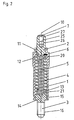
- Figures 1 to 3 show different embodiments of the invention electrical pressure contact with a housing sleeve 1, which is a contact facing (above in Figures 1 to 3) and a contact-facing end (below in Figures 1 to 3) has.
- the housing sleeve axis is designated by reference number 10.
- a contact pin 2 is mounted axially displaceably in the housing sleeve 1. Doing so he is biased by a coil spring 4 in the contact direction.
- the contact pin has a circumferential groove 11 in its circumferential surface, which is perpendicular is arranged to axis 10.
- a locking ring 6 sits with his contact-facing side (top in Figures 1 to 3) with a radially inward standing shoulder 12 of the housing sleeve can come into contact.
- locking ring 6 and housing sleeve shoulder 12 is the mobility of the contact pin in Contact direction limited.
- FIGS. 1 and 2 on the side of the locking ring 6 facing away from the contact Coil spring 4 on. At the end facing away from the contact, the housing sleeve 1 is through a connector 3 closed.
- This connector 3 is shown in FIG. 1 and 2 the coil spring 4 with its end facing away from the contact.
- the Connector 3 has a contact-facing first cylindrical section 13, whose diameter is slightly smaller than the inside diameter of the spring 4. In Figures 1 and 2, this first cylindrical portion 13 is inserted into the spring 4 and hold it in place.
- the connector 3 has a second cylindrical portion 14, the Diameter corresponds to the inner diameter of the housing sleeve 1.
- On his cylindrical peripheral surface is a circumferential notch 15.
- the Circumferential surface of the cylindrical section 14 with its circumferential notch 15 forms a crimping surface over which the housing sleeve 11 is crimped.
- At the Contact-away side of the cylindrical portion 14 includes an axial arranged threaded bolt 16 on which an electrical lead on itself known way can be attached.
- the biased contact pin 2 in the manner described can thus be a resilient Establish mechanical pressure contact with a counter contact.
- Examples of the pressure contact according to the invention are the contact pin 2 and that Connector 3 made of CuZn38Pb2. This material is sufficient conductive to make electrical contact via contact pin 2 and connector 3 manufacture.
- Contact pin 2 and connector 3 are axially flexible electrical line connected.
- the flexible electrical wire is braided Stranded hose made of copper.
- This stranded hose is in one end Bore 20 in contact pin 2 and the other end in a bore 21 in Inserted connector 3 and clamped in each of these.
- the corresponding sections of the contact pin 2 and the connector 3 with threaded stranded hose 5 pressed radially inwards, with a Pressure that is dimensioned so that the strand is clamped tight enough on the one hand that it cannot come loose and ensures good electrical contact, on the other hand is not damaged by the pressure.
- This type of attachment is called crimping.
- the pressure contact according to the invention differs from conventional ones Pressure contacts in which a cable or a strand on contact pin and Connector is soldered.
- the crimping of the wire offers one Solder the advantage that it is less expensive to manufacture, and the Lifetime of the pressure contact increased. Because there is a soldered strand Danger that it will unsolder if the pressure contact overheats. Besides, can the braid is stiffened by the solder, making it easier to break.
- the contact pin 2 When a pressure contact is in operation, the contact pin 2 is inserted into the housing sleeve 1 pushed, and the hose strand is axially compressed. Such an axial Compression can give the braided hose strand 5 optimally by itself fan out. This prevents the individual stranded fibers from being kinked and break, thereby increasing the life of the electric Pressure contact is increased.
- the braided tubular strand of the Pressure contact according to the invention is not required, which simplifies the construction makes and keeps the manufacturing costs lower. Because a braided one tubular strands can give way particularly well to axial compression, can be kept larger overall, i.e. a large number of stranded fibers included without being too stiff and therefore prone to breakage. Therefore, the Pressure contact according to the invention with a stranded hose, in particular for transmission high currents can be designed.
- the flexible electrical line between contact pin 2 and connector 3 alone through the coil spring 4 is formed, which simultaneously biases the contact pin 2.
- Fig. 3 Such electrical pressure contact is shown in Fig. 3.
- Contact pin 2 is on an axial bore 22 and the connector 3 on its side facing away from the contact an axial bore 23 on its contact-facing side. In these bores the ends of the spring 4 are inserted and with the contact pin or connector crimped.
- Such a structure is simple and long-lasting because the Spring 4 is insensitive to compression.
- the contact pin 2 has a rounded gold-plated contact surface 24. By the rounding can make good electrical contact with a via this contact surface Counter contact surface are formed, even if the contact pin 2 is not quite meets them vertically.
- the contact pin 2 with a silver rivet 7 be provided, which is shown in Figures 2 and 3.
- the silver rivet 7 has one Elongated section 25, with which it fits into an axial bore 26 in the contact pin 2 is used. It also has a head 27 with a contact facing bulging contact surface, which can also be gold-plated.
- the invention is distinguished electrical pressure contact through a simple construction from a few simple parts to be manufactured and assembled quickly and inexpensively.
- the contact pin in Figures 1 and 2 essentially has one cylindrical shape, which is shown in the figure only as a result of the crimping with the strand something is constricted. In particular, this does not require a two-part construction Sections of different diameters to provide a stop for the shoulder 12 to build.
- the connector 3 also enables the attachment of strand 5 and / or spring 4, closure of the housing sleeve 1 via the notch 15 provided cylindrical crimping surface and the connection of a lead via a Threaded bolt 16.
- the crimp connection shown in the figures between the second cylindrical portion 14 of the connector 3 and the Housing sleeve 1 is quick and inexpensive to manufacture and very robust.
- the housing sleeve 1 is also made of CuZn38Pb2, the inexpensive, machinable, conductive and crimpable and therefore one Fast, simple and inexpensive manufacture of the electrical according to the invention Pressure contact allowed.
Landscapes
- Coupling Device And Connection With Printed Circuit (AREA)
- Connector Housings Or Holding Contact Members (AREA)
- Connections Effected By Soldering, Adhesion, Or Permanent Deformation (AREA)
- Contacts (AREA)
- Details Of Connecting Devices For Male And Female Coupling (AREA)
Abstract
Description
- eine Gehäusehülse mit einem kontaktzugewandten und einem kontaktabgewandten Ende,
- einen in der Gehäusehülse axial verschiebbar gelagerten Kontaktstift, der aus dem kontaktzugewandten Ende der Gehäusehülse vorsteht, gegen die Vorspannkraft eines in der Gehäusehülse angeordneten Vorspannelementes in die Gehäusehülse einschiebbar ist und über dessen leitfähigen Körper der elektrische Kontakt herstellbar ist,
- ein Anschlußstück zur Befestigung einer elektrischen Zuleitung am kontaktabgewandten Ende der Gehäusehülse und
- eine in der Gehäusehülse angeordnete axial flexible elektrische Leitung zwischen Anschlußstück und Kontaktstift.
- Fig. 1
- einen Längsschnitt durch einen erfindungsgemäßen elektrischen Druckkontakt mit geflochtener Schlauchlitze und vergoldeter Kontaktfläche,
- Fig. 2
- einen Längsschnitt durch einen erfindungsgemäßen elektrischen Druckkontakt mit geflochtener Schlauchlitze und Kontaktniet aus Silber und
- Fig. 3
- einen Längsschnitt durch einen erfindungsgemäßen elektrischen Druckkontakt, bei dem die flexible elektrische Leitung zwischen Kontaktstift und Anschlußstück durch die den Kontaktstift vorspannende Schraubenfeder gebildet wird.
Claims (16)
- Elektrischer Druckkontakt, umfassenddadurch gekennzeichnet, daß die flexible elektrische Leitung mit ihrem kontaktzugewandten Ende in einer am kontaktabgewandten Ende des Kontaktstifts ausgebildeten axialen Bohrung (20) eingeklemmt ist und mit ihrem kontaktabgewandten Ende in einer am kontaktzugewandten Ende des Anschlußstückes ausgebildeten axialen Bohrung (21) eingeklemmt ist.eine Gehäusehülse (1) mit einem kontaktzugewandten und einem kontaktabgewandten Ende,einen in der Gehäusehülse (1) axial verschiebbar gelagerten Kontaktstift (2), der an der kontaktzugewandten Seite aus der Gehäusehülse (1) vorsteht, gegen die Vorspannkraft eines in der Gehäusehülse (1) angeordneten Vorspannelementes in die Gehäusehülse einschiebbar ist und über dessen leitfähigen Körper der elektrischer Kontakt herstellbar ist,ein Anschlußstück (3) zur Befestigung einer elektrischen Zuleitung am kontaktabgewandten Ende der Gehäusehülse (1) undeine in der Gehäusehülse (1) angeordnete axial flexible elektrische Leitung (4, 5) zwischen Anschlußstück (3) und Kontaktstift (2),
- Elektrischer Druckkontakt nach Anspruch 1, dadurch gekennzeichnet, daß die Vorspannvorrichtung (4) eine Schraubenfeder ist.
- Elektrischer Druckkontakt nach Anspruch 1 oder 2, dadurch gekennzeichnet, daß die flexible elektrische Leitung eine schlauchförmige Litze (5) ist.
- Elektrischer Druckkontakt nach Anspruch 3, dadurch gekennzeichnet, daß die schlauchförmige Litze (5) geflochten ist und aus Kupfer besteht.
- Elektrischer Druckkontakt nach Anspruch 2, dadurch gekennzeichnet, daß die flexible elektrische Leitung durch die Schraubenfeder (4) gebildet wird.
- Elektrischer Druckkontakt nach einem der Ansprüche 2 bis 4, dadurch gekennzeichnet, daß das Anschlußstück (3) einen kontaktzugewandten ersten zylindrischen Abschnitt (13) hat, der co-axial mit der Gehäusehülse angeordnet ist und in die Schraubenfeder (4) eingeführt ist.
- Elektrischer Druckkontakt nach einem der Ansprüche 2 bis 4, 6, dadurch gekennzeichnet, daß der Kontaktstift (2) in seiner Umfangsfläche eine umlaufende, senkrecht zur Stiftachse angeordnete Nut (11) hat, in der ein Sperring (6) untergebracht ist, der auf seiner kontaktzugewandten Seite einen Anschlag für eine am kontaktzugewandten Ende der Hülse radial nach innen stehende Schulter (12) und an seiner kontaktabgewandten Seite einen Anschlag für die Feder (4) bildet.
- Elektrischer Druckkontakt nach Anspruch 5, dadurch gekennzeichnet, daß der Kontaktstift (2) in seiner Umfangfläche eine umlaufende, senkrecht zur Stiftachse angeordnete Nut (11) hat, in der ein Sperring (6) untergebracht ist, der auf seiner kontaktzugewandten Seite einen Anschlag für eine am kontaktzugewandten Ende der Hülse (1) radial nach innen stehende Schulter (12) bildet.
- Elektrischer Druckkontakt nach einem der vorhergehenden Ansprüche, dadurch gekennzeichnet, daß das Anschlußstück (3) einen zweiten zylindrischen Abschnitt (14) hat, dessen Durchmesser dem Innendurchmesser der Gehäusehülse (1) entspricht und der eine Crimpfläche hat, über die die Gehäusehülse (1) gecrimpt ist.
- Elektrischer Druckkontakt nach Anspruch 9, dadurch gekennzeichnet, daß die Crimpfläche eine den zweiten zylindrischen Abschnitt (14) umlaufende Kerbe (15) hat.
- Elektrischer Druckkontakt nach Anspruch 9 oder 10, dadurch gekennzeichnet, daß das Anschlußstück (3) auf der kontaktabgewandten Seite des zweiten zylindrischen Abschnittes (14) einen axial angeordneten Gewindebolzen (16) zum Anschließen der elektrischen Zuleitung hat.
- Elektrischer Druckkontakt nach einem der vorhergehenden Ansprüche, dadurch gekennzeichnet, daß der Kontaktstift (2) eine kontaktzugewandte abgerundete Kontaktfläche (24) hat.
- Elektrischer Druckkontakt nach Anspruch 12, dadurch gekennzeichnet, daß die Kontaktfläche (24) vergoldet ist.
- Elektrischer Druckkontakt nach einem der Ansprüche 1 bis 12, dadurch gekennzeichnet, daß in das kontaktzugewandte Ende des Kontäktstifts (2) eine Kontaktniet (7) aus Silber eingesetzt ist.
- Elektrischer Druckkontakt nach Anspruch 14, dadurch gekennzeichnet, daß die Kontaktniet (7) eine vergoldete Kontaktfläche hat.
- Elektrischer Druckkontakt nach einem der vorhergehenden Ansprüche, dadurch gekennzeichnet, daß Gehäusehülse (1), Kontaktstift (2) und Anschlußstück (3) aus Messing mit einem geringen Bleianteil bestehen, insbesondere aus CuZn38Pb2.
Applications Claiming Priority (2)
| Application Number | Priority Date | Filing Date | Title |
|---|---|---|---|
| DE10143200A DE10143200A1 (de) | 2001-09-04 | 2001-09-04 | Elektrischer Druckkontakt |
| DE10143200 | 2001-09-04 |
Publications (2)
| Publication Number | Publication Date |
|---|---|
| EP1289072A2 true EP1289072A2 (de) | 2003-03-05 |
| EP1289072A3 EP1289072A3 (de) | 2003-12-03 |
Family
ID=7697600
Family Applications (1)
| Application Number | Title | Priority Date | Filing Date |
|---|---|---|---|
| EP02019670A Withdrawn EP1289072A3 (de) | 2001-09-04 | 2002-09-03 | Elektrischer Druckkontakt |
Country Status (6)
| Country | Link |
|---|---|
| US (1) | US6773312B2 (de) |
| EP (1) | EP1289072A3 (de) |
| CN (1) | CN1258787C (de) |
| BR (1) | BR0203625A (de) |
| DE (1) | DE10143200A1 (de) |
| PL (1) | PL203844B1 (de) |
Families Citing this family (51)
| Publication number | Priority date | Publication date | Assignee | Title |
|---|---|---|---|---|
| US7040902B2 (en) * | 2003-03-24 | 2006-05-09 | Che-Yu Li & Company, Llc | Electrical contact |
| CN2682639Y (zh) * | 2003-11-20 | 2005-03-02 | 上海莫仕连接器有限公司 | 压接式导电端子 |
| CN2682641Y (zh) * | 2003-11-20 | 2005-03-02 | 上海莫仕连接器有限公司 | 压接式导电端子 |
| DE102004033864A1 (de) * | 2004-07-13 | 2006-02-16 | Era-Contact Gmbh | Elektrischer Druckkontakt |
| US20060183373A1 (en) * | 2005-02-17 | 2006-08-17 | Finke Michael D | Connector including isolated conductive paths |
| US7154286B1 (en) * | 2005-06-30 | 2006-12-26 | Interconnect Devices, Inc. | Dual tapered spring probe |
| US20070018666A1 (en) * | 2005-07-22 | 2007-01-25 | Nasser Barabi | Spring contact pin for an IC chip tester |
| DE102005037789A1 (de) * | 2005-08-10 | 2007-02-15 | Era-Contact Gmbh | Steckverbinderanordnung zum Herstellen und Trennen mindestens einer elektrischen Verbindung mit einer weiteren komplementären Steckverbinderanordnung |
| US7311526B2 (en) | 2005-09-26 | 2007-12-25 | Apple Inc. | Magnetic connector for electronic device |
| US7351066B2 (en) | 2005-09-26 | 2008-04-01 | Apple Computer, Inc. | Electromagnetic connector for electronic device |
| US7429188B2 (en) * | 2006-07-03 | 2008-09-30 | Hon Hai Precision Ind. Co., Ltd. | Cable connector assembly with status indicator means |
| US7217142B1 (en) | 2006-07-03 | 2007-05-15 | Hon Hai Precision Ind. Co., Ltd. | Cable connector assembly with improved contacts |
| US7377822B1 (en) * | 2006-12-14 | 2008-05-27 | Lotes Co., Ltd. | Electrical connector |
| US7479794B2 (en) * | 2007-02-28 | 2009-01-20 | Sv Probe Pte Ltd | Spring loaded probe pin assembly |
| US7736156B2 (en) * | 2007-05-10 | 2010-06-15 | Apple Inc. | Connector assembly with improved solder tails |
| WO2009105784A2 (en) * | 2008-02-21 | 2009-08-27 | Melni Mark L | Electrical connectors and methods of manufacturing and using same |
| US8066525B2 (en) | 2008-02-21 | 2011-11-29 | Melni Mark L | Electrical connectors and methods of manufacturing and using same |
| US7841776B2 (en) | 2008-09-30 | 2010-11-30 | Apple Inc. | Magnetic connector with optical signal path |
| US9791634B2 (en) | 2008-09-30 | 2017-10-17 | Apple Inc. | Magnetic connector with optical signal path |
| US8493085B2 (en) * | 2009-03-27 | 2013-07-23 | Essai, Inc. | Spring contact pin for an ic test socket and the like |
| US9046568B2 (en) * | 2009-03-27 | 2015-06-02 | Essai, Inc. | Universal spring contact pin and IC test socket therefor |
| US8052427B2 (en) | 2009-04-01 | 2011-11-08 | GM Global Technology Operations LLC | Connector assembly for coupling an electric motor to a power source |
| WO2011056901A2 (en) | 2009-11-03 | 2011-05-12 | Mark L Melni | Electrical connectors and methods of manufacturing and using same |
| US8888500B2 (en) | 2011-06-30 | 2014-11-18 | Apple Inc. | Robust magnetic connector |
| US9065205B2 (en) | 2011-08-11 | 2015-06-23 | Apple Inc. | Connector insert having a cable crimp portion with protrusions and a receptacle having label in the front |
| US8523576B2 (en) | 2011-10-24 | 2013-09-03 | GM Global Technology Operations LLC | Connector for coupling an electric motor to a power source |
| US9570828B2 (en) * | 2012-10-03 | 2017-02-14 | Corad Technology Inc. | Compressible pin assembly having frictionlessly connected contact elements |
| US9831589B2 (en) | 2012-10-03 | 2017-11-28 | Corad Technology Inc. | Compressible pin assembly having frictionlessly connected contact elements |
| US8956193B2 (en) * | 2012-12-12 | 2015-02-17 | Intel Corporation | Helicoil spring backing socket |
| US9702680B2 (en) | 2013-07-18 | 2017-07-11 | Dynaenergetics Gmbh & Co. Kg | Perforation gun components and system |
| US20220258103A1 (en) | 2013-07-18 | 2022-08-18 | DynaEnergetics Europe GmbH | Detonator positioning device |
| CN106062303B (zh) | 2014-03-07 | 2019-05-14 | 德国德力能有限公司 | 用于将引爆器定位在射孔枪组件内的装置和方法 |
| JP6489749B2 (ja) * | 2014-03-17 | 2019-03-27 | コラド・テクノロジー・インコーポレーテッド | 摩擦なく接続された接触要素を有する圧縮性ピンアセンブリ |
| US11293736B2 (en) | 2015-03-18 | 2022-04-05 | DynaEnergetics Europe GmbH | Electrical connector |
| DE102015207958A1 (de) * | 2015-04-29 | 2016-11-03 | Te Connectivity Germany Gmbh | Kontaktanordnung und Hülse für eine Kontaktanordnung |
| DE112016004978B4 (de) * | 2015-10-28 | 2019-11-28 | Autonetworks Technologies, Ltd. | Anschluss |
| CN106099486B (zh) * | 2016-08-22 | 2019-11-26 | 深圳市华惠连接器有限公司 | 电连接器可伸缩接触件 |
| CN106653418A (zh) * | 2017-03-20 | 2017-05-10 | 江西顾特乐精藏科技有限公司 | 触控式自动耦合装置 |
| CN107240799B (zh) * | 2017-07-28 | 2023-07-21 | 中车青岛四方车辆研究所有限公司 | 电压力接触器 |
| CN110416771B (zh) * | 2018-04-27 | 2021-04-06 | 株洲中车时代半导体有限公司 | 一种能够调节行程的软连接结构 |
| US11808093B2 (en) | 2018-07-17 | 2023-11-07 | DynaEnergetics Europe GmbH | Oriented perforating system |
| US11339614B2 (en) | 2020-03-31 | 2022-05-24 | DynaEnergetics Europe GmbH | Alignment sub and orienting sub adapter |
| WO2021116336A1 (en) | 2019-12-10 | 2021-06-17 | DynaEnergetics Europe GmbH | Initiator head with circuit board |
| WO2021122797A1 (en) | 2019-12-17 | 2021-06-24 | DynaEnergetics Europe GmbH | Modular perforating gun system |
| US11988049B2 (en) | 2020-03-31 | 2024-05-21 | DynaEnergetics Europe GmbH | Alignment sub and perforating gun assembly with alignment sub |
| CN111551763B (zh) * | 2020-05-20 | 2022-05-03 | 贵州电网有限责任公司 | 一种电能表表箱插接座及其插接机构 |
| CN111551764B (zh) * | 2020-05-20 | 2022-04-29 | 贵州电网有限责任公司 | 一种新型电能表接线端子 |
| US11424573B2 (en) | 2020-09-24 | 2022-08-23 | Apple Inc. | Magnetic connectors with self-centering floating contacts |
| CN112832672B (zh) * | 2020-11-17 | 2023-05-02 | 中石化江钻石油机械有限公司 | 一种具有监测丝扣松动的井下动力钻具 |
| WO2022184732A1 (en) | 2021-03-03 | 2022-09-09 | DynaEnergetics Europe GmbH | Bulkhead and tandem seal adapter |
| US11713625B2 (en) | 2021-03-03 | 2023-08-01 | DynaEnergetics Europe GmbH | Bulkhead |
Citations (4)
| Publication number | Priority date | Publication date | Assignee | Title |
|---|---|---|---|---|
| FR2063662A5 (de) | 1969-10-24 | 1971-07-09 | Alsthom | |
| FR2545993A1 (fr) | 1983-05-11 | 1984-11-16 | Marechal Sepm | Contacts electriques elastiques a pression axiale |
| DE4317255C2 (de) | 1993-05-24 | 1996-01-18 | Dunkel Otto Gmbh | Elektrischer Druckkontakt für voll- oder halbautomatische Schienenfahrzeug-Kupplungen |
| EP0435408B1 (de) | 1989-11-17 | 1996-04-10 | FABEG GmbH | Federnder Druckkontakt |
Family Cites Families (5)
| Publication number | Priority date | Publication date | Assignee | Title |
|---|---|---|---|---|
| US2724096A (en) * | 1952-12-04 | 1955-11-15 | American Phenolic Corp | Spring loaded butt contact with internal contacting sleeve |
| US3813772A (en) * | 1970-06-30 | 1974-06-04 | Reynolds Metals Co | Method of forming steel supported aluminum overhead conductors |
| DE2723731A1 (de) | 1977-05-26 | 1978-11-30 | Bbc Brown Boveri & Cie | Federdruckkontakt |
| US4743201A (en) * | 1987-05-08 | 1988-05-10 | General Signal Corporation | Moveable electrical contact plunger |
| US5641315A (en) * | 1995-11-16 | 1997-06-24 | Everett Charles Technologies, Inc. | Telescoping spring probe |
-
2001
- 2001-09-04 DE DE10143200A patent/DE10143200A1/de not_active Withdrawn
-
2002
- 2002-08-23 US US10/226,401 patent/US6773312B2/en not_active Expired - Lifetime
- 2002-09-02 PL PL355831A patent/PL203844B1/pl not_active IP Right Cessation
- 2002-09-03 CN CNB021415897A patent/CN1258787C/zh not_active Expired - Fee Related
- 2002-09-03 BR BR0203625-8A patent/BR0203625A/pt not_active IP Right Cessation
- 2002-09-03 EP EP02019670A patent/EP1289072A3/de not_active Withdrawn
Patent Citations (4)
| Publication number | Priority date | Publication date | Assignee | Title |
|---|---|---|---|---|
| FR2063662A5 (de) | 1969-10-24 | 1971-07-09 | Alsthom | |
| FR2545993A1 (fr) | 1983-05-11 | 1984-11-16 | Marechal Sepm | Contacts electriques elastiques a pression axiale |
| EP0435408B1 (de) | 1989-11-17 | 1996-04-10 | FABEG GmbH | Federnder Druckkontakt |
| DE4317255C2 (de) | 1993-05-24 | 1996-01-18 | Dunkel Otto Gmbh | Elektrischer Druckkontakt für voll- oder halbautomatische Schienenfahrzeug-Kupplungen |
Also Published As
| Publication number | Publication date |
|---|---|
| CN1407570A (zh) | 2003-04-02 |
| PL355831A1 (en) | 2003-03-10 |
| US20030049974A1 (en) | 2003-03-13 |
| CN1258787C (zh) | 2006-06-07 |
| DE10143200A1 (de) | 2003-04-03 |
| US6773312B2 (en) | 2004-08-10 |
| BR0203625A (pt) | 2003-06-03 |
| EP1289072A3 (de) | 2003-12-03 |
| PL203844B1 (pl) | 2009-11-30 |
Similar Documents
| Publication | Publication Date | Title |
|---|---|---|
| EP1289072A2 (de) | Elektrischer Druckkontakt | |
| EP1776740B1 (de) | Elektrischer druckkontakt | |
| EP0491979A1 (de) | Herzschrittmacher-Katheter mit zwei Polen | |
| DE202007008404U1 (de) | Heizpatrone mit Kopplungselement | |
| EP2061119B1 (de) | Kontaktelement und Verfahren zur Herstellung eines Kontaktelementes | |
| DE2731001C3 (de) | Elektrische Steckkontaktbuchse | |
| DE102016107162A1 (de) | Elektrische Kontaktklemme und Verwendung einer solchen | |
| EP3361826A1 (de) | Heizpatrone | |
| EP3336969B1 (de) | Kontaktierungsvorrichtung zur elektrischen energieübertragung zu einer leiterplatte und verfahren zur montage einer derartigen kontaktierungsvorrichtung | |
| DE2550245A1 (de) | Anschlussklemme fuer eine vorrichtung oder ein element zur elektrischen verbindung | |
| EP0435408A2 (de) | Federnder Druckkontakt | |
| EP0968548B1 (de) | Steckerbuchse mit in der form eines hyperboloids angeordneten kontaktbereichen | |
| DE102010052627A1 (de) | Mantelleitungscrimpverbindung für Zug- und Druckentlastung einschließlich Schirmübertragung zur Metallhülse | |
| DE4300759C2 (de) | Lampenfassung | |
| DE1924076C3 (de) | Kontaktanordnung für elektrische Schalter | |
| WO2021160394A1 (de) | Kontaktelementbaugruppe für ein steckverbinderteil | |
| DE602004001419T2 (de) | Bürstenköcher mit konstanter Kraft | |
| DE2723731A1 (de) | Federdruckkontakt | |
| DE20121422U1 (de) | Kontakt zum Übertragen von elektrischem Strom | |
| DE602005004007T2 (de) | Verbesserter elektrischer Verbinder | |
| EP1109272B1 (de) | Kohlebürstenhalter | |
| DE10124532A1 (de) | Elektrische Steckverbindung | |
| AT411199B (de) | Kontakthülse für elektrische steckvorrichtungen | |
| DE2214988C3 (de) | Elektrische Anschlußbuchse | |
| EP0922314B1 (de) | Muttersteckerteil für elektrische steckverbinder |
Legal Events
| Date | Code | Title | Description |
|---|---|---|---|
| PUAI | Public reference made under article 153(3) epc to a published international application that has entered the european phase |
Free format text: ORIGINAL CODE: 0009012 |
|
| AK | Designated contracting states |
Kind code of ref document: A2 Designated state(s): AT BE BG CH CY CZ DE DK EE ES FI FR GB GR IE IT LI LU MC NL PT SE SK TR Designated state(s): AT BE BG CH CY CZ DE DK EE ES FI FR GB GR IE IT LI LU MC NL PT SE SK TR |
|
| AX | Request for extension of the european patent |
Extension state: AL LT LV MK RO SI |
|
| PUAL | Search report despatched |
Free format text: ORIGINAL CODE: 0009013 |
|
| AK | Designated contracting states |
Kind code of ref document: A3 Designated state(s): AT BE BG CH CY CZ DE DK EE ES FI FR GB GR IE IT LI LU MC NL PT SE SK TR |
|
| AX | Request for extension of the european patent |
Extension state: AL LT LV MK RO SI |
|
| 17P | Request for examination filed |
Effective date: 20040514 |
|
| AKX | Designation fees paid | ||
| RBV | Designated contracting states (corrected) |
Designated state(s): AT BE BG CH CY CZ DE DK EE ES FI FR GB GR IE IT LI LU MC NL PT SE SK TR |
|
| REG | Reference to a national code |
Ref country code: DE Ref legal event code: 8566 |
|
| 17Q | First examination report despatched |
Effective date: 20100827 |
|
| STAA | Information on the status of an ep patent application or granted ep patent |
Free format text: STATUS: THE APPLICATION IS DEEMED TO BE WITHDRAWN |
|
| 18D | Application deemed to be withdrawn |
Effective date: 20150401 |