US11713625B2 - Bulkhead - Google Patents
Bulkhead Download PDFInfo
- Publication number
- US11713625B2 US11713625B2 US17/677,478 US202217677478A US11713625B2 US 11713625 B2 US11713625 B2 US 11713625B2 US 202217677478 A US202217677478 A US 202217677478A US 11713625 B2 US11713625 B2 US 11713625B2
- Authority
- US
- United States
- Prior art keywords
- cover
- fixed body
- inner diameter
- electrical contact
- small region
- Prior art date
- Legal status (The legal status is an assumption and is not a legal conclusion. Google has not performed a legal analysis and makes no representation as to the accuracy of the status listed.)
- Active, expires
Links
Images


Classifications
-
- E—FIXED CONSTRUCTIONS
- E21—EARTH OR ROCK DRILLING; MINING
- E21B—EARTH OR ROCK DRILLING; OBTAINING OIL, GAS, WATER, SOLUBLE OR MELTABLE MATERIALS OR A SLURRY OF MINERALS FROM WELLS
- E21B17/00—Drilling rods or pipes; Flexible drill strings; Kellies; Drill collars; Sucker rods; Cables; Casings; Tubings
- E21B17/02—Couplings; joints
- E21B17/028—Electrical or electro-magnetic connections
- E21B17/0285—Electrical or electro-magnetic connections characterised by electrically insulating elements
-
- E—FIXED CONSTRUCTIONS
- E21—EARTH OR ROCK DRILLING; MINING
- E21B—EARTH OR ROCK DRILLING; OBTAINING OIL, GAS, WATER, SOLUBLE OR MELTABLE MATERIALS OR A SLURRY OF MINERALS FROM WELLS
- E21B17/00—Drilling rods or pipes; Flexible drill strings; Kellies; Drill collars; Sucker rods; Cables; Casings; Tubings
- E21B17/02—Couplings; joints
- E21B17/028—Electrical or electro-magnetic connections
-
- E—FIXED CONSTRUCTIONS
- E21—EARTH OR ROCK DRILLING; MINING
- E21B—EARTH OR ROCK DRILLING; OBTAINING OIL, GAS, WATER, SOLUBLE OR MELTABLE MATERIALS OR A SLURRY OF MINERALS FROM WELLS
- E21B33/00—Sealing or packing boreholes or wells
- E21B33/10—Sealing or packing boreholes or wells in the borehole
- E21B33/12—Packers; Plugs
- E21B33/1208—Packers; Plugs characterised by the construction of the sealing or packing means
Definitions
- Bulkheads may be used in wellbore tool strings to provide electrical connection between segments of the perforating tool string, and they may also provide a seal against fluid and/or pressure between segments of the wellbore tool string.
- Exemplary embodiments of bulkheads may use sealing elements, such as O-rings that are provided on either or both of an interior conductive body and an exterior bulkhead body, or bulkhead covers formed of a material capable of creating a fluid and/or pressure seal.
- sealing elements such as O-rings that are provided on either or both of an interior conductive body and an exterior bulkhead body, or bulkhead covers formed of a material capable of creating a fluid and/or pressure seal.
- a simplified bulkhead requiring less material and/or parts, as well as less expensive manufacturing methods for the constituent parts, while still allowing ease of use of the device in practical application.
- a bulkhead with dampening and/or shock absorption features to reduce damage to the wellbore perforating tool string and maintain electrical communication during wellbore operations.
- a bulkhead with a first electrical contact configured for connection to an up-hole tool, and a second electrical contact configured for electrical connection to a downhole tool.
- the exemplary embodiments include a bulkhead including a fixed body having a first contact surface and an exterior fixed body surface.
- a seal element may be provided on the exterior fixed body surface.
- the bulkhead may include a first electrical contact, a first spring having a first spring end in contact with the first contact surface, and a second spring end in contact with the first electrical contact.
- the bulkhead may further include a first cover having a first large region having a first large region inner diameter and a first small region having a first small region inner diameter, wherein the first large region inner diameter is larger than the first small region inner diameter.
- the bulkhead fixed body, the first electrical contact, and the first spring may be inserted through the first cover such that the first electrical contact protrudes through the first small region and a portion of the first large region surrounds a first fixed body portion of the fixed body.
- a first contact maximum outer diameter of the first electrical contact may be larger than the first small region inner diameter of the first small region.
- the exemplary embodiments include a bulkhead including a fixed body having an exterior fixed body surface.
- the bulkhead may further include a first cover having a first large region having a first large region inner diameter and a first small region having a first small region inner diameter, wherein the first large region inner diameter is larger than the first small region inner diameter, and a second cover having a first large region having a first large region inner diameter and a first small region having a first small region inner diameter, wherein the first large region inner diameter is larger than the first small region inner diameter.
- a seal element may be provided on the exterior fixed body surface in a gap provided between the first cover and the second cover.
- the bulkhead fixed body may further include a first contact protrusion that extends through the first small region of the first cover, and a second contact protrusion that extends through the second small region of the second cover.
- the exemplary embodiments include a tandem seal adapter (TSA), including a TSA body, a bore extending through the TSA body, and a bulkhead provided within the bore.
- the bulkhead may include a fixed body having an exterior fixed body surface, a cover surrounding a portion of the fixed body, a first electrical contact extending from a first end of the cover, a second electrical contact extending from a second end of the cover, and a seal element provided on the exterior fixed body surface. There may be one and only one seal element provided on the exterior fixed body surface.
- FIG. 1 is a cross section view of a bulkhead according to an exemplary embodiment
- FIG. 1 A is a partial cross section view of a bulkhead according to an exemplary embodiment
- FIG. 2 is a cross section view of a first cover and a first electrical contact according to an exemplary embodiment
- FIG. 3 is a cross section view of a first cover, a second cover, and a fixed body according to an exemplary embodiment
- FIG. 4 A is a cross section view of a tandem seal adapter according to an exemplary embodiment
- FIG. 4 B is a cross section view of a tandem seal adapter and bulkhead according to an exemplary embodiment
- FIG. 5 is a cross section view of a bulkhead according to an exemplary embodiment
- FIG. 6 is a cross section view of a bulkhead according to an exemplary embodiment
- FIG. 7 A is a partial cross section view of a first cover and a first electrical contact according to an exemplary embodiment
- FIG. 7 B is a partial cross section view of a second cover and a second electrical contact according to an exemplary embodiment
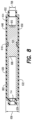
- FIG. 8 is a cross section view of a first cover, a second cover, and a fixed body according to an exemplary embodiment
- FIG. 9 A is a cross section view of a top connector tandem seal adapter according to an exemplary embodiment
- FIG. 9 B is a cross section view of a top connector tandem seal adapter and bulkhead according to an exemplary embodiment.
- FIG. 10 is a cross section view of a collar, a top connector tandem seal adapter, and a bulkhead according to an exemplary embodiment.
- FIG. 1 shows an exemplary embodiment of a bulkhead 102 .
- the bulkhead 102 may include a fixed body 104 , a seal element 116 , a first electrical contact 118 , a second electrical contact 136 , a first spring 124 , a second spring 142 , and a cover (i.e., a first cover 130 , and a second cover 148 ).
- the fixed body 104 may be formed of an electrically conductive material and may include a first contact surface 106 , a second contact surface 110 opposite to the first contact surface 106 , and an exterior fixed body surface 114 .
- the seal element 116 may be provided on the exterior fixed body surface 114 .
- a first chamfered edge 108 may be formed adjacent to the first contact surface 106 .
- a second chamfered edge may be provided adjacent to the second contact surface 110 .
- the first chamfered edge 108 and the second contact surface 110 may be rounded instead of chamfered.
- the first electrical contact 118 may be formed of an electrically conductive material, and may include a first contact hollow interior 120 and a first open end 122 .
- the second electrical contact 136 may be formed of an electrically conductive material, and may include a second contact hollow interior 138 and a second open end 140 .
- the first electrical contact 118 and the second electrical contact 136 may be formed by a deep drawn molding method or other suitable method that allows formation of a hollow part.
- the first electrical contact 118 and the second electrical contact 136 may be formed in any size, shape, or dimension suitable for providing an electrical connection to an adjacent electrically conductive component.
- the first electrical contact 118 may be formed with a flattened hollow tip. In an exemplary embodiment shown in FIG.
- the first electrical contact 118 ′ may be formed with a pointed hollow tip.
- the size, shape, or dimension of the first electrical contact 118 and the second electrical contact 136 are not limited to these examples, and that other sizes, shapes, or dimensions are possible.
- the first spring 124 may be formed of an electrically conductive material. A first spring end 126 of the first spring 124 may be in contact with the first contact surface 106 of the fixed body 104 . The first spring 124 may extend through the first open end 122 of the first electrical contact 118 such that a second spring end 128 of the first spring 124 may be in contact with the first electrical contact 118 within the first contact hollow interior 120 .
- the second spring 142 may be formed of an electrically conductive material.
- a third spring end 144 of the second spring 142 may be in contact with the second contact surface 110 of the fixed body 104 .
- the second spring 142 may extend through the second open end 140 of the second electrical contact 136 such that a fourth spring end 146 of the second spring 142 may be in contact with the second electrical contact 136 within the second contact hollow interior 138 .
- the first electrical contact 118 , the first spring 124 , the fixed body 104 , the second spring 142 , and the second electrical contact 136 may be in mutual electrical communication with each other.
- the first cover 130 may include a first large region 132 having a first large region inner diameter 202 and a first small region 134 having a first small region inner diameter 204 (see FIG. 3 ). As further seen in FIG. 2 , the first large region inner diameter 202 may be larger than the first small region inner diameter 204 .
- the first cover 130 may be formed of an electrically non-conductive material such as plastic, ceramic, glass, wood, thermoplastic, or other suitable non-conductive material. In an aspect, the first cover 130 may be formed of a polyamide material, for example, Polyamide 6, Nylon 6, or polycaprolactam (PA6).
- the second cover 148 may include a second large region 150 having a second large region inner diameter and a second small region 152 having a second small region inner diameter. Similar to the relationship illustrated between the first large region inner diameter 202 and the first small region inner diameter 204 in FIGS. 2 and 3 , the second large region inner diameter may be larger than the second small region inner diameter.
- the second cover 148 may be formed of an electrically non-conductive material such as plastic, ceramic, glass, wood, thermoplastic, or other suitable non-conductive material. In an aspect, the second cover 148 may be formed of a polyamide material, for example, Polyamide 6, Nylon 6, or polycaprolactam (PA6).
- the first cover 130 and the second cover 148 may be fixed to the fixed body 104 .
- the first cover 130 and the second cover 148 may be press fit to the fixed body 104 , attached to the fixed body 104 via a glue, epoxy, or other adhesive, or threadedly engaged with the fixed body 104 via mutually complementary threads.
- the affixation of the first cover 130 and the second cover 148 to the fixed body 104 are not limited to these examples, and that other methods of affixation are possible.
- FIG. 1 further shows that there may be a gap 154 between the first cover 130 and the second cover 148 through which the seal element 116 may protrude.
- the first cover 130 and the second cover 148 may prevent flow or movement of the seal element 116 .
- the first cover 130 and the second cover 148 may help to maintain the seal element 116 in the proper position.
- first cover 130 and the second cover 148 is not intended to be limited in terms of the composition or number of parts in the structure(s) surrounding the fixed body 104 .
- first cover 130 and the second cover 148 may be collectively referred to as a single cover.
- first cover 130 and the second cover 148 may be replaced by a single cover.
- the seal element 116 may protrude through the gap 154 in the cover.
- the fixed body 104 , the first electrical contact 118 , and the first spring 124 may be inserted through the first cover 130 such that the first electrical contact 118 protrudes through the first small region 134 of the first cover 130 .
- a portion of the first large region 132 may surround a first fixed body portion 302 of the fixed body 104 (see FIG. 3 ).
- the fixed body 104 , the second electrical contact 136 , and the second spring 142 may be inserted through the second cover 148 such that the second electrical contact 136 protrudes through the second small region 152 of the second cover 148 .
- a portion of the second large region 150 may surround a second fixed body portion 304 of the fixed body 104 (see FIG. 3 ).
- a third fixed body portion 306 of the fixed body 104 may be provided between the first fixed body portion 302 and the second fixed body portion 304 .
- the third fixed body portion 306 may be formed of a solid piece of electrically conductive material configured to provide an electrical connection between the first contact surface 106 and the second contact surface 110 .
- the seal element 116 may be provided on the exterior fixed body surface 114 defined by the third fixed body portion 306 .
- the first electrical contact 118 may have a first contact maximum outer diameter 206 .
- the first contact maximum outer diameter 206 may be larger than the first small region inner diameter 204 .
- the second electrical contact 136 may have a second contact maximum outer diameter. Similar to the relationship between the first small region inner diameter 204 and the first contact maximum outer diameter 206 shown in FIG. 2 , the second contact maximum outer diameter may be larger than the second small region inner diameter.
- the second electrical contact 136 may be retained within the second cover 148 .
- the first contact maximum outer diameter 206 may be the same as or different (i.e., smaller or larger) than the second contact maximum outer diameter.
- FIG. 4 A and FIG. 4 B show an exemplary embodiment of a tandem seal adapter (TSA) 402 .
- the tandem seal adapter 402 may include a TSA body 404 and a bore 406 extending through the TSA body 404 .
- the bulkhead 102 may be provided within the bore 406 .
- the TSA body 404 may include a first body portion 408 having a first bore inner diameter 412 and a second body portion 410 having a second bore inner diameter 414 .
- the second bore inner diameter 414 may be larger than the first bore inner diameter 412 .
- the first large region 132 of the first cover 130 and the second large region 150 of the second cover 148 see FIG.
- the bulkhead 102 may be retained within the TSA body 404 .
- the seal element 116 of the bulkhead 102 may be in contact with the TSA body 404 (i.e., with the second body portion 410 ) in order to form a seal that prevents transfer of fluid and/or pressure through the tandem seal adapter 402 .
- the bulkhead 102 may be secured in the tandem seal adapter 402 via a retainer nut 416 or other suitable structure.
- FIG. 5 shows another exemplary embodiment of a bulkhead 502 .
- the bulkhead 502 may include a fixed body 504 , the seal element 116 , the first cover 130 , and the second cover 148 .
- the fixed body 504 may be formed of a conductive material as an integral and monolithic piece extending through the bulkhead 502 .
- the fixed body 504 may include an exterior fixed body surface 506 , and the seal element 116 may be provided on the exterior fixed body surface 506 in a gap 154 formed between the first cover 130 and the second cover 148 .
- the fixed body 504 may further include a first contact protrusion 508 that extends through the first small region 134 of the first cover 130 and a second contact protrusion 510 that extends through the second small region 152 of the second cover 148 .
- a portion of the first large region 132 of the first cover 130 may surround a first fixed body portion 514 of the fixed body 504
- a portion of the second large region 150 of the second cover 148 may surround a second fixed body portion 516 of the fixed body 504 .
- the fixed body 504 may have a fixed body maximum diameter 512 that is larger than the first small region inner diameter 204 (see FIG. 2 ) and the second small region inner diameter.
- the fixed body 504 , the first contact protrusion 508 , and the second contact protrusion 510 may be considered as separate components, i.e., as a first electrical contact, the fixed body 504 , and a second electrical contact, all in mutual electrical communication with each other, and providing electrical communication through the bulkhead 502 .
- FIG. 6 shows an exemplary embodiment of a bulkhead 602 .
- the bulkhead 602 may include a fixed body 604 , a seal element 616 , a first electrical contact 618 , a second electrical contact 636 , a first spring 624 , a second spring 642 , and a cover (i.e., a first cover 630 , and a second cover 648 ).
- the fixed body 604 may be formed of an electrically conductive material and may include a first contact surface 606 , a second contact surface 610 opposite to the first contact surface 606 , and an exterior fixed body surface 614 .
- the seal element 616 may be provided on the exterior fixed body surface 614 .
- the first contact surface 606 may be provided as a flat, planar surface with no adjacent chamfering or curvature such that the first contact surface 606 is perpendicular to a neighboring inner wall of the fixed body 604 .
- a chamfered edge 608 may be provided adjacent to the second contact surface 610 .
- one or each of the first contact surface 606 and the second contact surface 610 may be formed as a flat, planar surface.
- a chamfered edge may be formed adjacent to the first contact surface 606 .
- one or each of the first contact surface 606 and the second contact surface 610 may be rounded or curved.
- the first electrical contact 618 may be formed of an electrically conductive material, and may be formed as a solid, monolithic component.
- the first electrical contact 618 may be formed by machining processes such as computerized numerical control (CNC) machining, 3-D milling, or other metal machine processes.
- the first electrical contact 618 may include a first contact body 620 and a first contact end 622 and be configured such that the first electrical contact 618 , the first spring 624 , and the fixed body 604 are in mutual electrical communication with each other.
- the first spring 624 may be formed of an electrically conductive material. A first spring end 626 of the first spring 624 may be in contact with the first contact surface 606 of the fixed body 604 .
- the first spring 624 may be positioned to receive and retain the first contact end 622 of the first electrical contact 618 within an interior space of the first spring 624 such that a second spring end 628 of the first spring 624 may be in contact with the first electrical contact 618 within an interior space of the fixed body 604 . It will be understood that the depiction of the first electrical contact 618 is not intended to be limited in terms of the size, shape, or dimension of the first electrical contact 618 .
- the first contact end 622 may be a flat surface, or may be formed with an opening in which the second spring end 628 is received.
- the size, shape, or dimension of the first electrical contact 618 is not limited to these examples, and that other sizes, shapes, or dimensions are possible.
- the second electrical contact 636 may be formed of an electrically conductive material, and may include a second contact hollow interior 638 and a second contact open end 640 .
- the second electrical contact 636 may be formed by a deep drawn molding method or other suitable method that allows formation of a hollow part.
- the second spring 642 may be formed of an electrically conductive material.
- a third spring end 644 of the second spring 642 may be in contact with the second contact surface 610 of the fixed body 604 .
- the second spring 642 may extend through the second contact open end 640 of the second electrical contact 636 such that a fourth spring end 646 of the second spring 642 may be in contact with the second electrical contact 636 within the second contact hollow interior 638 .
- the first electrical contact 618 , the first spring 624 , the fixed body 604 , the second spring 642 , and the second electrical contact 636 may be in mutual electrical communication with each other.
- the first cover 630 and the second cover 648 may be fixed to the fixed body 604 .
- the first cover 630 and the second cover 648 may be press fit to the fixed body 604 , attached to the fixed body 604 via a glue, epoxy, or other adhesive, or threadedly engaged with the fixed body 604 via mutually complementary threads.
- the affixation of the first cover 630 and the second cover 648 to the fixed body 604 are not limited to these examples, and that other methods of affixation are possible.
- FIG. 6 further shows that there may be a gap 654 between the first cover 630 and the second cover 648 through which the seal element 616 may protrude.
- the first cover 630 and the second cover 648 may prevent flow or movement of the seal element 616 .
- the first cover 630 and the second cover 648 may help to maintain the seal element 616 in the proper position.
- first cover 630 and the second cover 648 is not intended to be limited in terms of the composition or number of parts in the structure(s) surrounding the fixed body 604 .
- first cover 630 and the second cover 648 may be collectively referred to as a single cover.
- first cover 630 and the second cover 648 may be replaced by a single cover.
- the seal element 616 may protrude through the gap 654 in the cover.
- the first cover 630 may include a first large region 632 having a first large region inner diameter 702 and a first small region 634 having a first small region inner diameter 704 (see FIG. 8 ).
- the first large region inner diameter 702 may be larger than the first small region inner diameter 704 .
- the first cover 630 may be formed of an electrically non-conductive material such as plastic, ceramic, glass, wood, thermoplastic, or other suitable non-conductive material.
- the first cover 630 may be formed of a polyamide material, for example, Polyamide 6, Nylon 6, or polycaprolactam (PA6).
- the second cover 648 may include a second large region 650 having a second large region inner diameter 700 and a second small region 652 having a second small region inner diameter 708 (see FIG. 8 ). Similar to the relationship illustrated between the first large region inner diameter 702 and the first small region inner diameter 704 in FIGS. 7 A and 8 , the second large region inner diameter 700 may be larger than the second small region inner diameter 708 .
- the second cover 648 may be formed of an electrically non-conductive material such as plastic, ceramic, glass, wood, thermoplastic, or other suitable non-conductive material. In an aspect, the second cover 648 may be formed of a polyamide material, for example, Polyamide 6, Nylon 6, or polycaprolactam (PA6).
- the first large region inner diameter 702 may be the same as or different (i.e., smaller or larger) than the second large region inner diameter 700 .
- the first small region inner diameter 704 may be the same as or different (i.e., smaller or larger) than the second small region inner diameter 708 .
- the first electrical contact 618 may have a first contact maximum outer diameter 706 .
- the first contact maximum outer diameter 706 may be larger than the first small region inner diameter 704 .
- the second electrical contact 636 may have a second contact maximum outer diameter 710 .
- the second contact maximum outer diameter 710 may be larger than the second small region inner diameter 708 .
- the second electrical contact 636 may be retained within the second cover 648 .
- the first contact maximum outer diameter 706 may be the same as or different (i.e., smaller or larger) than the second contact maximum outer diameter 710 .
- the fixed body 604 , the first electrical contact 618 , and the first spring 624 may be inserted through the first cover 630 such that the first electrical contact 618 protrudes through the first small region 634 on a first end of the cover 630 .
- a portion of the first large region 632 may surround a first fixed body portion 802 of the fixed body 604 (see FIG. 8 ).
- the fixed body 604 , the second electrical contact 636 , and the second spring 642 may be inserted through the second cover 648 such that the second electrical contact 636 protrudes through the second small region 652 on a second end of the cover 648 .
- a portion of the second large region 650 may surround a second fixed body portion 804 of the fixed body 604 (see FIG.
- a third fixed body portion 806 of the fixed body 604 may be provided between the first fixed body portion 802 and the second fixed body portion 804 .
- the third fixed body portion 806 may be formed of a solid piece of electrically conductive material configured to provide an electrical connection between the first contact surface 606 and the second contact surface 610 .
- the sealing element 616 may be provided on the exterior fixed body surface 614 defined by the third fixed body portion 806 .
- FIG. 9 A and FIG. 9 B show an exemplary embodiment of a top connector tandem seal adapter (TSA) 902 that may be used as a top connector for electrical connection of a perforating gun to a tool string.
- the TSA or top connector 902 may include a TSA body 904 and a bore 906 extending through the TSA body 904 .
- the bulkhead 602 may be provided within the bore 906 .
- the TSA body 904 may include a first body portion 908 having a first bore inner diameter 914 and a second body portion 910 having a second bore inner diameter 916 .
- the second bore inner diameter 916 may be larger than the first bore inner diameter 914 .
- the seal element 616 of the bulkhead 602 may be in contact with the TSA body 904 (i.e., with the second body portion 910 ) in order to form a seal that prevents transfer of fluid and/or pressure through the tandem seal adapter 902 .
- the first cover 630 and the second cover 648 may have a cover maximum outer diameter 656 (see FIG. 8 ).
- the cover maximum outer diameter 656 may be larger than the first bore inner diameter 914 .
- the bulkhead 602 may be retained within the TSA body 904 .
- the bulkhead 602 may be secured in the tandem seal adapter 902 via a retainer nut 918 or other suitable structure.
- FIG. 10 shows an exemplary embodiment of a bulkhead 602 secured within a tandem seal adapter 902 that is in turn retained in a collar 1002 .
- the collar 1002 may include a collar body 1004 , a collar bore 1006 extending through collar body 1004 , and a collar open end 1008 .
- the TSA body 904 may include a maximum outer diameter portion 912 (see FIG. 9 A ) that is larger than a collar inner diameter 1010 defined by the collar bore 1006 .
- the tandem seal adapter 902 is retained within the collar 1002 .
- the second electrical contact 636 may be positioned adjacent to the collar open end 1008 for electrical contact and connection to an adjacent electrically conductive component.
- the collar open end 1008 may be configured for connection to an adjacent wireline tool, such as a wireline release tool.
- the collar open end 1008 may include a threaded interior portion 1012 for engagement with an adjacent wireline tool via mutually complementary threads.
- FIG. 1 illustrates embodiments with one seal element 116 , 616 .
- there will be one and only one seal element 116 , 616 with no other seal elements provided elsewhere on the bulkhead 102 , 502 , 602 .
- an exemplary embodiment may have more than one seal element 116 , 616 , provided on the exterior fixed body surface 114 , 506 , 614 of the fixed body 104 , 504 , 604 .
- An exemplary embodiment with one and only one seal element 116 , 616 may be advantageous in that it can reduce manufacturing costs due to the reduced number of components compared to devices with multiple seal elements. Additionally, using one and only one seal element 116 , 616 reduces the possible points of failure from a hydraulic sealing point of view.
- the embodiments described above may provide a number of benefits over conventional devices. For example, by placing the seal element 116 , 616 directly on the fixed body 104 , 604 and protruding through the gap 154 , 654 , the total number of required sealing elements can be reduced, as compared with conventional devices in which sealing elements may be provided on both an interior conductive body and an exterior bulkhead body. This may help to reduce the overall length of the bulkhead 102 , 602 , as well as reduce manufacturing costs.
- first cover 130 and the second cover 148 may not be directly involved with the sealing function of the bulkhead 102 , a wider range of materials can be used in making the first cover 130 and the second cover 148 . This allows for the selection of cost-effective materials to reduce the overall cost of the bulkhead 102 .
- the embodiments provided above may be used for electrical connection to various wireline tools to provide a wireline tool string including a bulkhead 102 , 502 , 602 and tandem seal adapter 402 , and/or top connector tandem seal adapter 902 , in which a first wireline tool is electrically connected to the first electrical contact 118 , 508 , 618 and a second wireline tool is electrically connected to the second electrical contact 136 , 510 , 636 .
- the solid first electrical contact 618 may formed of a size, shape, and dimension that conforms to an industry standard shape, size, or dimension that is well-known for electrical connection with a range of commercially available wellbore tools.
- the bulkhead 602 may be provided in a wireline tool string top connector tandem seal adapter (e.g., 902 ) for electrical connection to, for example, a casing collar locator (CCL).
- the first electrical contact 618 may be oriented up-hole in a tool string to connect to an adjacent up-hole tool, while the second electrical contact 636 may be oriented to electrically connect to a detonator head or another adjacent down-hole tool.
- the first contact hollow interior 120 provided in the first electrical contact 118 and the second contact hollow interior 138 provided in the second electrical contact 136 allow for a longer travel distance of the first spring 124 and the second spring 142 . This increases the dampening effect of the first spring 124 and the second spring 142 , especially after the firing of a perforating gun. Additionally, manufacturing costs can be reduced because of the reduced costs associated with the deep drawn method used for making the first electrical contact 118 and the second electrical contact 136 .
- the hollow structure of the first electrical contact 118 and the second electrical contact 136 due to the deep drawn material or non-solid material may allow for a significant collapsible or deformable zone around the first electrical contact 118 and the second electrical contact 136 . This may provide significant advantages in that shock impact and potential mechanical damage to a detonator head or other contacting components can be reduced or eliminated. Further, the first chamfered edge 108 and the second chamfered edge 112 may allow the inner ends of the first electrical contact 118 and the second electrical contact 136 to deform in the case of a shock during the firing of perforation guns, thereby improving a dampening effect.
- the profile of the end pin of the first electrical contact 118 and/or the second electrical contact 136 may be flattened. In other embodiments (e.g., FIG. 1 A ), the profile of the end pin of the first electrical contact and/or the second electrical contact 136 may be pointed.
- a flattened end pin profile may be advantageous in general applications.
- a pointed end pin profile may be advantageous in applications in which it is desirable to reduce rotational surface friction by the first electrical contact or the second electrical contact against the opposing electrode in an adjacent component to which the first electrical contact or the second electrical contact is electrically connected. This may include, for example, internally rotating or swiveling self-orienting perforating gun systems.
- first contact protrusion 508 and the second contact protrusion 510 of the bulkhead 502 may be configured for electrical connection to an adjacent wireline tool or component that includes its own respective spring-loaded contact.
- the solid, non-spring-loaded design of the bulkhead fixed body 504 requires connection to an opposite spring-loaded contact, such as a spring-loaded end plate or spring-loaded detonator, as described in U.S. Pat. No. 10,188,990, which is commonly owned by DynaEnergetics Europe GmbH and incorporated herein by reference.
- This disclosure in various embodiments, configurations and aspects, includes components, methods, processes, systems, and/or apparatuses as depicted and described herein, including various embodiments, sub-combinations, and subsets thereof.
- This disclosure contemplates, in various embodiments, configurations and aspects, the actual or optional use or inclusion of, e.g., components or processes as may be well-known or understood in the art and consistent with this disclosure though not depicted and/or described herein.
- each of the expressions “at least one of A, B and C,” “at least one of A, B, or C,” “one or more of A, B, and C,” “one or more of A, B, or C,” and “A, B, and/or C” means A alone, B alone, C alone, A and B together, A and C together, B and C together, or A, B, and C together.
- a value modified by a term such as “about” is not to be limited to the precise value specified. In some instances, the approximating language may correspond to the precision of an instrument for measuring the value. Terms such as “first,” “second,” “upper,” “lower,” etc. are used to identify one element from another, and unless otherwise specified are not meant to refer to a particular order or number of elements.
- the terms “may” and “may be” indicate a possibility of an occurrence within a set of circumstances; a possession of a specified property, characteristic or function; and/or qualify another verb by expressing one or more of an ability, capability, or possibility associated with the qualified verb. Accordingly, usage of “may” and “may be” indicates that a modified term is apparently appropriate, capable, or suitable for an indicated capacity, function, or usage, while taking into account that in some circumstances the modified term may sometimes not be appropriate, capable, or suitable. For example, in some circumstances an event or capacity can be expected, while in other circumstances the event or capacity cannot occur—this distinction is captured by the terms “may” and “may be.”
- the word “comprises” and its grammatical variants logically also subtend and include phrases of varying and differing extent such as for example, but not limited thereto, “consisting essentially of” and “consisting of.” Where necessary, ranges have been supplied, and those ranges are inclusive of all sub-ranges therebetween. It is to be expected that the appended claims should cover variations in the ranges except where this disclosure makes clear the use of a particular range in certain embodiments.
Landscapes
- Engineering & Computer Science (AREA)
- Life Sciences & Earth Sciences (AREA)
- Geology (AREA)
- Mining & Mineral Resources (AREA)
- Physics & Mathematics (AREA)
- Environmental & Geological Engineering (AREA)
- Fluid Mechanics (AREA)
- General Life Sciences & Earth Sciences (AREA)
- Geochemistry & Mineralogy (AREA)
- Mechanical Engineering (AREA)
- Connector Housings Or Holding Contact Members (AREA)
Abstract
Description
Claims (19)
Priority Applications (8)
| Application Number | Priority Date | Filing Date | Title |
|---|---|---|---|
| US17/677,478 US11713625B2 (en) | 2021-03-03 | 2022-02-22 | Bulkhead |
| PCT/EP2022/055014 WO2022184654A1 (en) | 2021-03-03 | 2022-02-28 | Modular perforating gun system |
| PCT/EP2022/055192 WO2022184732A1 (en) | 2021-03-03 | 2022-03-01 | Bulkhead and tandem seal adapter |
| PCT/EP2022/055191 WO2022184731A1 (en) | 2021-03-03 | 2022-03-01 | Orienting perforation gun assembly |
| US18/166,310 US11732556B2 (en) | 2021-03-03 | 2023-02-08 | Orienting perforation gun assembly |
| US18/327,451 US12338718B2 (en) | 2021-03-03 | 2023-06-01 | Orienting perforation gun assembly |
| US18/336,830 US12091919B2 (en) | 2021-03-03 | 2023-06-16 | Bulkhead |
| US19/194,775 US20250270905A1 (en) | 2021-03-03 | 2025-04-30 | Orienting perforation gun assembly |
Applications Claiming Priority (2)
| Application Number | Priority Date | Filing Date | Title |
|---|---|---|---|
| US202163155902P | 2021-03-03 | 2021-03-03 | |
| US17/677,478 US11713625B2 (en) | 2021-03-03 | 2022-02-22 | Bulkhead |
Related Child Applications (2)
| Application Number | Title | Priority Date | Filing Date |
|---|---|---|---|
| PCT/EP2022/055191 Continuation-In-Part WO2022184731A1 (en) | 2021-03-03 | 2022-03-01 | Orienting perforation gun assembly |
| US18/336,830 Continuation US12091919B2 (en) | 2021-03-03 | 2023-06-16 | Bulkhead |
Publications (2)
| Publication Number | Publication Date |
|---|---|
| US20220282578A1 US20220282578A1 (en) | 2022-09-08 |
| US11713625B2 true US11713625B2 (en) | 2023-08-01 |
Family
ID=83116992
Family Applications (1)
| Application Number | Title | Priority Date | Filing Date |
|---|---|---|---|
| US17/677,478 Active 2042-02-22 US11713625B2 (en) | 2021-03-03 | 2022-02-22 | Bulkhead |
Country Status (1)
| Country | Link |
|---|---|
| US (1) | US11713625B2 (en) |
Cited By (5)
| Publication number | Priority date | Publication date | Assignee | Title |
|---|---|---|---|---|
| US20230046639A1 (en) * | 2021-08-12 | 2023-02-16 | Schlumberger Technology Corporation | Pressure bulkhead |
| US12241341B2 (en) | 2022-07-27 | 2025-03-04 | Schlumberger Technology Corporation | Detonation module |
| US12338718B2 (en) | 2021-03-03 | 2025-06-24 | DynaEnergetics Europe GmbH | Orienting perforation gun assembly |
| USD1082873S1 (en) | 2021-05-13 | 2025-07-08 | XConnect, LLC | Tandem sub for a roller bearing |
| US12366142B2 (en) | 2021-03-03 | 2025-07-22 | DynaEnergetics Europe GmbH | Modular perforating gun system |
Families Citing this family (5)
| Publication number | Priority date | Publication date | Assignee | Title |
|---|---|---|---|---|
| US11293736B2 (en) * | 2015-03-18 | 2022-04-05 | DynaEnergetics Europe GmbH | Electrical connector |
| US11661824B2 (en) | 2018-05-31 | 2023-05-30 | DynaEnergetics Europe GmbH | Autonomous perforating drone |
| US12410690B2 (en) | 2021-12-09 | 2025-09-09 | XConnect, LLC | Orienting perforating gun system, and method of orienting shots in a perforating gun assembly |
| US12509971B2 (en) | 2023-04-20 | 2025-12-30 | XConnect , LLC | Roller bearing assembly, and method of grounding a perforating gun assembly |
| US12442278B2 (en) | 2023-04-20 | 2025-10-14 | XConnect , LLC | Tandem sub for a perforating gun assembly |
Citations (424)
| Publication number | Priority date | Publication date | Assignee | Title |
|---|---|---|---|---|
| US2216359A (en) | 1939-05-22 | 1940-10-01 | Lane Wells Co | Gun perforator for oil wells |
| US2228873A (en) | 1939-08-30 | 1941-01-14 | Du Pont | Electric blasting initiator |
| US2296346A (en) | 1941-07-03 | 1942-09-22 | Bell Telephone Labor Inc | Electrical terminal |
| US2326406A (en) | 1942-08-18 | 1943-08-10 | Lane Wells Co | Gun perforator |
| US2358466A (en) | 1940-09-12 | 1944-09-19 | Herbert C Otis | Well tool |
| US2418486A (en) | 1944-05-06 | 1947-04-08 | James G Smylie | Gun perforator |
| US2439394A (en) | 1945-07-04 | 1948-04-13 | Us Sec War | Grommet insulating bushing unit |
| US2519116A (en) | 1948-12-28 | 1950-08-15 | Shell Dev | Deformable packer |
| US2543814A (en) | 1946-12-26 | 1951-03-06 | Welex Jet Services Inc | Means and method of tilting explosive charges in wells |
| US2598651A (en) | 1946-07-01 | 1952-05-27 | Thomas C Bannon | Gun perforator |
| US2655993A (en) | 1948-01-22 | 1953-10-20 | Thomas C Bannon | Control device for gun perforators |
| US2696258A (en) | 1950-05-15 | 1954-12-07 | Haskell M Greene | Oil well cementing packer |
| US2734456A (en) | 1956-02-14 | sweetman | ||
| US2785631A (en) | 1950-10-05 | 1957-03-19 | Borg Warner | Shaped explosive-charge perforating apparatus |
| US2821136A (en) | 1951-04-05 | 1958-01-28 | P G A C Dev Co | Firing system for jet type perforating gun |
| US2889775A (en) | 1955-02-21 | 1959-06-09 | Welex Inc | Open hole perforator firing means |
| US2906339A (en) | 1954-03-30 | 1959-09-29 | Wilber H Griffin | Method and apparatus for completing wells |
| US2946283A (en) | 1955-09-02 | 1960-07-26 | Borg Warner | Method and apparatus for perforating wellbores and casings |
| US2982210A (en) | 1958-06-25 | 1961-05-02 | Ensign Bickford Co | Connecting cord |
| US3040659A (en) | 1958-05-12 | 1962-06-26 | Otis J Mcculleugh | Well perforating device |
| USRE25407E (en) | 1963-06-25 | Method and apparatus for detonating | ||
| US3125024A (en) | 1964-03-17 | Explosive connecting cord | ||
| US3155164A (en) | 1961-01-10 | 1964-11-03 | Jet Set Corp | Means for setting tubular bodies |
| US3158680A (en) | 1962-02-01 | 1964-11-24 | Gen Telephone & Electronies Co | Telephone cable system |
| US3170400A (en) | 1960-11-23 | 1965-02-23 | Atlas Chem Ind | Detonating means securing device |
| US3173992A (en) | 1962-11-16 | 1965-03-16 | Technical Drilling Service Inc | Resilient, high temperature resistant multiple conductor seal for conical ports |
| USRE25846E (en) | 1965-08-31 | Well packer apparatus | ||
| US3246707A (en) | 1964-02-17 | 1966-04-19 | Schlumberger Well Surv Corp | Selective firing system |
| US3264989A (en) | 1964-03-06 | 1966-08-09 | Du Pont | Ignition assembly resistant to actuation by radio frequency and electrostatic energies |
| US3264994A (en) | 1963-07-22 | 1966-08-09 | Baker Oil Tools Inc | Subsurface well apparatus |
| US3336054A (en) | 1965-01-15 | 1967-08-15 | Mobil Oil Corp | Liner-carrying well pipe and joint |
| US3374735A (en) | 1966-09-29 | 1968-03-26 | Lawrence K. Moore | Apparatus for locating collars and the like in well pipe |
| US3426849A (en) | 1966-05-13 | 1969-02-11 | Exxon Production Research Co | Method and apparatus for well operations |
| US3426850A (en) | 1966-06-20 | 1969-02-11 | Exxon Production Research Co | Method and apparatus for perforating in wells |
| US3504723A (en) | 1968-05-27 | 1970-04-07 | Delron Fastener Division Rex C | Floating nut insert |
| US3565188A (en) | 1965-06-07 | 1971-02-23 | Harrison Jet Guns Ltd | Perforating means for sand control |
| US3859921A (en) | 1971-07-15 | 1975-01-14 | Allied Chem | Detonator holder |
| US4007796A (en) | 1974-12-23 | 1977-02-15 | Boop Gene T | Explosively actuated well tool having improved disarmed configuration |
| US4007790A (en) | 1976-03-05 | 1977-02-15 | Henning Jack A | Back-off apparatus and method for retrieving pipe from wells |
| US4039239A (en) | 1976-03-24 | 1977-08-02 | Amp Incorporated | Wire slot clip |
| US4058061A (en) | 1966-06-17 | 1977-11-15 | Aerojet-General Corporation | Explosive device |
| US4100978A (en) | 1974-12-23 | 1978-07-18 | Boop Gene T | Technique for disarming and arming electrically fireable explosive well tool |
| US4107453A (en) | 1975-09-02 | 1978-08-15 | Nitro Nobel | Wires and two-part electrical coupling cover |
| US4132171A (en) | 1974-11-04 | 1979-01-02 | Pawlak Daniel E | Apparatus for detonating an explosive charge |
| US4140188A (en) | 1977-10-17 | 1979-02-20 | Peadby Vann | High density jet perforating casing gun |
| US4172421A (en) | 1978-03-30 | 1979-10-30 | Jet Research Center, Inc. | Fluid desensitized safe/arm detonator assembly |
| US4182216A (en) | 1978-03-02 | 1980-01-08 | Textron, Inc. | Collapsible threaded insert device for plastic workpieces |
| US4191265A (en) | 1978-06-14 | 1980-03-04 | Schlumberger Technology Corporation | Well bore perforating apparatus |
| US4208966A (en) | 1978-02-21 | 1980-06-24 | Schlumberger Technology Corporation | Methods and apparatus for selectively operating multi-charge well bore guns |
| US4220087A (en) | 1978-11-20 | 1980-09-02 | Explosive Technology, Inc. | Linear ignition fuse |
| US4234768A (en) | 1974-12-23 | 1980-11-18 | Sie, Inc. | Selective fire perforating gun switch |
| US4266613A (en) | 1979-06-06 | 1981-05-12 | Sie, Inc. | Arming device and method |
| US4290486A (en) | 1979-06-25 | 1981-09-22 | Jet Research Center, Inc. | Methods and apparatus for severing conduits |
| US4312273A (en) | 1980-04-07 | 1982-01-26 | Shaped Charge Specialist, Inc. | Shaped charge mounting system |
| US4363529A (en) | 1980-07-25 | 1982-12-14 | Amp Incorporated | Terminal having improved mounting means |
| EP0088516A1 (en) | 1982-03-01 | 1983-09-14 | Ici Americas Inc. | An electrically activated detonator assembly |
| US4411491A (en) | 1981-09-10 | 1983-10-25 | Trw Inc. | Connector assembly with elastomeric sealing membranes having slits |
| US4457383A (en) | 1982-04-27 | 1984-07-03 | Boop Gene T | High temperature selective fire perforating gun and switch therefor |
| US4485741A (en) | 1983-04-13 | 1984-12-04 | Apache Powder Company | Booster container with isolated and open cord tunnels |
| US4491185A (en) | 1983-07-25 | 1985-01-01 | Mcclure Gerald B | Method and apparatus for perforating subsurface earth formations |
| US4496008A (en) | 1980-08-12 | 1985-01-29 | Schlumberger Technology Corporation | Well perforating apparatus |
| US4512418A (en) | 1983-07-21 | 1985-04-23 | Halliburton Company | Mechanically initiated tubing conveyed perforator system |
| US4523650A (en) | 1983-12-12 | 1985-06-18 | Dresser Industries, Inc. | Explosive safe/arm system for oil well perforating guns |
| US4523649A (en) | 1983-05-25 | 1985-06-18 | Baker Oil Tools, Inc. | Rotational alignment method and apparatus for tubing conveyed perforating guns |
| US4534423A (en) | 1983-05-05 | 1985-08-13 | Jet Research Center, Inc. | Perforating gun carrier and method of making |
| EP0160449A1 (en) | 1984-04-27 | 1985-11-06 | Jet Research Center, Inc. | Modular perforating gun |
| US4574892A (en) | 1984-10-24 | 1986-03-11 | Halliburton Company | Tubing conveyed perforating gun electrical detonator |
| US4598775A (en) | 1982-06-07 | 1986-07-08 | Geo. Vann, Inc. | Perforating gun charge carrier improvements |
| US4609057A (en) | 1985-06-26 | 1986-09-02 | Jet Research Center, Inc. | Shaped charge carrier |
| CN85107897A (en) | 1984-10-29 | 1986-09-10 | 施产默格海外有限公司 | The detonation system of the perforating gun carried by the tubing |
| US4621396A (en) | 1985-06-26 | 1986-11-11 | Jet Research Center, Inc. | Manufacturing of shaped charge carriers |
| US4629001A (en) | 1985-05-28 | 1986-12-16 | Halliburton Company | Tubing pressure operated initiator for perforating in a well borehole |
| US4643097A (en) | 1985-10-25 | 1987-02-17 | Dresser Industries, Inc. | Shaped charge perforating apparatus |
| US4650009A (en) | 1985-08-06 | 1987-03-17 | Dresser Industries, Inc. | Apparatus and method for use in subsurface oil and gas well perforating device |
| US4657089A (en) | 1985-06-11 | 1987-04-14 | Baker Oil Tools, Inc. | Method and apparatus for initiating subterranean well perforating gun firing from bottom to top |
| US4660910A (en) | 1984-12-27 | 1987-04-28 | Schlumberger Technology Corporation | Apparatus for electrically interconnecting multi-sectional well tools |
| US4730793A (en) | 1981-08-12 | 1988-03-15 | E-Systems, Inc. | Ordnance delivery system and method including remotely piloted or programmable aircraft with yaw-to-turn guidance system |
| WO1988002056A1 (en) | 1986-09-19 | 1988-03-24 | Dudman Roy L | High bending strength ratio drill string components |
| US4744424A (en) | 1986-08-21 | 1988-05-17 | Schlumberger Well Services | Shaped charge perforating apparatus |
| US4747201A (en) | 1985-06-11 | 1988-05-31 | Baker Oil Tools, Inc. | Boosterless perforating gun |
| US4753170A (en) | 1983-06-23 | 1988-06-28 | Jet Research Center | Polygonal detonating cord and method of charge initiation |
| US4762067A (en) | 1987-11-13 | 1988-08-09 | Halliburton Company | Downhole perforating method and apparatus using secondary explosive detonators |
| US4776393A (en) | 1987-02-06 | 1988-10-11 | Dresser Industries, Inc. | Perforating gun automatic release mechanism |
| US4790383A (en) | 1987-10-01 | 1988-12-13 | Conoco Inc. | Method and apparatus for multi-zone casing perforation |
| US4796708A (en) | 1988-03-07 | 1989-01-10 | Baker Hughes Incorporated | Electrically actuated safety valve for a subterranean well |
| US4800815A (en) | 1987-03-05 | 1989-01-31 | Halliburton Company | Shaped charge carrier |
| US4852494A (en) | 1987-11-16 | 1989-08-01 | Williams Robert A | Explosively actuated switch |
| US4869171A (en) | 1985-06-28 | 1989-09-26 | D J Moorhouse And S T Deeley | Detonator |
| US4889183A (en) | 1988-07-14 | 1989-12-26 | Halliburton Services | Method and apparatus for retaining shaped charges |
| EP0216527B1 (en) | 1985-08-27 | 1990-11-28 | Halliburton Company | Methods and apparatus for well completion operations |
| EP0416915A2 (en) | 1989-09-06 | 1991-03-13 | Halliburton Company | Time delay perforating apparatus for wells |
| US5006833A (en) | 1989-07-25 | 1991-04-09 | Cdf, Inc. | Sewer line restriction alarm placed in clean out plug |
| CA2003166A1 (en) | 1989-11-16 | 1991-05-16 | Carl N. Guerreri | Remote detonation of explosive charges |
| US5027708A (en) | 1990-02-16 | 1991-07-02 | Schlumberger Technology Corporation | Safe arm system for a perforating apparatus having a transport mode an electric contact mode and an armed mode |
| US5033553A (en) | 1990-04-12 | 1991-07-23 | Schlumberger Technology Corporation | Intra-perforating gun swivel |
| US5038682A (en) | 1988-07-26 | 1991-08-13 | Plessey South Africa Limited | Electronic device |
| US5052489A (en) | 1990-06-15 | 1991-10-01 | Carisella James V | Apparatus for selectively actuating well tools |
| US5060573A (en) | 1990-12-19 | 1991-10-29 | Goex International, Inc. | Detonator assembly |
| US5088413A (en) | 1990-09-24 | 1992-02-18 | Schlumberger Technology Corporation | Method and apparatus for safe transport handling arming and firing of perforating guns using a bubble activated detonator |
| US5105742A (en) | 1990-03-15 | 1992-04-21 | Sumner Cyril R | Fluid sensitive, polarity sensitive safety detonator |
| US5159146A (en) | 1991-09-04 | 1992-10-27 | James V. Carisella | Methods and apparatus for selectively arming well bore explosive tools |
| US5159145A (en) | 1991-08-27 | 1992-10-27 | James V. Carisella | Methods and apparatus for disarming and arming well bore explosive tools |
| US5204491A (en) | 1990-11-27 | 1993-04-20 | Thomson -- Brandt Armements | Pyrotechnic detonator using coaxial connections |
| US5237136A (en) | 1990-10-01 | 1993-08-17 | Langston Thomas J | Hydrostatic pressure responsive bypass safety switch |
| US5241891A (en) | 1992-09-17 | 1993-09-07 | Goex International, Inc. | Phaseable link carrier for explosive charge |
| WO1994009246A1 (en) | 1992-10-16 | 1994-04-28 | Baker Hughes Incorporated | Wellbore actuating tool with non-explosive power charge ignition |
| US5322019A (en) | 1991-08-12 | 1994-06-21 | Terra Tek Inc | System for the initiation of downhole explosive and propellant systems |
| US5334801A (en) | 1989-11-24 | 1994-08-02 | Framo Developments (Uk) Limited | Pipe system with electrical conductors |
| US5347929A (en) | 1993-09-01 | 1994-09-20 | Schlumberger Technology Corporation | Firing system for a perforating gun including an exploding foil initiator and an outer housing for conducting wireline current and EFI current |
| US5358418A (en) | 1993-03-29 | 1994-10-25 | Carmichael Alan L | Wireline wet connect |
| US5392851A (en) | 1994-06-14 | 1995-02-28 | Western Atlas International, Inc. | Wireline cable head for use in coiled tubing operations |
| US5392860A (en) | 1993-03-15 | 1995-02-28 | Baker Hughes Incorporated | Heat activated safety fuse |
| US5436791A (en) | 1993-09-29 | 1995-07-25 | Raymond Engineering Inc. | Perforating gun using an electrical safe arm device and a capacitor exploding foil initiator device |
| EP0679859A2 (en) | 1994-03-29 | 1995-11-02 | Halliburton Company | Electrical detonator |
| US5503077A (en) | 1994-03-29 | 1996-04-02 | Halliburton Company | Explosive detonation apparatus |
| US5603384A (en) | 1995-10-11 | 1997-02-18 | Western Atlas International, Inc. | Universal perforating gun firing head |
| US5648635A (en) | 1995-08-22 | 1997-07-15 | Lussier; Norman Gerald | Expendalble charge case holder |
| US5671899A (en) | 1996-02-26 | 1997-09-30 | Lockheed Martin Corporation | Airborne vehicle with wing extension and roll control |
| US5703319A (en) | 1995-10-27 | 1997-12-30 | The Ensign-Bickford Company | Connector block for blast initiation systems |
| US5756926A (en) | 1995-04-03 | 1998-05-26 | Hughes Electronics | EFI detonator initiation system and method |
| US5775426A (en) | 1996-09-09 | 1998-07-07 | Marathon Oil Company | Apparatus and method for perforating and stimulating a subterranean formation |
| US5778979A (en) | 1996-08-16 | 1998-07-14 | Burleson; John D. | Latch and release perforating gun connector and method |
| US5785130A (en) | 1995-10-02 | 1998-07-28 | Owen Oil Tools, Inc. | High density perforating gun system |
| US5791914A (en) | 1995-11-21 | 1998-08-11 | Loranger International Corporation | Electrical socket with floating guide plate |
| US5803175A (en) | 1996-04-17 | 1998-09-08 | Myers, Jr.; William Desmond | Perforating gun connection and method of connecting for live well deployment |
| US5816343A (en) | 1997-04-25 | 1998-10-06 | Sclumberger Technology Corporation | Phased perforating guns |
| US5820402A (en) | 1994-05-06 | 1998-10-13 | The Whitaker Corporation | Electrical terminal constructed to engage stacked conductors in an insulation displacement manner |
| US5823266A (en) | 1996-08-16 | 1998-10-20 | Halliburton Energy Services, Inc. | Latch and release tool connector and method |
| US5837925A (en) | 1995-12-13 | 1998-11-17 | Western Atlas International, Inc. | Shaped charge retainer system |
| WO1999005390A1 (en) | 1997-07-23 | 1999-02-04 | Schlumberger Technology Corporation | Releasable connector assembly for a perforating gun |
| US5911277A (en) | 1997-09-22 | 1999-06-15 | Schlumberger Technology Corporation | System for activating a perforating device in a well |
| US5964294A (en) | 1996-12-04 | 1999-10-12 | Schlumberger Technology Corporation | Apparatus and method for orienting a downhole tool in a horizontal or deviated well |
| US5992289A (en) | 1998-02-17 | 1999-11-30 | Halliburton Energy Services, Inc. | Firing head with metered delay |
| US6006833A (en) | 1998-01-20 | 1999-12-28 | Halliburton Energy Services, Inc. | Method for creating leak-tested perforating gun assemblies |
| US6012525A (en) | 1997-11-26 | 2000-01-11 | Halliburton Energy Services, Inc. | Single-trip perforating gun assembly and method |
| US6112666A (en) | 1994-10-06 | 2000-09-05 | Orica Explosives Technology Pty. Ltd. | Explosives booster and primer |
| WO2001033029A2 (en) | 1999-11-02 | 2001-05-10 | Halliburton Energy Services, Inc. | Sub sea bottom hole assembly change out system and method |
| US6263283B1 (en) | 1998-08-04 | 2001-07-17 | Marathon Oil Company | Apparatus and method for generating seismic energy in subterranean formations |
| WO2001059401A1 (en) | 2000-02-11 | 2001-08-16 | Inco Limited | Remote wireless detonator system |
| EP0694157B1 (en) | 1993-09-13 | 2001-08-22 | Western Atlas International, Inc. | Expendable ebw firing module for detonating perforating gun charges |
| US6297447B1 (en) | 2000-03-23 | 2001-10-02 | Yazaki North America, Inc. | Grounding device for coaxial cable |
| US6298915B1 (en) | 1999-09-13 | 2001-10-09 | Halliburton Energy Services, Inc. | Orienting system for modular guns |
| US6305287B1 (en) | 1998-03-09 | 2001-10-23 | Austin Powder Company | Low-energy shock tube connector system |
| US6315461B1 (en) | 1999-10-14 | 2001-11-13 | Ocean Design, Inc. | Wet mateable connector |
| US6333699B1 (en) | 1998-08-28 | 2001-12-25 | Marathon Oil Company | Method and apparatus for determining position in a pipe |
| US20020020320A1 (en) | 2000-08-17 | 2002-02-21 | Franck Lebaudy | Electropyrotechnic igniter with two ignition heads and use in motor vehicle safety |
| US6354374B1 (en) | 1996-11-20 | 2002-03-12 | Schlumberger Technology Corp. | Method of performing downhole functions |
| US6385031B1 (en) | 1998-09-24 | 2002-05-07 | Schlumberger Technology Corporation | Switches for use in tools |
| US20020062991A1 (en) | 1998-10-27 | 2002-05-30 | Farrant Simon L. | Communicating with a tool |
| US6408758B1 (en) | 1999-11-05 | 2002-06-25 | Livbag Snc | Photoetched-filament pyrotechnic initiator protected against electrostatic discharges |
| US6412415B1 (en) | 1999-11-04 | 2002-07-02 | Schlumberger Technology Corp. | Shock and vibration protection for tools containing explosive components |
| US6412388B1 (en) | 1999-10-19 | 2002-07-02 | Lynn Frazier | Safety arming device and method, for perforation guns and similar devices |
| US6418853B1 (en) | 1999-02-18 | 2002-07-16 | Livbag Snc | Electropyrotechnic igniter with integrated electronics |
| US6419044B1 (en) | 1999-04-20 | 2002-07-16 | Schlumberger Technology Corporation | Energy source for use in seismic acquisitions |
| US6439121B1 (en) | 2000-06-08 | 2002-08-27 | Halliburton Energy Services, Inc. | Perforating charge carrier and method of assembly for same |
| US6464511B1 (en) | 1999-11-17 | 2002-10-15 | Advantest Corporation | IC socket and IC tester |
| US6467415B2 (en) | 2000-04-12 | 2002-10-22 | Mccormick Selph, Inc. | Linear ignition system |
| US6474931B1 (en) | 2000-06-23 | 2002-11-05 | Vermeer Manufacturing Company | Directional drilling machine with multiple pocket rod indexer |
| US6487973B1 (en) | 2000-04-25 | 2002-12-03 | Halliburton Energy Services, Inc. | Method and apparatus for locking charges into a charge holder |
| US6497285B2 (en) | 2001-03-21 | 2002-12-24 | Halliburton Energy Services, Inc. | Low debris shaped charge perforating apparatus and method for use of same |
| US20030000411A1 (en) | 2001-06-29 | 2003-01-02 | Cernocky Edward Paul | Method and apparatus for detonating an explosive charge |
| US20030001753A1 (en) | 2001-06-29 | 2003-01-02 | Cernocky Edward Paul | Method and apparatus for wireless transmission down a well |
| US6506083B1 (en) | 2001-03-06 | 2003-01-14 | Schlumberger Technology Corporation | Metal-sealed, thermoplastic electrical feedthrough |
| US6582251B1 (en) | 2000-04-28 | 2003-06-24 | Greene, Tweed Of Delaware, Inc. | Hermetic electrical connector and method of making the same |
| US6595290B2 (en) | 2001-11-28 | 2003-07-22 | Halliburton Energy Services, Inc. | Internally oriented perforating apparatus |
| US6618237B2 (en) | 2001-06-06 | 2003-09-09 | Senex Explosives, Inc. | System for the initiation of rounds of individually delayed detonators |
| JP2003329399A (en) | 2002-05-14 | 2003-11-19 | Japan Steel Works Ltd:The | Propellant igniter |
| US6651747B2 (en) | 1999-07-07 | 2003-11-25 | Schlumberger Technology Corporation | Downhole anchoring tools conveyed by non-rigid carriers |
| US6659180B2 (en) | 2000-08-11 | 2003-12-09 | Exxonmobil Upstream Research | Deepwater intervention system |
| GB2383236B (en) | 2001-11-28 | 2004-01-07 | Schlumberger Holdings | Wireless communication system and method |
| US6675896B2 (en) | 2001-03-08 | 2004-01-13 | Halliburton Energy Services, Inc. | Detonation transfer subassembly and method for use of same |
| US6719061B2 (en) | 2001-06-07 | 2004-04-13 | Schlumberger Technology Corporation | Apparatus and method for inserting and retrieving a tool string through well surface equipment |
| US6739265B1 (en) | 1995-08-31 | 2004-05-25 | The Ensign-Bickford Company | Explosive device with assembled segments and related methods |
| US6742602B2 (en) | 2001-08-29 | 2004-06-01 | Computalog Limited | Perforating gun firing head with vented block for holding detonator |
| US6752083B1 (en) | 1998-09-24 | 2004-06-22 | Schlumberger Technology Corporation | Detonators for use with explosive devices |
| US20040141279A1 (en) | 2003-01-21 | 2004-07-22 | Takata Corporation | Initiator and gas generator |
| US6773312B2 (en) | 2001-09-04 | 2004-08-10 | Era-Contact Gmbh | Electrical pressure contact |
| US6776668B1 (en) | 2003-08-01 | 2004-08-17 | Tyco Electronics Corporation | Low profile coaxial board-to-board connector |
| US6779605B2 (en) | 2002-05-16 | 2004-08-24 | Owen Oil Tools Lp | Downhole tool deployment safety system and methods |
| CN2648065Y (en) | 2003-01-23 | 2004-10-13 | 吉林市双林射孔器材有限责任公司 | High hole density perforating apparatus for oil well |
| US20040211862A1 (en) | 2003-04-25 | 2004-10-28 | Elam Daryl B. | Unmanned aerial vehicle with integrated wing battery |
| US6822542B2 (en) | 2001-07-26 | 2004-11-23 | Xytrans, Inc. | Self-adjusted subminiature coaxial connector |
| CN2661919Y (en) | 2003-11-13 | 2004-12-08 | 中国航天科技集团公司川南机械厂 | Safety device for underground blasting |
| US6843317B2 (en) | 2002-01-22 | 2005-01-18 | Baker Hughes Incorporated | System and method for autonomously performing a downhole well operation |
| US6851471B2 (en) | 2003-05-02 | 2005-02-08 | Halliburton Energy Services, Inc. | Perforating gun |
| US6902414B2 (en) | 2003-09-29 | 2005-06-07 | Extreme Engineering Ltd. | Harsh environment rotatable connector |
| US20050178282A1 (en) | 2001-11-27 | 2005-08-18 | Schlumberger Technology Corporation | Integrated detonators for use with explosive devices |
| US20050186823A1 (en) | 2004-02-24 | 2005-08-25 | Ring John H. | Hybrid glass-sealed electrical connectors |
| US20050183610A1 (en) | 2003-09-05 | 2005-08-25 | Barton John A. | High pressure exposed detonating cord detonator system |
| US20050194146A1 (en) | 2004-03-04 | 2005-09-08 | Barker James M. | Perforating gun assembly and method for creating perforation cavities |
| US20050218260A1 (en) | 2004-02-07 | 2005-10-06 | Corder David A | Air-launchable aircraft and method of use |
| US20050229805A1 (en) | 2003-07-10 | 2005-10-20 | Baker Hughes, Incorporated | Connector for perforating gun tandem |
| US20050257710A1 (en) | 2002-06-25 | 2005-11-24 | Carlo Monetti | Timed pyric chain apparatus, in particular for the ignition of pyrotechnical fireworks |
| US7013977B2 (en) | 2003-06-11 | 2006-03-21 | Halliburton Energy Services, Inc. | Sealed connectors for automatic gun handling |
| US7044230B2 (en) | 2004-01-27 | 2006-05-16 | Halliburton Energy Services, Inc. | Method for removing a tool from a well |
| US7074064B2 (en) | 2003-07-22 | 2006-07-11 | Pathfinder Energy Services, Inc. | Electrical connector useful in wet environments |
| US7093664B2 (en) | 2004-03-18 | 2006-08-22 | Halliburton Energy Services, Inc. | One-time use composite tool formed of fibers and a biodegradable resin |
| US7107908B2 (en) | 2003-07-15 | 2006-09-19 | Special Devices, Inc. | Firing-readiness diagnostic of a pyrotechnic device such as an electronic detonator |
| CN2821154Y (en) | 2005-09-15 | 2006-09-27 | 西安聚和石油技术开发有限公司 | Composite hole punching device for module type medicine box holding medicine |
| US7114564B2 (en) | 2001-04-27 | 2006-10-03 | Schlumberger Technology Corporation | Method and apparatus for orienting perforating devices |
| US7147068B2 (en) | 1994-10-14 | 2006-12-12 | Weatherford / Lamb, Inc. | Methods and apparatus for cementing drill strings in place for one pass drilling and completion of oil and gas wells |
| US7168494B2 (en) | 2004-03-18 | 2007-01-30 | Halliburton Energy Services, Inc. | Dissolvable downhole tools |
| US7182625B2 (en) | 2004-12-03 | 2007-02-27 | Antaya Technologies Corporation | Grounding connector |
| US7193527B2 (en) | 2002-12-10 | 2007-03-20 | Intelliserv, Inc. | Swivel assembly |
| US7193156B2 (en) | 2001-02-06 | 2007-03-20 | Endress + Hauser Gmbh + Co., Kg | Cable bushing |
| US20070084336A1 (en) | 2005-09-30 | 2007-04-19 | Neves John A | Charge tube end plate |
| US7210524B2 (en) | 2002-11-07 | 2007-05-01 | Baker Hughes Incorporated | Perforating gun quick connection system |
| US20070125540A1 (en) | 2005-12-01 | 2007-06-07 | Schlumberger Technology Corporation | Monitoring an Explosive Device |
| US7237626B2 (en) | 2002-06-05 | 2007-07-03 | Ryan Energy Technologies | Tool module connector for use in directional drilling |
| US20070158071A1 (en) | 2006-01-10 | 2007-07-12 | Owen Oil Tools, Lp | Apparatus and method for selective actuation of downhole tools |
| US7243722B2 (en) | 2001-01-26 | 2007-07-17 | E2Tech Limited | Expander device |
| US7278491B2 (en) | 2004-08-04 | 2007-10-09 | Bruce David Scott | Perforating gun connector |
| US7297004B1 (en) | 2006-02-06 | 2007-11-20 | Antares Advanced Test Technologies, Inc. | Crimped tube electrical test socket pin |
| US7306038B2 (en) | 2004-10-13 | 2007-12-11 | Challacombe Bradley J | Well cleaning method and apparatus using detonating cord having additional reliability and a longer shelf life |
| US20080047716A1 (en) | 2006-08-22 | 2008-02-28 | Mckee L Michael | System and method for forming a coiled tubing connection |
| US20080047456A1 (en) | 2006-08-23 | 2008-02-28 | Schlumberger Technology Corporation | Wireless Perforating Gun |
| US7347278B2 (en) | 1998-10-27 | 2008-03-25 | Schlumberger Technology Corporation | Secure activation of a downhole device |
| US7347279B2 (en) | 2004-02-06 | 2008-03-25 | Schlumberger Technology Corporation | Charge holder apparatus |
| US20080073081A1 (en) | 2006-09-25 | 2008-03-27 | Frazier W Lynn | Downhole perforation tool |
| US7350448B2 (en) | 2003-01-09 | 2008-04-01 | Shell Oil Company | Perforating apparatus, firing assembly, and method |
| US7353879B2 (en) | 2004-03-18 | 2008-04-08 | Halliburton Energy Services, Inc. | Biodegradable downhole tools |
| US7357083B2 (en) | 2002-03-28 | 2008-04-15 | Toyota Jidosha Kabushiki Kaisha | Initiator |
| CN101178005A (en) | 2007-12-14 | 2008-05-14 | 大庆油田有限责任公司 | Modularized perforating tool |
| US20080110612A1 (en) | 2006-10-26 | 2008-05-15 | Prinz Francois X | Methods and apparatuses for electronic time delay and systems including same |
| US20080134922A1 (en) | 2006-12-06 | 2008-06-12 | Grattan Antony F | Thermally Activated Well Perforating Safety System |
| US20080149338A1 (en) | 2006-12-21 | 2008-06-26 | Schlumberger Technology Corporation | Process For Assembling a Loading Tube |
| US20080173240A1 (en) | 2007-01-24 | 2008-07-24 | Asm Japan K.K. | Liquid material vaporization apparatus for semiconductor processing apparatus |
| US20080173204A1 (en) | 2006-08-24 | 2008-07-24 | David Geoffrey Anderson | Connector for detonator, corresponding booster assembly, and method of use |
| US7404725B2 (en) | 2006-07-03 | 2008-07-29 | Hall David R | Wiper for tool string direct electrical connection |
| WO2008098052A2 (en) | 2007-02-06 | 2008-08-14 | Halliburton Energy Services, Inc. | Well perforating system with orientation marker |
| DE102007007498A1 (en) | 2006-11-20 | 2008-08-21 | Electrovac Ag | Electrical bushing for making electrical connection between e.g. actuators, has electrical conductor passing via housing passage, which has orifice provided at housing outer surface section enclosed based on type of shell |
| US7441601B2 (en) | 2005-05-16 | 2008-10-28 | Geodynamics, Inc. | Perforation gun with integral debris trap apparatus and method of use |
| RU78521U1 (en) | 2008-07-24 | 2008-11-27 | ЗАО "НТФ ПерфоТех" | MODULAR PUNCHES WITH ORIENTED CUMULATIVE CHARGES FOR HORIZONTAL WELLS |
| US7473104B1 (en) | 2007-12-12 | 2009-01-06 | Hon Hai Precision Ind. Co., Ltd. | Electrical connector having improved two-half contacts for land grid array socket |
| US7476132B2 (en) | 2003-11-20 | 2009-01-13 | Molex Incorporated | Double-ended pressure contacting electrical terminal |
| US7493945B2 (en) | 2002-04-05 | 2009-02-24 | Baker Hughes Incorporated | Expandable packer with mounted exterior slips and seal |
| US20090050322A1 (en) | 2007-08-20 | 2009-02-26 | Baker Hughes Incorporated | Wireless perforating gun initiation |
| US7510017B2 (en) | 2006-11-09 | 2009-03-31 | Halliburton Energy Services, Inc. | Sealing and communicating in wells |
| CN101397890A (en) | 2007-09-28 | 2009-04-01 | 普拉德研究及开发股份有限公司 | Apparatus string for use in a wellbore |
| US7540758B2 (en) | 2006-12-21 | 2009-06-02 | Kesse Ho | Grounding blocks and methods for using them |
| US7544102B2 (en) | 2006-08-25 | 2009-06-09 | Enplas Corporation | Plunger-type contact unit |
| US20090159285A1 (en) | 2007-12-21 | 2009-06-25 | Schlumberger Technology Corporation | Downhole initiator |
| US7568429B2 (en) | 2005-03-18 | 2009-08-04 | Orica Explosives Technology Pty Ltd | Wireless detonator assembly, and methods of blasting |
| US20090272519A1 (en) | 2005-02-24 | 2009-11-05 | Green David A | Gas lift plunger assembly arrangement |
| US20090272529A1 (en) | 2008-04-30 | 2009-11-05 | Halliburton Energy Services, Inc. | System and Method for Selective Activation of Downhole Devices in a Tool String |
| US20090301723A1 (en) | 2008-06-04 | 2009-12-10 | Gray Kevin L | Interface for deploying wireline tools with non-electric string |
| US20100000789A1 (en) | 2005-03-01 | 2010-01-07 | Owen Oil Tools Lp | Novel Device And Methods for Firing Perforating Guns |
| US20100012774A1 (en) | 2006-05-15 | 2010-01-21 | Kazak Composites, Incorporated | Powered unmanned aerial vehicle |
| US20100022125A1 (en) | 2008-07-23 | 2010-01-28 | Donald Andrew Burris | Hardline Coaxial Cable Connector |
| US20100024674A1 (en) | 2004-12-13 | 2010-02-04 | Roland Peeters | Reliable propagation of ignition in perforation systems |
| US7690925B2 (en) | 2005-02-24 | 2010-04-06 | Advanced Interconnections Corp. | Terminal assembly with pin-retaining socket |
| CN101691837A (en) | 2009-09-11 | 2010-04-07 | 中国兵器工业第二一三研究所 | Detonation energization explosion-propagating device for perforating gun string |
| US20100089643A1 (en) | 2008-10-13 | 2010-04-15 | Mirabel Vidal | Exposed hollow carrier perforation gun and charge holder |
| US20100096131A1 (en) | 2008-02-27 | 2010-04-22 | Baker Hub | Wiper Plug Perforating System |
| RU93521U1 (en) | 2009-07-24 | 2010-04-27 | Вячеслав Александрович Бондарь | INTERMEDIATE DETONATOR |
| US20100107917A1 (en) | 2006-09-27 | 2010-05-06 | Montanuniversitat Leoben | Explosive Cartridge And A Method Of Arranging An Explosive Cartridge In A Blast Hole |
| US7726396B2 (en) | 2007-07-27 | 2010-06-01 | Schlumberger Technology Corporation | Field joint for a downhole tool |
| US7735578B2 (en) | 2008-02-07 | 2010-06-15 | Baker Hughes Incorporated | Perforating system with shaped charge case having a modified boss |
| US20100163224A1 (en) | 2008-01-04 | 2010-07-01 | Intelligent Tools Ip, Llc | Downhole Tool Delivery System |
| US7752971B2 (en) | 2008-07-17 | 2010-07-13 | Baker Hughes Incorporated | Adapter for shaped charge casing |
| US7778006B2 (en) | 2006-04-28 | 2010-08-17 | Orica Explosives Technology Pty Ltd. | Wireless electronic booster, and methods of blasting |
| US7775279B2 (en) | 2007-12-17 | 2010-08-17 | Schlumberger Technology Corporation | Debris-free perforating apparatus and technique |
| US20100230104A1 (en) | 2007-05-31 | 2010-09-16 | Noelke Rolf-Dieter | Method for completing a borehole |
| US7810430B2 (en) | 2004-11-02 | 2010-10-12 | Orica Explosives Technology Pty Ltd | Wireless detonator assemblies, corresponding blasting apparatuses, and methods of blasting |
| US7815440B2 (en) | 2008-08-11 | 2010-10-19 | Hon Hai Precision Ind. Co., Ltd. | Electrical contact with interlocking arrangement |
| CN201620848U (en) | 2009-11-27 | 2010-11-03 | 中国兵器工业第二一三研究所 | Vertical well orientation multi-pulse increase-benefit perforating device |
| RU100552U1 (en) | 2010-08-17 | 2010-12-20 | Общество с ограниченной ответственностью "Нефтекамский машиностроительный завод" (ООО "НКМЗ") | HYDROMECHANICAL SHOOTING HEAD FOR CUMULATIVE PERFORATOR |
| US20110024116A1 (en) | 2009-07-29 | 2011-02-03 | Baker Hughes Incorporated | Electric and Ballistic Connection Through A Field Joint |
| US20110042069A1 (en) | 2008-08-20 | 2011-02-24 | Jeffrey Roberts Bailey | Coated sleeved oil and gas well production devices |
| US7901247B2 (en) | 2009-06-10 | 2011-03-08 | Kemlon Products & Development Co., Ltd. | Electrical connectors and sensors for use in high temperature, high pressure oil and gas wells |
| CN201764910U (en) | 2009-08-20 | 2011-03-16 | 北京维深数码科技有限公司 | Wireless detonator assembly and explosion device |
| US7908970B1 (en) | 2007-11-13 | 2011-03-22 | Sandia Corporation | Dual initiation strip charge apparatus and methods for making and implementing the same |
| US7929270B2 (en) | 2005-01-24 | 2011-04-19 | Orica Explosives Technology Pty Ltd | Wireless detonator assemblies, and corresponding networks |
| US7934453B2 (en) | 2005-06-02 | 2011-05-03 | Global Tracking Solutions Pty Ltd | Explosives initiator, and a system and method for tracking identifiable initiators |
| US20110100627A1 (en) | 2009-03-13 | 2011-05-05 | Halliburton Energy Services, Inc. | System and Method for Dynamically Adjusting the Center of Gravity of a Perforating Apparatus |
| US7980874B2 (en) | 2005-02-17 | 2011-07-19 | Halliburton Energy Services, Inc. | Connector including isolated conductive paths |
| US8028624B2 (en) | 2007-02-02 | 2011-10-04 | Mattson Inter Tool Gmbh | Rock-blasting cartridge and blasting method |
| US8069789B2 (en) | 2004-03-18 | 2011-12-06 | Orica Explosives Technology Pty Ltd | Connector for electronic detonators |
| US20110301784A1 (en) | 2009-08-26 | 2011-12-08 | John Robert Oakley | Helicopter |
| US8074713B2 (en) | 2002-08-30 | 2011-12-13 | Schlumberger Technology Corporation | Casing collar locator and method for locating casing collars |
| WO2012006357A2 (en) | 2010-07-06 | 2012-01-12 | Schlumberger Canada Limited | Ballistic transfer delay device |
| US20120006217A1 (en) | 2010-07-07 | 2012-01-12 | Anderson Otis R | Electronic blast control system for multiple downhole operations |
| US8136439B2 (en) | 2001-09-10 | 2012-03-20 | Bell William T | Explosive well tool firing head |
| US8141434B2 (en) | 2009-12-21 | 2012-03-27 | Tecom As | Flow measuring apparatus |
| US8151882B2 (en) | 2005-09-01 | 2012-04-10 | Schlumberger Technology Corporation | Technique and apparatus to deploy a perforating gun and sand screen in a well |
| US20120085538A1 (en) | 2004-12-14 | 2012-04-12 | Schlumberger Technology Corporation | Method and apparatus for deploying and using self-locating title of the invention downhole devices |
| US20120094553A1 (en) | 2009-06-12 | 2012-04-19 | Kabushiki Kaisha Kobe Seiko Sho (Kobe Steel, Ltd., | Bus Bar and Connector |
| US8182212B2 (en) | 2006-09-29 | 2012-05-22 | Hayward Industries, Inc. | Pump housing coupling |
| US8181718B2 (en) | 2007-12-17 | 2012-05-22 | Halliburton Energy Services, Inc. | Perforating gun gravitational orientation system |
| US20120160483A1 (en) | 2010-12-22 | 2012-06-28 | Carisella James V | Hybrid Dump Bailer and Method of Use |
| US20120199031A1 (en) | 2011-02-03 | 2012-08-09 | Baker Hughes Incorporated | Device for verifying detonator connection |
| US20120199352A1 (en) | 2011-02-03 | 2012-08-09 | Baker Hughes Incorporated | Connection cartridge for downhole string |
| US8256337B2 (en) | 2008-03-07 | 2012-09-04 | Baker Hughes Incorporated | Modular initiator |
| US20120242135A1 (en) | 2009-09-29 | 2012-09-27 | Orica Explosives Technology Pty Ltd, | Method of underground rock blasting |
| US20120241169A1 (en) | 2011-03-22 | 2012-09-27 | Halliburton Energy Services, Inc. | Well tool assemblies with quick connectors and shock mitigating capabilities |
| US20120247771A1 (en) | 2011-03-29 | 2012-10-04 | Francois Black | Perforating gun and arming method |
| US20120247769A1 (en) | 2011-04-01 | 2012-10-04 | Halliburton Energy Services, Inc. | Selectable, internally oriented and/or integrally transportable explosive assemblies |
| WO2012149584A1 (en) | 2011-04-26 | 2012-11-01 | Detnet South Africa (Pty) Ltd | Detonator control device |
| US20120298361A1 (en) | 2011-05-26 | 2012-11-29 | Baker Hughes Incorporated | Select-fire stackable gun system |
| US8336437B2 (en) | 2009-07-01 | 2012-12-25 | Halliburton Energy Services, Inc. | Perforating gun assembly and method for controlling wellbore pressure regimes during perforating |
| US20130008669A1 (en) | 2011-07-06 | 2013-01-10 | Tolteq Group, LLC | System and method for coupling downhole tools |
| US20130008639A1 (en) | 2011-07-08 | 2013-01-10 | Tassaroli S.A. | Electromechanical assembly for connecting a series of perforating guns for oil and gas wells |
| CN102878877A (en) | 2011-07-11 | 2013-01-16 | 新疆创安达电子科技发展有限公司 | Electric fuse ignition device, electric detonator comprising electric fuse ignition device, electronic detonator comprising electric fuse ignition device, and manufacturing methods for electric detonator and electronic detonator |
| US20130037255A1 (en) | 2011-08-11 | 2013-02-14 | Edward Cannoy Kash | Rust resistant well perforating gun with gripping surfaces |
| US20130043074A1 (en) | 2011-07-22 | 2013-02-21 | Tassaroli S.A. | Electromechanical assembly for connecting a series of guns used in the perforation of wells |
| US8388374B2 (en) | 2011-04-12 | 2013-03-05 | Amphenol Corporation | Coupling system for electrical connector assembly |
| US8387533B2 (en) | 2011-04-07 | 2013-03-05 | Kevin D. Runkel | Downhole perforating gun switch |
| US8395878B2 (en) | 2006-04-28 | 2013-03-12 | Orica Explosives Technology Pty Ltd | Methods of controlling components of blasting apparatuses, blasting apparatuses, and components thereof |
| US20130062055A1 (en) | 2010-05-26 | 2013-03-14 | Randy C. Tolman | Assembly and method for multi-zone fracture stimulation of a reservoir using autonomous tubular units |
| US8413727B2 (en) | 2009-05-20 | 2013-04-09 | Bakers Hughes Incorporated | Dissolvable downhole tool, method of making and using |
| US20130112396A1 (en) | 2010-07-08 | 2013-05-09 | Wulf Splittstoeßer | Seal for a Wellbore |
| US20130118342A1 (en) | 2011-11-11 | 2013-05-16 | Tassaroli S.A. | Explosive carrier end plates for charge-carriers used in perforating guns |
| US8451137B2 (en) | 2008-10-02 | 2013-05-28 | Halliburton Energy Services, Inc. | Actuating downhole devices in a wellbore |
| US8468944B2 (en) | 2008-10-24 | 2013-06-25 | Battelle Memorial Institute | Electronic detonator system |
| US20130199843A1 (en) | 2012-02-07 | 2013-08-08 | Baker Hughes Incorporated | Interruptor sub, perforating gun having the same, and method of blocking ballistic transfer |
| US20130220614A1 (en) | 2010-08-12 | 2013-08-29 | CCS Leasing and Rental, LLC | Perforating gun with rotatable charge tube |
| US20130248174A1 (en) | 2010-12-17 | 2013-09-26 | Bruce A. Dale | Autonomous Downhole Conveyance System |
| US20130256464A1 (en) | 2010-06-29 | 2013-10-03 | Pavel Belik | Uav having hermetically sealed modularized compartments and fluid drain ports |
| US8596378B2 (en) | 2010-12-01 | 2013-12-03 | Halliburton Energy Services, Inc. | Perforating safety system and assembly |
| US20140000877A1 (en) | 2012-07-02 | 2014-01-02 | Michael C. Robertson | Systems and methods for monitoring a wellbore and actuating a downhole device |
| US20140033939A1 (en) | 2011-04-12 | 2014-02-06 | Dynaenergetics Gmbh & Co. Kg | Igniter with a multifunctional plug |
| US20140053750A1 (en) | 2011-04-28 | 2014-02-27 | Orica International Pte Ltd. | Wireless detonators with state sensing, and their use |
| US8661978B2 (en) | 2010-06-18 | 2014-03-04 | Battelle Memorial Institute | Non-energetics based detonator |
| US8678666B2 (en) | 2007-11-30 | 2014-03-25 | Adc Telecommunications, Inc. | Hybrid fiber/copper connector system and method |
| WO2014046670A1 (en) | 2012-09-21 | 2014-03-27 | Halliburton Energy Services | Wireless communication for downhole tool strings |
| US20140127941A1 (en) | 2012-11-08 | 2014-05-08 | Yueh-Chiung Lu | Aluminum tube coaxial cable connector |
| US20140131035A1 (en) | 2011-05-23 | 2014-05-15 | Pavlin B. Entchev | Safety System For Autonomous Downhole Tool |
| US20140148044A1 (en) | 2012-11-29 | 2014-05-29 | Anders Balcer | Hardline coaxial connector with a locking ferrule |
| WO2014089194A1 (en) | 2012-12-04 | 2014-06-12 | Schlumberger Canada Limited | Perforating gun with integrated initiator |
| US8807003B2 (en) | 2009-07-01 | 2014-08-19 | Halliburton Energy Services, Inc. | Perforating gun assembly and method for controlling wellbore pressure regimes during perforating |
| CN103993861A (en) | 2014-05-28 | 2014-08-20 | 大庆华翰邦石油装备制造有限公司 | Device for achieving resistance decrement and centering in peripheral direction |
| US20140251612A1 (en) | 2013-03-07 | 2014-09-11 | Weatherford/Lamb, Inc. | Consumable downhole packer or plug |
| US8833441B2 (en) | 2009-05-18 | 2014-09-16 | Zeitecs B.V. | Cable suspended pumping system |
| US8863665B2 (en) | 2012-01-11 | 2014-10-21 | Alliant Techsystems Inc. | Connectors for separable firing unit assemblies, separable firing unit assemblies, and related methods |
| US8884778B2 (en) | 2008-01-07 | 2014-11-11 | Hunting Titan, Inc. | Apparatus and methods for controlling and communicating with downhole devices |
| US8881816B2 (en) | 2011-04-29 | 2014-11-11 | Halliburton Energy Services, Inc. | Shock load mitigation in a downhole perforation tool assembly |
| CA2821506A1 (en) | 2013-07-18 | 2015-01-18 | Dave Parks | Perforation gun components and system |
| CA2824838A1 (en) | 2013-08-26 | 2015-02-26 | David Parks | Perforation gun components and system |
| WO2015028204A2 (en) | 2013-08-26 | 2015-03-05 | Dynaenergetics Gmbh & Co. Kg | Perforating gun and detonator assembly |
| US20150075783A1 (en) | 2012-04-27 | 2015-03-19 | Kobold Services Inc. | Methods and electrically-actuated apparatus for wellbore operations |
| US9065201B2 (en) | 2011-12-20 | 2015-06-23 | Schlumberger Technology Corporation | Electrical connector modules for wellbore devices and related assemblies |
| US20150176386A1 (en) | 2013-12-24 | 2015-06-25 | Baker Hughes Incorporated | Using a Combination of a Perforating Gun with an Inflatable to Complete Multiple Zones in a Single Trip |
| US20150226044A1 (en) | 2014-02-12 | 2015-08-13 | Owen Oil Tools Lp | Perforating gun with eccentric rotatable charge tube |
| RU2561828C2 (en) | 2013-11-21 | 2015-09-10 | Александр Игорьевич Тулаев | Perforation system sequential initiation device |
| WO2015134719A1 (en) | 2014-03-07 | 2015-09-11 | Dynaenergetics Gmbh & Co. Kg | Device and method for positioning a detonator within a perforating gun assembly |
| US9145764B2 (en) | 2011-11-22 | 2015-09-29 | International Strategic Alliance, Lc | Pass-through bulkhead connection switch for a perforating gun |
| US9145763B1 (en) | 2012-05-15 | 2015-09-29 | Joseph A. Sites, Jr. | Perforation gun with angled shaped charges |
| CN104989335A (en) | 2015-06-23 | 2015-10-21 | 西安物华巨能爆破器材有限责任公司 | Orientation-measurable inner fixed-direction fixed-orientation fixed-perforating-angle perforating device |
| CA2888787A1 (en) | 2014-04-23 | 2015-10-23 | Dwj Inc. | Oilfield lift cap and combination tools |
| US20150308208A1 (en) | 2014-04-23 | 2015-10-29 | Weatherford/Lamb, Inc. | Plug and Gun Apparatus and Method for Cementing and Perforating Casing |
| US9181790B2 (en) | 2012-01-13 | 2015-11-10 | Los Alamos National Security, Llc | Detonation command and control |
| US9194219B1 (en) | 2015-02-20 | 2015-11-24 | Geodynamics, Inc. | Wellbore gun perforating system and method |
| US20150345922A1 (en) | 2014-05-28 | 2015-12-03 | Baker Hughes Incorporated | Igniter for Downhole Use Having Flame Control |
| US20160040520A1 (en) | 2011-05-26 | 2016-02-11 | Randy C. Tolman | Methods for multi-zone fracture stimulation of a well |
| US20160069163A1 (en) | 2014-09-08 | 2016-03-10 | Randy C. Tolman | Autonomous Wellbore Devices With Orientation-Regulating Structures and Systems and Methods Including the Same |
| US9284824B2 (en) | 2011-04-21 | 2016-03-15 | Halliburton Energy Services, Inc. | Method and apparatus for expendable tubing-conveyed perforating gun |
| US20160084048A1 (en) | 2013-05-03 | 2016-03-24 | Schlumberger Technology Corporation | Cohesively Enhanced Modular Perforating Gun |
| US9297242B2 (en) | 2011-12-15 | 2016-03-29 | Tong Oil Tools Co., Ltd. | Structure for gunpowder charge in multi-frac composite perforating device |
| RU2579307C1 (en) | 2015-02-13 | 2016-04-10 | Закрытое акционерное общество "Башвзрывтехнологии" | Self-oriented perforator |
| US9317038B2 (en) | 2006-05-31 | 2016-04-19 | Irobot Corporation | Detecting robot stasis |
| US9359863B2 (en) | 2013-04-23 | 2016-06-07 | Halliburton Energy Services, Inc. | Downhole plug apparatus |
| AU2010217183B2 (en) | 2009-02-25 | 2016-06-09 | Reflex Instruments Asia Pacific Pty Ltd | Centralising core orientation apparatus |
| WO2016100269A1 (en) | 2014-12-15 | 2016-06-23 | Schlumberger Canada Limited | Downhole expandable and contractable ring assembly |
| US20160178333A1 (en) | 2011-02-07 | 2016-06-23 | Raytheon Company | Shock hardened initiator and initiator assembly |
| US9383237B2 (en) | 2011-08-04 | 2016-07-05 | Cape Peninsula University Of Technology | Fluid visualisation and characterisation system and method; a transducer |
| US9441438B2 (en) | 2014-06-20 | 2016-09-13 | Delphian Ballistics Limited | Perforating gun assembly and method of forming wellbore perforations |
| US20160273902A1 (en) | 2015-03-18 | 2016-09-22 | Dynaenergetics Gmbh & Co. Kg | Bulkhead assembly having a pivotable electric contact component and integrated ground apparatus |
| CA2980935A1 (en) | 2015-04-02 | 2016-10-06 | Hunting Titan, Inc. | Opposing piston setting tool |
| US9466916B2 (en) | 2014-05-21 | 2016-10-11 | Schlumberger Technology Corporation | Multi-contact connector assembly |
| US9476289B2 (en) | 2013-09-12 | 2016-10-25 | G&H Diversified Manufacturing Lp | In-line adapter for a perforating gun |
| US9484646B2 (en) | 2014-01-21 | 2016-11-01 | Ppc Broadband, Inc. | Cable connector structured for reassembly and method thereof |
| US20160333675A1 (en) | 2015-05-15 | 2016-11-17 | G&H Diversified Manufacturing Lp | Direct connect sub for a perforating gun |
| US20160365667A1 (en) | 2015-06-11 | 2016-12-15 | Baker Hughes Incorporated | Wired pipe coupler connector |
| US9523265B2 (en) | 2014-10-01 | 2016-12-20 | Owen Oil Tools Lp | Detonating cord clip |
| US20170052011A1 (en) | 2013-07-18 | 2017-02-23 | Dynaenergetics Gmbh & Co. Kg | Perforation gun components and system |
| US9593548B2 (en) | 2012-09-13 | 2017-03-14 | Halliburton Energy Services, Inc. | System and method for safely conducting explosive operations in a formation |
| US9598942B2 (en) | 2015-08-19 | 2017-03-21 | G&H Diversified Manufacturing Lp | Igniter assembly for a setting tool |
| US9617814B2 (en) | 2010-08-10 | 2017-04-11 | Halliburton Energy Services, Inc. | Automated controls for pump down operations |
| US9634427B2 (en) | 2014-04-04 | 2017-04-25 | Advanced Oilfield Innovations (AOI), Inc. | Shock and vibration resistant bulkhead connector with pliable contacts |
| US9650848B2 (en) | 2015-05-01 | 2017-05-16 | Sabritec | Flexible contacts for use in oil and gas applications |
| US20170145798A1 (en) | 2015-07-20 | 2017-05-25 | Halliburton Energy Services, Inc. | Low-Debris Low-Interference Well Perforator |
| US9695645B2 (en) | 2013-07-09 | 2017-07-04 | Halliburton Energy Services, Inc. | Downhole electrical connector |
| US9702211B2 (en) | 2012-01-30 | 2017-07-11 | Altus Intervention As | Method and an apparatus for retrieving a tubing from a well |
| US9709373B2 (en) | 2013-01-08 | 2017-07-18 | Nof Corporation | Wireless detonation system, wireless detonation method, and detonator and explosive unit used in same |
| US20170211363A1 (en) | 2014-05-23 | 2017-07-27 | Hunting Titan, Inc. | Box by Pin Perforating Gun System and Methods |
| US20170241244A1 (en) | 2014-09-03 | 2017-08-24 | Halliburton Energy Services, Inc. | Perforating systems with insensitive high explosive |
| EP2310616B1 (en) | 2008-06-23 | 2017-10-11 | Sandvik Mining and Construction Oy | Rock-drilling unit, drill bit changer, and method for changing drill bit |
| RU2633904C1 (en) | 2016-08-16 | 2017-10-19 | Публичное акционерное общество "Татнефть" имени В.Д. Шашина | Sectional sand jet perforator |
| US20170314372A1 (en) | 2016-04-29 | 2017-11-02 | Randy C. Tolman | System and Method for Autonomous Tools |
| WO2018009223A1 (en) | 2016-07-08 | 2018-01-11 | Halliburton Energy Services, Inc. | Downhole perforating system |
| US20180030334A1 (en) | 2016-07-29 | 2018-02-01 | Innovative Defense, Llc | Subterranean Formation Shock Fracturing Charge Delivery System |
| WO2018026952A1 (en) | 2016-08-02 | 2018-02-08 | Hunting Titan, Inc. | Box by pin perforating gun system |
| US20180209251A1 (en) | 2015-07-20 | 2018-07-26 | Halliburton Energy Services, Inc. | Low-Debris Low-Interference Well Perforator |
| US20180274342A1 (en) | 2017-03-27 | 2018-09-27 | ldeasCo LLC | Multi-Shot Charge for Perforating Gun |
| US20180299239A1 (en) | 2017-04-18 | 2018-10-18 | Dynaenergetics Gmbh & Co. Kg | Pressure bulkhead structure with integrated selective electronic switch circuitry, pressure-isolating enclosure containing such selective electronic switch circuitry, and methods of making such |
| US10190398B2 (en) | 2013-06-28 | 2019-01-29 | Schlumberger Technology Corporation | Detonator structure and system |
| US20190040722A1 (en) | 2017-08-02 | 2019-02-07 | Geodynamics, Inc. | High density cluster based perforating system and method |
| US20190048693A1 (en) | 2016-02-11 | 2019-02-14 | Hunting Titan, Inc. | Detonation Transfer System |
| WO2019148009A2 (en) | 2018-01-25 | 2019-08-01 | Hunting Titan, Inc. | Cluster gun system |
| US10400558B1 (en) | 2018-03-23 | 2019-09-03 | Dynaenergetics Gmbh & Co. Kg | Fluid-disabled detonator and method of use |
| US20190284889A1 (en) | 2016-10-03 | 2019-09-19 | Owen Oil Tools Lp | Perforating gun |
| US20190292887A1 (en) | 2018-03-26 | 2019-09-26 | Schlumberger Technology Corporation | Universal initiator and packaging |
| US20190316449A1 (en) | 2018-04-11 | 2019-10-17 | Thru Tubing Solutions, Inc. | Perforating systems and flow control for use with well completions |
| US10458213B1 (en) | 2018-07-17 | 2019-10-29 | Dynaenergetics Gmbh & Co. Kg | Positioning device for shaped charges in a perforating gun module |
| US10502036B2 (en) | 2015-07-06 | 2019-12-10 | Schlumberger Technology Corporation | Perforating gun system |
| US20200063553A1 (en) | 2018-08-21 | 2020-02-27 | Dynaenergetics Gmbh & Co. Kg | System and method for navigating a wellbore and determining location in a wellbore |
| US20200088011A1 (en) | 2018-09-17 | 2020-03-19 | Dynaenergetics Gmbh & Co. Kg | Inspection tool for a perforating gun segment |
| US20200182025A1 (en) | 2018-12-05 | 2020-06-11 | Dynaenergetics Gmbh & Co. Kg | Firing head and method of utilizing a firing head |
| US10746014B2 (en) | 2018-02-09 | 2020-08-18 | Schlumberger Technology Corporation | Method and system for monitoring a condition of an elastic element used in a downhole tool |
| US20200284126A1 (en) | 2019-03-05 | 2020-09-10 | SWM International Inc. | Downhole perforating gun tube and components |
| US20200362652A1 (en) | 2019-05-14 | 2020-11-19 | DynaEnergetics Europe GmbH | Single use setting tool for actuating a tool in a wellbore |
| US20200362654A1 (en) | 2019-05-14 | 2020-11-19 | Dynaenergetics Gmbh & Co. Kg | Single use setting tool for actuating a tool in a wellbore |
| US20200378731A1 (en) | 2019-05-29 | 2020-12-03 | DynaEnergetics Europe GmbH | Reverse burn power charge for a wellbore tool |
| US10900335B2 (en) | 2019-02-08 | 2021-01-26 | G&H Diversified Manufacturing Lp | Digital perforation system and method |
| US10900333B2 (en) | 2015-11-12 | 2021-01-26 | Hunting Titan, Inc. | Contact plunger cartridge assembly |
| CA3090586A1 (en) | 2019-08-22 | 2021-02-22 | PerfX Wireline Services, LLC | Detonation system having sealed explosive initiation assembly |
| US11091987B1 (en) | 2020-03-13 | 2021-08-17 | Cypress Holdings Ltd. | Perforation gun system |
| US11118436B2 (en) | 2017-05-19 | 2021-09-14 | Hunting Titan, Inc. | Pressure bulkhead |
| WO2021198193A1 (en) | 2020-03-31 | 2021-10-07 | DynaEnergetics Europe GmbH | Alignment sub and orienting sub adapter |
| US11215041B2 (en) | 2019-12-10 | 2022-01-04 | G&H Diversified Manufacturing Lp | Modular perforating gun systems and methods |
| US20220098947A1 (en) | 2020-03-20 | 2022-03-31 | DynaEnergetics Europe GmbH | Adapter assembly for use with a wellbore tool string |
| US11299967B2 (en) | 2014-05-23 | 2022-04-12 | Hunting Titan, Inc. | Box by pin perforating gun system and methods |
| US20220170727A1 (en) | 2015-03-18 | 2022-06-02 | DynaEnergetics Europe GmbH | Electrical connector |
| US11359468B2 (en) | 2020-05-18 | 2022-06-14 | Halliburton Energy Services, Inc. | Outwardly threadless bulkhead for perforating gun |
-
2022
- 2022-02-22 US US17/677,478 patent/US11713625B2/en active Active
Patent Citations (503)
| Publication number | Priority date | Publication date | Assignee | Title |
|---|---|---|---|---|
| US2734456A (en) | 1956-02-14 | sweetman | ||
| US3125024A (en) | 1964-03-17 | Explosive connecting cord | ||
| USRE25846E (en) | 1965-08-31 | Well packer apparatus | ||
| USRE25407E (en) | 1963-06-25 | Method and apparatus for detonating | ||
| US2216359A (en) | 1939-05-22 | 1940-10-01 | Lane Wells Co | Gun perforator for oil wells |
| US2228873A (en) | 1939-08-30 | 1941-01-14 | Du Pont | Electric blasting initiator |
| US2358466A (en) | 1940-09-12 | 1944-09-19 | Herbert C Otis | Well tool |
| US2296346A (en) | 1941-07-03 | 1942-09-22 | Bell Telephone Labor Inc | Electrical terminal |
| US2326406A (en) | 1942-08-18 | 1943-08-10 | Lane Wells Co | Gun perforator |
| US2418486A (en) | 1944-05-06 | 1947-04-08 | James G Smylie | Gun perforator |
| US2439394A (en) | 1945-07-04 | 1948-04-13 | Us Sec War | Grommet insulating bushing unit |
| US2598651A (en) | 1946-07-01 | 1952-05-27 | Thomas C Bannon | Gun perforator |
| US2543814A (en) | 1946-12-26 | 1951-03-06 | Welex Jet Services Inc | Means and method of tilting explosive charges in wells |
| US2655993A (en) | 1948-01-22 | 1953-10-20 | Thomas C Bannon | Control device for gun perforators |
| US2519116A (en) | 1948-12-28 | 1950-08-15 | Shell Dev | Deformable packer |
| US2696258A (en) | 1950-05-15 | 1954-12-07 | Haskell M Greene | Oil well cementing packer |
| US2785631A (en) | 1950-10-05 | 1957-03-19 | Borg Warner | Shaped explosive-charge perforating apparatus |
| US2821136A (en) | 1951-04-05 | 1958-01-28 | P G A C Dev Co | Firing system for jet type perforating gun |
| US2906339A (en) | 1954-03-30 | 1959-09-29 | Wilber H Griffin | Method and apparatus for completing wells |
| US2889775A (en) | 1955-02-21 | 1959-06-09 | Welex Inc | Open hole perforator firing means |
| US2946283A (en) | 1955-09-02 | 1960-07-26 | Borg Warner | Method and apparatus for perforating wellbores and casings |
| US3040659A (en) | 1958-05-12 | 1962-06-26 | Otis J Mcculleugh | Well perforating device |
| US2982210A (en) | 1958-06-25 | 1961-05-02 | Ensign Bickford Co | Connecting cord |
| US3170400A (en) | 1960-11-23 | 1965-02-23 | Atlas Chem Ind | Detonating means securing device |
| US3155164A (en) | 1961-01-10 | 1964-11-03 | Jet Set Corp | Means for setting tubular bodies |
| US3158680A (en) | 1962-02-01 | 1964-11-24 | Gen Telephone & Electronies Co | Telephone cable system |
| US3173992A (en) | 1962-11-16 | 1965-03-16 | Technical Drilling Service Inc | Resilient, high temperature resistant multiple conductor seal for conical ports |
| US3264994A (en) | 1963-07-22 | 1966-08-09 | Baker Oil Tools Inc | Subsurface well apparatus |
| US3246707A (en) | 1964-02-17 | 1966-04-19 | Schlumberger Well Surv Corp | Selective firing system |
| US3264989A (en) | 1964-03-06 | 1966-08-09 | Du Pont | Ignition assembly resistant to actuation by radio frequency and electrostatic energies |
| US3336054A (en) | 1965-01-15 | 1967-08-15 | Mobil Oil Corp | Liner-carrying well pipe and joint |
| US3565188A (en) | 1965-06-07 | 1971-02-23 | Harrison Jet Guns Ltd | Perforating means for sand control |
| US3426849A (en) | 1966-05-13 | 1969-02-11 | Exxon Production Research Co | Method and apparatus for well operations |
| US4058061A (en) | 1966-06-17 | 1977-11-15 | Aerojet-General Corporation | Explosive device |
| US3426850A (en) | 1966-06-20 | 1969-02-11 | Exxon Production Research Co | Method and apparatus for perforating in wells |
| US3374735A (en) | 1966-09-29 | 1968-03-26 | Lawrence K. Moore | Apparatus for locating collars and the like in well pipe |
| US3504723A (en) | 1968-05-27 | 1970-04-07 | Delron Fastener Division Rex C | Floating nut insert |
| US3859921A (en) | 1971-07-15 | 1975-01-14 | Allied Chem | Detonator holder |
| US4132171A (en) | 1974-11-04 | 1979-01-02 | Pawlak Daniel E | Apparatus for detonating an explosive charge |
| US4234768A (en) | 1974-12-23 | 1980-11-18 | Sie, Inc. | Selective fire perforating gun switch |
| US4007796A (en) | 1974-12-23 | 1977-02-15 | Boop Gene T | Explosively actuated well tool having improved disarmed configuration |
| US4100978A (en) | 1974-12-23 | 1978-07-18 | Boop Gene T | Technique for disarming and arming electrically fireable explosive well tool |
| US4107453A (en) | 1975-09-02 | 1978-08-15 | Nitro Nobel | Wires and two-part electrical coupling cover |
| US4007790A (en) | 1976-03-05 | 1977-02-15 | Henning Jack A | Back-off apparatus and method for retrieving pipe from wells |
| US4039239A (en) | 1976-03-24 | 1977-08-02 | Amp Incorporated | Wire slot clip |
| US4140188A (en) | 1977-10-17 | 1979-02-20 | Peadby Vann | High density jet perforating casing gun |
| US4208966A (en) | 1978-02-21 | 1980-06-24 | Schlumberger Technology Corporation | Methods and apparatus for selectively operating multi-charge well bore guns |
| US4182216A (en) | 1978-03-02 | 1980-01-08 | Textron, Inc. | Collapsible threaded insert device for plastic workpieces |
| US4172421A (en) | 1978-03-30 | 1979-10-30 | Jet Research Center, Inc. | Fluid desensitized safe/arm detonator assembly |
| US4191265A (en) | 1978-06-14 | 1980-03-04 | Schlumberger Technology Corporation | Well bore perforating apparatus |
| US4220087A (en) | 1978-11-20 | 1980-09-02 | Explosive Technology, Inc. | Linear ignition fuse |
| US4266613A (en) | 1979-06-06 | 1981-05-12 | Sie, Inc. | Arming device and method |
| US4290486A (en) | 1979-06-25 | 1981-09-22 | Jet Research Center, Inc. | Methods and apparatus for severing conduits |
| US4312273A (en) | 1980-04-07 | 1982-01-26 | Shaped Charge Specialist, Inc. | Shaped charge mounting system |
| US4363529A (en) | 1980-07-25 | 1982-12-14 | Amp Incorporated | Terminal having improved mounting means |
| US4496008A (en) | 1980-08-12 | 1985-01-29 | Schlumberger Technology Corporation | Well perforating apparatus |
| US4730793A (en) | 1981-08-12 | 1988-03-15 | E-Systems, Inc. | Ordnance delivery system and method including remotely piloted or programmable aircraft with yaw-to-turn guidance system |
| US4411491A (en) | 1981-09-10 | 1983-10-25 | Trw Inc. | Connector assembly with elastomeric sealing membranes having slits |
| EP0088516A1 (en) | 1982-03-01 | 1983-09-14 | Ici Americas Inc. | An electrically activated detonator assembly |
| US4457383A (en) | 1982-04-27 | 1984-07-03 | Boop Gene T | High temperature selective fire perforating gun and switch therefor |
| US4598775A (en) | 1982-06-07 | 1986-07-08 | Geo. Vann, Inc. | Perforating gun charge carrier improvements |
| US4485741A (en) | 1983-04-13 | 1984-12-04 | Apache Powder Company | Booster container with isolated and open cord tunnels |
| US4534423A (en) | 1983-05-05 | 1985-08-13 | Jet Research Center, Inc. | Perforating gun carrier and method of making |
| US4523649A (en) | 1983-05-25 | 1985-06-18 | Baker Oil Tools, Inc. | Rotational alignment method and apparatus for tubing conveyed perforating guns |
| US4753170A (en) | 1983-06-23 | 1988-06-28 | Jet Research Center | Polygonal detonating cord and method of charge initiation |
| US4512418A (en) | 1983-07-21 | 1985-04-23 | Halliburton Company | Mechanically initiated tubing conveyed perforator system |
| EP0132330B1 (en) | 1983-07-21 | 1988-09-28 | Halliburton Company | Tubing conveyed well perforating system |
| US4491185A (en) | 1983-07-25 | 1985-01-01 | Mcclure Gerald B | Method and apparatus for perforating subsurface earth formations |
| US4523650A (en) | 1983-12-12 | 1985-06-18 | Dresser Industries, Inc. | Explosive safe/arm system for oil well perforating guns |
| EP0160449A1 (en) | 1984-04-27 | 1985-11-06 | Jet Research Center, Inc. | Modular perforating gun |
| US4574892A (en) | 1984-10-24 | 1986-03-11 | Halliburton Company | Tubing conveyed perforating gun electrical detonator |
| CN85107897A (en) | 1984-10-29 | 1986-09-10 | 施产默格海外有限公司 | The detonation system of the perforating gun carried by the tubing |
| EP0180520B1 (en) | 1984-10-29 | 1991-05-02 | Schlumberger Limited | Firing system for tubing conveyed perforating gun |
| US4660910A (en) | 1984-12-27 | 1987-04-28 | Schlumberger Technology Corporation | Apparatus for electrically interconnecting multi-sectional well tools |
| US4629001A (en) | 1985-05-28 | 1986-12-16 | Halliburton Company | Tubing pressure operated initiator for perforating in a well borehole |
| US4747201A (en) | 1985-06-11 | 1988-05-31 | Baker Oil Tools, Inc. | Boosterless perforating gun |
| US4657089A (en) | 1985-06-11 | 1987-04-14 | Baker Oil Tools, Inc. | Method and apparatus for initiating subterranean well perforating gun firing from bottom to top |
| US4609057A (en) | 1985-06-26 | 1986-09-02 | Jet Research Center, Inc. | Shaped charge carrier |
| US4621396A (en) | 1985-06-26 | 1986-11-11 | Jet Research Center, Inc. | Manufacturing of shaped charge carriers |
| US4869171A (en) | 1985-06-28 | 1989-09-26 | D J Moorhouse And S T Deeley | Detonator |
| US4650009A (en) | 1985-08-06 | 1987-03-17 | Dresser Industries, Inc. | Apparatus and method for use in subsurface oil and gas well perforating device |
| EP0216527B1 (en) | 1985-08-27 | 1990-11-28 | Halliburton Company | Methods and apparatus for well completion operations |
| US4643097A (en) | 1985-10-25 | 1987-02-17 | Dresser Industries, Inc. | Shaped charge perforating apparatus |
| US4744424A (en) | 1986-08-21 | 1988-05-17 | Schlumberger Well Services | Shaped charge perforating apparatus |
| WO1988002056A1 (en) | 1986-09-19 | 1988-03-24 | Dudman Roy L | High bending strength ratio drill string components |
| US4776393A (en) | 1987-02-06 | 1988-10-11 | Dresser Industries, Inc. | Perforating gun automatic release mechanism |
| US4800815A (en) | 1987-03-05 | 1989-01-31 | Halliburton Company | Shaped charge carrier |
| US4790383A (en) | 1987-10-01 | 1988-12-13 | Conoco Inc. | Method and apparatus for multi-zone casing perforation |
| US4762067A (en) | 1987-11-13 | 1988-08-09 | Halliburton Company | Downhole perforating method and apparatus using secondary explosive detonators |
| US4852494A (en) | 1987-11-16 | 1989-08-01 | Williams Robert A | Explosively actuated switch |
| US4796708A (en) | 1988-03-07 | 1989-01-10 | Baker Hughes Incorporated | Electrically actuated safety valve for a subterranean well |
| US4889183A (en) | 1988-07-14 | 1989-12-26 | Halliburton Services | Method and apparatus for retaining shaped charges |
| US5038682A (en) | 1988-07-26 | 1991-08-13 | Plessey South Africa Limited | Electronic device |
| US5006833A (en) | 1989-07-25 | 1991-04-09 | Cdf, Inc. | Sewer line restriction alarm placed in clean out plug |
| EP0416915A2 (en) | 1989-09-06 | 1991-03-13 | Halliburton Company | Time delay perforating apparatus for wells |
| CA2003166A1 (en) | 1989-11-16 | 1991-05-16 | Carl N. Guerreri | Remote detonation of explosive charges |
| US5334801A (en) | 1989-11-24 | 1994-08-02 | Framo Developments (Uk) Limited | Pipe system with electrical conductors |
| US5027708A (en) | 1990-02-16 | 1991-07-02 | Schlumberger Technology Corporation | Safe arm system for a perforating apparatus having a transport mode an electric contact mode and an armed mode |
| US5105742A (en) | 1990-03-15 | 1992-04-21 | Sumner Cyril R | Fluid sensitive, polarity sensitive safety detonator |
| US5033553A (en) | 1990-04-12 | 1991-07-23 | Schlumberger Technology Corporation | Intra-perforating gun swivel |
| US5052489A (en) | 1990-06-15 | 1991-10-01 | Carisella James V | Apparatus for selectively actuating well tools |
| EP0482969B1 (en) | 1990-09-24 | 1996-08-14 | Schlumberger Limited | Perforating gun using a bubble activated detonator |
| US5088413A (en) | 1990-09-24 | 1992-02-18 | Schlumberger Technology Corporation | Method and apparatus for safe transport handling arming and firing of perforating guns using a bubble activated detonator |
| US5237136A (en) | 1990-10-01 | 1993-08-17 | Langston Thomas J | Hydrostatic pressure responsive bypass safety switch |
| US5204491A (en) | 1990-11-27 | 1993-04-20 | Thomson -- Brandt Armements | Pyrotechnic detonator using coaxial connections |
| US5060573A (en) | 1990-12-19 | 1991-10-29 | Goex International, Inc. | Detonator assembly |
| US5322019A (en) | 1991-08-12 | 1994-06-21 | Terra Tek Inc | System for the initiation of downhole explosive and propellant systems |
| US5159145A (en) | 1991-08-27 | 1992-10-27 | James V. Carisella | Methods and apparatus for disarming and arming well bore explosive tools |
| US5159146A (en) | 1991-09-04 | 1992-10-27 | James V. Carisella | Methods and apparatus for selectively arming well bore explosive tools |
| US5241891A (en) | 1992-09-17 | 1993-09-07 | Goex International, Inc. | Phaseable link carrier for explosive charge |
| WO1994009246A1 (en) | 1992-10-16 | 1994-04-28 | Baker Hughes Incorporated | Wellbore actuating tool with non-explosive power charge ignition |
| US5392860A (en) | 1993-03-15 | 1995-02-28 | Baker Hughes Incorporated | Heat activated safety fuse |
| US5358418A (en) | 1993-03-29 | 1994-10-25 | Carmichael Alan L | Wireline wet connect |
| US5347929A (en) | 1993-09-01 | 1994-09-20 | Schlumberger Technology Corporation | Firing system for a perforating gun including an exploding foil initiator and an outer housing for conducting wireline current and EFI current |
| EP0694157B1 (en) | 1993-09-13 | 2001-08-22 | Western Atlas International, Inc. | Expendable ebw firing module for detonating perforating gun charges |
| US5436791A (en) | 1993-09-29 | 1995-07-25 | Raymond Engineering Inc. | Perforating gun using an electrical safe arm device and a capacitor exploding foil initiator device |
| EP0679859A2 (en) | 1994-03-29 | 1995-11-02 | Halliburton Company | Electrical detonator |
| US5503077A (en) | 1994-03-29 | 1996-04-02 | Halliburton Company | Explosive detonation apparatus |
| US5820402A (en) | 1994-05-06 | 1998-10-13 | The Whitaker Corporation | Electrical terminal constructed to engage stacked conductors in an insulation displacement manner |
| US5392851A (en) | 1994-06-14 | 1995-02-28 | Western Atlas International, Inc. | Wireline cable head for use in coiled tubing operations |
| US6112666A (en) | 1994-10-06 | 2000-09-05 | Orica Explosives Technology Pty. Ltd. | Explosives booster and primer |
| US7147068B2 (en) | 1994-10-14 | 2006-12-12 | Weatherford / Lamb, Inc. | Methods and apparatus for cementing drill strings in place for one pass drilling and completion of oil and gas wells |
| US5756926A (en) | 1995-04-03 | 1998-05-26 | Hughes Electronics | EFI detonator initiation system and method |
| US5648635A (en) | 1995-08-22 | 1997-07-15 | Lussier; Norman Gerald | Expendalble charge case holder |
| US6739265B1 (en) | 1995-08-31 | 2004-05-25 | The Ensign-Bickford Company | Explosive device with assembled segments and related methods |
| US5785130A (en) | 1995-10-02 | 1998-07-28 | Owen Oil Tools, Inc. | High density perforating gun system |
| US5603384A (en) | 1995-10-11 | 1997-02-18 | Western Atlas International, Inc. | Universal perforating gun firing head |
| US5703319A (en) | 1995-10-27 | 1997-12-30 | The Ensign-Bickford Company | Connector block for blast initiation systems |
| US5791914A (en) | 1995-11-21 | 1998-08-11 | Loranger International Corporation | Electrical socket with floating guide plate |
| US5837925A (en) | 1995-12-13 | 1998-11-17 | Western Atlas International, Inc. | Shaped charge retainer system |
| US5671899A (en) | 1996-02-26 | 1997-09-30 | Lockheed Martin Corporation | Airborne vehicle with wing extension and roll control |
| US5803175A (en) | 1996-04-17 | 1998-09-08 | Myers, Jr.; William Desmond | Perforating gun connection and method of connecting for live well deployment |
| US5778979A (en) | 1996-08-16 | 1998-07-14 | Burleson; John D. | Latch and release perforating gun connector and method |
| US5823266A (en) | 1996-08-16 | 1998-10-20 | Halliburton Energy Services, Inc. | Latch and release tool connector and method |
| US5775426A (en) | 1996-09-09 | 1998-07-07 | Marathon Oil Company | Apparatus and method for perforating and stimulating a subterranean formation |
| US6354374B1 (en) | 1996-11-20 | 2002-03-12 | Schlumberger Technology Corp. | Method of performing downhole functions |
| US5964294A (en) | 1996-12-04 | 1999-10-12 | Schlumberger Technology Corporation | Apparatus and method for orienting a downhole tool in a horizontal or deviated well |
| US5816343A (en) | 1997-04-25 | 1998-10-06 | Sclumberger Technology Corporation | Phased perforating guns |
| WO1999005390A1 (en) | 1997-07-23 | 1999-02-04 | Schlumberger Technology Corporation | Releasable connector assembly for a perforating gun |
| US5911277A (en) | 1997-09-22 | 1999-06-15 | Schlumberger Technology Corporation | System for activating a perforating device in a well |
| US6012525A (en) | 1997-11-26 | 2000-01-11 | Halliburton Energy Services, Inc. | Single-trip perforating gun assembly and method |
| US6006833A (en) | 1998-01-20 | 1999-12-28 | Halliburton Energy Services, Inc. | Method for creating leak-tested perforating gun assemblies |
| US5992289A (en) | 1998-02-17 | 1999-11-30 | Halliburton Energy Services, Inc. | Firing head with metered delay |
| US6305287B1 (en) | 1998-03-09 | 2001-10-23 | Austin Powder Company | Low-energy shock tube connector system |
| US6263283B1 (en) | 1998-08-04 | 2001-07-17 | Marathon Oil Company | Apparatus and method for generating seismic energy in subterranean formations |
| US6333699B1 (en) | 1998-08-28 | 2001-12-25 | Marathon Oil Company | Method and apparatus for determining position in a pipe |
| US6752083B1 (en) | 1998-09-24 | 2004-06-22 | Schlumberger Technology Corporation | Detonators for use with explosive devices |
| US6385031B1 (en) | 1998-09-24 | 2002-05-07 | Schlumberger Technology Corporation | Switches for use in tools |
| US6386108B1 (en) | 1998-09-24 | 2002-05-14 | Schlumberger Technology Corp | Initiation of explosive devices |
| US7347278B2 (en) | 1998-10-27 | 2008-03-25 | Schlumberger Technology Corporation | Secure activation of a downhole device |
| US20020062991A1 (en) | 1998-10-27 | 2002-05-30 | Farrant Simon L. | Communicating with a tool |
| US6418853B1 (en) | 1999-02-18 | 2002-07-16 | Livbag Snc | Electropyrotechnic igniter with integrated electronics |
| US6419044B1 (en) | 1999-04-20 | 2002-07-16 | Schlumberger Technology Corporation | Energy source for use in seismic acquisitions |
| US6651747B2 (en) | 1999-07-07 | 2003-11-25 | Schlumberger Technology Corporation | Downhole anchoring tools conveyed by non-rigid carriers |
| US6298915B1 (en) | 1999-09-13 | 2001-10-09 | Halliburton Energy Services, Inc. | Orienting system for modular guns |
| US6315461B1 (en) | 1999-10-14 | 2001-11-13 | Ocean Design, Inc. | Wet mateable connector |
| US6412388B1 (en) | 1999-10-19 | 2002-07-02 | Lynn Frazier | Safety arming device and method, for perforation guns and similar devices |
| WO2001033029A2 (en) | 1999-11-02 | 2001-05-10 | Halliburton Energy Services, Inc. | Sub sea bottom hole assembly change out system and method |
| WO2001033029A3 (en) | 1999-11-02 | 2001-12-27 | Halliburton Energy Serv Inc | Sub sea bottom hole assembly change out system and method |
| US6412415B1 (en) | 1999-11-04 | 2002-07-02 | Schlumberger Technology Corp. | Shock and vibration protection for tools containing explosive components |
| US6408758B1 (en) | 1999-11-05 | 2002-06-25 | Livbag Snc | Photoetched-filament pyrotechnic initiator protected against electrostatic discharges |
| US6464511B1 (en) | 1999-11-17 | 2002-10-15 | Advantest Corporation | IC socket and IC tester |
| WO2001059401A1 (en) | 2000-02-11 | 2001-08-16 | Inco Limited | Remote wireless detonator system |
| US6297447B1 (en) | 2000-03-23 | 2001-10-02 | Yazaki North America, Inc. | Grounding device for coaxial cable |
| US6467415B2 (en) | 2000-04-12 | 2002-10-22 | Mccormick Selph, Inc. | Linear ignition system |
| US6487973B1 (en) | 2000-04-25 | 2002-12-03 | Halliburton Energy Services, Inc. | Method and apparatus for locking charges into a charge holder |
| US6582251B1 (en) | 2000-04-28 | 2003-06-24 | Greene, Tweed Of Delaware, Inc. | Hermetic electrical connector and method of making the same |
| US6439121B1 (en) | 2000-06-08 | 2002-08-27 | Halliburton Energy Services, Inc. | Perforating charge carrier and method of assembly for same |
| US6474931B1 (en) | 2000-06-23 | 2002-11-05 | Vermeer Manufacturing Company | Directional drilling machine with multiple pocket rod indexer |
| US6659180B2 (en) | 2000-08-11 | 2003-12-09 | Exxonmobil Upstream Research | Deepwater intervention system |
| US20020020320A1 (en) | 2000-08-17 | 2002-02-21 | Franck Lebaudy | Electropyrotechnic igniter with two ignition heads and use in motor vehicle safety |
| US7243722B2 (en) | 2001-01-26 | 2007-07-17 | E2Tech Limited | Expander device |
| US7193156B2 (en) | 2001-02-06 | 2007-03-20 | Endress + Hauser Gmbh + Co., Kg | Cable bushing |
| US6506083B1 (en) | 2001-03-06 | 2003-01-14 | Schlumberger Technology Corporation | Metal-sealed, thermoplastic electrical feedthrough |
| US6675896B2 (en) | 2001-03-08 | 2004-01-13 | Halliburton Energy Services, Inc. | Detonation transfer subassembly and method for use of same |
| US6497285B2 (en) | 2001-03-21 | 2002-12-24 | Halliburton Energy Services, Inc. | Low debris shaped charge perforating apparatus and method for use of same |
| US7114564B2 (en) | 2001-04-27 | 2006-10-03 | Schlumberger Technology Corporation | Method and apparatus for orienting perforating devices |
| US20080264639A1 (en) | 2001-04-27 | 2008-10-30 | Schlumberger Technology Corporation | Method and Apparatus for Orienting Perforating Devices |
| US8439114B2 (en) | 2001-04-27 | 2013-05-14 | Schlumberger Technology Corporation | Method and apparatus for orienting perforating devices |
| US6618237B2 (en) | 2001-06-06 | 2003-09-09 | Senex Explosives, Inc. | System for the initiation of rounds of individually delayed detonators |
| US6719061B2 (en) | 2001-06-07 | 2004-04-13 | Schlumberger Technology Corporation | Apparatus and method for inserting and retrieving a tool string through well surface equipment |
| US20030000411A1 (en) | 2001-06-29 | 2003-01-02 | Cernocky Edward Paul | Method and apparatus for detonating an explosive charge |
| US20030001753A1 (en) | 2001-06-29 | 2003-01-02 | Cernocky Edward Paul | Method and apparatus for wireless transmission down a well |
| US6822542B2 (en) | 2001-07-26 | 2004-11-23 | Xytrans, Inc. | Self-adjusted subminiature coaxial connector |
| US6742602B2 (en) | 2001-08-29 | 2004-06-01 | Computalog Limited | Perforating gun firing head with vented block for holding detonator |
| US6773312B2 (en) | 2001-09-04 | 2004-08-10 | Era-Contact Gmbh | Electrical pressure contact |
| US8136439B2 (en) | 2001-09-10 | 2012-03-20 | Bell William T | Explosive well tool firing head |
| US8091477B2 (en) | 2001-11-27 | 2012-01-10 | Schlumberger Technology Corporation | Integrated detonators for use with explosive devices |
| US20050178282A1 (en) | 2001-11-27 | 2005-08-18 | Schlumberger Technology Corporation | Integrated detonators for use with explosive devices |
| US8230788B2 (en) | 2001-11-27 | 2012-07-31 | Schlumberger Technology Corporation | Method of fabrication and use of integrated detonators |
| US6595290B2 (en) | 2001-11-28 | 2003-07-22 | Halliburton Energy Services, Inc. | Internally oriented perforating apparatus |
| GB2383236B (en) | 2001-11-28 | 2004-01-07 | Schlumberger Holdings | Wireless communication system and method |
| US6843317B2 (en) | 2002-01-22 | 2005-01-18 | Baker Hughes Incorporated | System and method for autonomously performing a downhole well operation |
| US7357083B2 (en) | 2002-03-28 | 2008-04-15 | Toyota Jidosha Kabushiki Kaisha | Initiator |
| US7493945B2 (en) | 2002-04-05 | 2009-02-24 | Baker Hughes Incorporated | Expandable packer with mounted exterior slips and seal |
| JP2003329399A (en) | 2002-05-14 | 2003-11-19 | Japan Steel Works Ltd:The | Propellant igniter |
| US6779605B2 (en) | 2002-05-16 | 2004-08-24 | Owen Oil Tools Lp | Downhole tool deployment safety system and methods |
| US7237626B2 (en) | 2002-06-05 | 2007-07-03 | Ryan Energy Technologies | Tool module connector for use in directional drilling |
| US20050257710A1 (en) | 2002-06-25 | 2005-11-24 | Carlo Monetti | Timed pyric chain apparatus, in particular for the ignition of pyrotechnical fireworks |
| US8074713B2 (en) | 2002-08-30 | 2011-12-13 | Schlumberger Technology Corporation | Casing collar locator and method for locating casing collars |
| US7210524B2 (en) | 2002-11-07 | 2007-05-01 | Baker Hughes Incorporated | Perforating gun quick connection system |
| US7193527B2 (en) | 2002-12-10 | 2007-03-20 | Intelliserv, Inc. | Swivel assembly |
| US7350448B2 (en) | 2003-01-09 | 2008-04-01 | Shell Oil Company | Perforating apparatus, firing assembly, and method |
| US20040141279A1 (en) | 2003-01-21 | 2004-07-22 | Takata Corporation | Initiator and gas generator |
| CN2648065Y (en) | 2003-01-23 | 2004-10-13 | 吉林市双林射孔器材有限责任公司 | High hole density perforating apparatus for oil well |
| US20040211862A1 (en) | 2003-04-25 | 2004-10-28 | Elam Daryl B. | Unmanned aerial vehicle with integrated wing battery |
| US6851471B2 (en) | 2003-05-02 | 2005-02-08 | Halliburton Energy Services, Inc. | Perforating gun |
| US7013977B2 (en) | 2003-06-11 | 2006-03-21 | Halliburton Energy Services, Inc. | Sealed connectors for automatic gun handling |
| US7591212B2 (en) | 2003-07-10 | 2009-09-22 | Baker Hughes Incorporated | Connector for perforating gun tandem |
| US7360487B2 (en) | 2003-07-10 | 2008-04-22 | Baker Hughes Incorporated | Connector for perforating gun tandem |
| US20050229805A1 (en) | 2003-07-10 | 2005-10-20 | Baker Hughes, Incorporated | Connector for perforating gun tandem |
| US7107908B2 (en) | 2003-07-15 | 2006-09-19 | Special Devices, Inc. | Firing-readiness diagnostic of a pyrotechnic device such as an electronic detonator |
| US7074064B2 (en) | 2003-07-22 | 2006-07-11 | Pathfinder Energy Services, Inc. | Electrical connector useful in wet environments |
| US6776668B1 (en) | 2003-08-01 | 2004-08-17 | Tyco Electronics Corporation | Low profile coaxial board-to-board connector |
| US20050183610A1 (en) | 2003-09-05 | 2005-08-25 | Barton John A. | High pressure exposed detonating cord detonator system |
| US6902414B2 (en) | 2003-09-29 | 2005-06-07 | Extreme Engineering Ltd. | Harsh environment rotatable connector |
| CN2661919Y (en) | 2003-11-13 | 2004-12-08 | 中国航天科技集团公司川南机械厂 | Safety device for underground blasting |
| US7476132B2 (en) | 2003-11-20 | 2009-01-13 | Molex Incorporated | Double-ended pressure contacting electrical terminal |
| US7044230B2 (en) | 2004-01-27 | 2006-05-16 | Halliburton Energy Services, Inc. | Method for removing a tool from a well |
| US7347279B2 (en) | 2004-02-06 | 2008-03-25 | Schlumberger Technology Corporation | Charge holder apparatus |
| US20050218260A1 (en) | 2004-02-07 | 2005-10-06 | Corder David A | Air-launchable aircraft and method of use |
| RU2295694C2 (en) | 2004-02-19 | 2007-03-20 | Шлюмбергер Холдингз Лимитед | Combined detonators for use with blasting devices |
| US20050186823A1 (en) | 2004-02-24 | 2005-08-25 | Ring John H. | Hybrid glass-sealed electrical connectors |
| US7364451B2 (en) | 2004-02-24 | 2008-04-29 | Ring John H | Hybrid glass-sealed electrical connectors |
| US20050194146A1 (en) | 2004-03-04 | 2005-09-08 | Barker James M. | Perforating gun assembly and method for creating perforation cavities |
| US7353879B2 (en) | 2004-03-18 | 2008-04-08 | Halliburton Energy Services, Inc. | Biodegradable downhole tools |
| US8069789B2 (en) | 2004-03-18 | 2011-12-06 | Orica Explosives Technology Pty Ltd | Connector for electronic detonators |
| US7093664B2 (en) | 2004-03-18 | 2006-08-22 | Halliburton Energy Services, Inc. | One-time use composite tool formed of fibers and a biodegradable resin |
| US7168494B2 (en) | 2004-03-18 | 2007-01-30 | Halliburton Energy Services, Inc. | Dissolvable downhole tools |
| US7278491B2 (en) | 2004-08-04 | 2007-10-09 | Bruce David Scott | Perforating gun connector |
| US20080029302A1 (en) | 2004-08-04 | 2008-02-07 | Scott Bruce D | Perforating gun connector |
| US7306038B2 (en) | 2004-10-13 | 2007-12-11 | Challacombe Bradley J | Well cleaning method and apparatus using detonating cord having additional reliability and a longer shelf life |
| US7810430B2 (en) | 2004-11-02 | 2010-10-12 | Orica Explosives Technology Pty Ltd | Wireless detonator assemblies, corresponding blasting apparatuses, and methods of blasting |
| US7182625B2 (en) | 2004-12-03 | 2007-02-27 | Antaya Technologies Corporation | Grounding connector |
| US20100024674A1 (en) | 2004-12-13 | 2010-02-04 | Roland Peeters | Reliable propagation of ignition in perforation systems |
| US20120085538A1 (en) | 2004-12-14 | 2012-04-12 | Schlumberger Technology Corporation | Method and apparatus for deploying and using self-locating title of the invention downhole devices |
| US7929270B2 (en) | 2005-01-24 | 2011-04-19 | Orica Explosives Technology Pty Ltd | Wireless detonator assemblies, and corresponding networks |
| US7980874B2 (en) | 2005-02-17 | 2011-07-19 | Halliburton Energy Services, Inc. | Connector including isolated conductive paths |
| US7690925B2 (en) | 2005-02-24 | 2010-04-06 | Advanced Interconnections Corp. | Terminal assembly with pin-retaining socket |
| US20090272519A1 (en) | 2005-02-24 | 2009-11-05 | Green David A | Gas lift plunger assembly arrangement |
| US20100000789A1 (en) | 2005-03-01 | 2010-01-07 | Owen Oil Tools Lp | Novel Device And Methods for Firing Perforating Guns |
| US8079296B2 (en) | 2005-03-01 | 2011-12-20 | Owen Oil Tools Lp | Device and methods for firing perforating guns |
| US7568429B2 (en) | 2005-03-18 | 2009-08-04 | Orica Explosives Technology Pty Ltd | Wireless detonator assembly, and methods of blasting |
| US7441601B2 (en) | 2005-05-16 | 2008-10-28 | Geodynamics, Inc. | Perforation gun with integral debris trap apparatus and method of use |
| US7934453B2 (en) | 2005-06-02 | 2011-05-03 | Global Tracking Solutions Pty Ltd | Explosives initiator, and a system and method for tracking identifiable initiators |
| US8151882B2 (en) | 2005-09-01 | 2012-04-10 | Schlumberger Technology Corporation | Technique and apparatus to deploy a perforating gun and sand screen in a well |
| CN2821154Y (en) | 2005-09-15 | 2006-09-27 | 西安聚和石油技术开发有限公司 | Composite hole punching device for module type medicine box holding medicine |
| US20070084336A1 (en) | 2005-09-30 | 2007-04-19 | Neves John A | Charge tube end plate |
| US20070125540A1 (en) | 2005-12-01 | 2007-06-07 | Schlumberger Technology Corporation | Monitoring an Explosive Device |
| US7565927B2 (en) | 2005-12-01 | 2009-07-28 | Schlumberger Technology Corporation | Monitoring an explosive device |
| US20070158071A1 (en) | 2006-01-10 | 2007-07-12 | Owen Oil Tools, Lp | Apparatus and method for selective actuation of downhole tools |
| US7387162B2 (en) | 2006-01-10 | 2008-06-17 | Owen Oil Tools, Lp | Apparatus and method for selective actuation of downhole tools |
| US7297004B1 (en) | 2006-02-06 | 2007-11-20 | Antares Advanced Test Technologies, Inc. | Crimped tube electrical test socket pin |
| US8395878B2 (en) | 2006-04-28 | 2013-03-12 | Orica Explosives Technology Pty Ltd | Methods of controlling components of blasting apparatuses, blasting apparatuses, and components thereof |
| US7778006B2 (en) | 2006-04-28 | 2010-08-17 | Orica Explosives Technology Pty Ltd. | Wireless electronic booster, and methods of blasting |
| US20100012774A1 (en) | 2006-05-15 | 2010-01-21 | Kazak Composites, Incorporated | Powered unmanned aerial vehicle |
| US9317038B2 (en) | 2006-05-31 | 2016-04-19 | Irobot Corporation | Detecting robot stasis |
| US7404725B2 (en) | 2006-07-03 | 2008-07-29 | Hall David R | Wiper for tool string direct electrical connection |
| US20080047716A1 (en) | 2006-08-22 | 2008-02-28 | Mckee L Michael | System and method for forming a coiled tubing connection |
| US20080047456A1 (en) | 2006-08-23 | 2008-02-28 | Schlumberger Technology Corporation | Wireless Perforating Gun |
| US7762172B2 (en) | 2006-08-23 | 2010-07-27 | Schlumberger Technology Corporation | Wireless perforating gun |
| US20080173204A1 (en) | 2006-08-24 | 2008-07-24 | David Geoffrey Anderson | Connector for detonator, corresponding booster assembly, and method of use |
| US7544102B2 (en) | 2006-08-25 | 2009-06-09 | Enplas Corporation | Plunger-type contact unit |
| US20080073081A1 (en) | 2006-09-25 | 2008-03-27 | Frazier W Lynn | Downhole perforation tool |
| US20100107917A1 (en) | 2006-09-27 | 2010-05-06 | Montanuniversitat Leoben | Explosive Cartridge And A Method Of Arranging An Explosive Cartridge In A Blast Hole |
| US8182212B2 (en) | 2006-09-29 | 2012-05-22 | Hayward Industries, Inc. | Pump housing coupling |
| US20080110612A1 (en) | 2006-10-26 | 2008-05-15 | Prinz Francois X | Methods and apparatuses for electronic time delay and systems including same |
| US7789153B2 (en) | 2006-10-26 | 2010-09-07 | Alliant Techsystems, Inc. | Methods and apparatuses for electronic time delay and systems including same |
| US7510017B2 (en) | 2006-11-09 | 2009-03-31 | Halliburton Energy Services, Inc. | Sealing and communicating in wells |
| DE102007007498A1 (en) | 2006-11-20 | 2008-08-21 | Electrovac Ag | Electrical bushing for making electrical connection between e.g. actuators, has electrical conductor passing via housing passage, which has orifice provided at housing outer surface section enclosed based on type of shell |
| US20080134922A1 (en) | 2006-12-06 | 2008-06-12 | Grattan Antony F | Thermally Activated Well Perforating Safety System |
| US7540758B2 (en) | 2006-12-21 | 2009-06-02 | Kesse Ho | Grounding blocks and methods for using them |
| US20100252323A1 (en) | 2006-12-21 | 2010-10-07 | Schlumberger Technology Corporation | Process for assembling a loading tube |
| RU2434122C2 (en) | 2006-12-21 | 2011-11-20 | Шлюмбергер Текнолоджи Б.В. | Device of firing gun |
| US20080149338A1 (en) | 2006-12-21 | 2008-06-26 | Schlumberger Technology Corporation | Process For Assembling a Loading Tube |
| US7762331B2 (en) | 2006-12-21 | 2010-07-27 | Schlumberger Technology Corporation | Process for assembling a loading tube |
| US20080173240A1 (en) | 2007-01-24 | 2008-07-24 | Asm Japan K.K. | Liquid material vaporization apparatus for semiconductor processing apparatus |
| US8028624B2 (en) | 2007-02-02 | 2011-10-04 | Mattson Inter Tool Gmbh | Rock-blasting cartridge and blasting method |
| WO2008098052A2 (en) | 2007-02-06 | 2008-08-14 | Halliburton Energy Services, Inc. | Well perforating system with orientation marker |
| WO2008098052A3 (en) | 2007-02-06 | 2008-10-16 | Halliburton Energy Serv Inc | Well perforating system with orientation marker |
| US20100230104A1 (en) | 2007-05-31 | 2010-09-16 | Noelke Rolf-Dieter | Method for completing a borehole |
| US7726396B2 (en) | 2007-07-27 | 2010-06-01 | Schlumberger Technology Corporation | Field joint for a downhole tool |
| US8074737B2 (en) | 2007-08-20 | 2011-12-13 | Baker Hughes Incorporated | Wireless perforating gun initiation |
| WO2009091422A2 (en) | 2007-08-20 | 2009-07-23 | Baker Hughes Incorporated | Wireless perforating gun initiation |
| WO2009091422A3 (en) | 2007-08-20 | 2010-03-04 | Baker Hughes Incorporated | Wireless perforating gun initiation |
| US20090050322A1 (en) | 2007-08-20 | 2009-02-26 | Baker Hughes Incorporated | Wireless perforating gun initiation |
| CN101397890A (en) | 2007-09-28 | 2009-04-01 | 普拉德研究及开发股份有限公司 | Apparatus string for use in a wellbore |
| US8157022B2 (en) | 2007-09-28 | 2012-04-17 | Schlumberger Technology Corporation | Apparatus string for use in a wellbore |
| US7908970B1 (en) | 2007-11-13 | 2011-03-22 | Sandia Corporation | Dual initiation strip charge apparatus and methods for making and implementing the same |
| US8678666B2 (en) | 2007-11-30 | 2014-03-25 | Adc Telecommunications, Inc. | Hybrid fiber/copper connector system and method |
| US7473104B1 (en) | 2007-12-12 | 2009-01-06 | Hon Hai Precision Ind. Co., Ltd. | Electrical connector having improved two-half contacts for land grid array socket |
| CN101178005A (en) | 2007-12-14 | 2008-05-14 | 大庆油田有限责任公司 | Modularized perforating tool |
| CN101178005B (en) | 2007-12-14 | 2010-10-13 | 大庆油田有限责任公司 | Modularized perforating tool |
| US8186259B2 (en) | 2007-12-17 | 2012-05-29 | Halliburton Energy Sevices, Inc. | Perforating gun gravitational orientation system |
| US8181718B2 (en) | 2007-12-17 | 2012-05-22 | Halliburton Energy Services, Inc. | Perforating gun gravitational orientation system |
| US7775279B2 (en) | 2007-12-17 | 2010-08-17 | Schlumberger Technology Corporation | Debris-free perforating apparatus and technique |
| US20090159285A1 (en) | 2007-12-21 | 2009-06-25 | Schlumberger Technology Corporation | Downhole initiator |
| US20100163224A1 (en) | 2008-01-04 | 2010-07-01 | Intelligent Tools Ip, Llc | Downhole Tool Delivery System |
| US8884778B2 (en) | 2008-01-07 | 2014-11-11 | Hunting Titan, Inc. | Apparatus and methods for controlling and communicating with downhole devices |
| US7735578B2 (en) | 2008-02-07 | 2010-06-15 | Baker Hughes Incorporated | Perforating system with shaped charge case having a modified boss |
| US20100096131A1 (en) | 2008-02-27 | 2010-04-22 | Baker Hub | Wiper Plug Perforating System |
| US8127846B2 (en) | 2008-02-27 | 2012-03-06 | Baker Hughes Incorporated | Wiper plug perforating system |
| US8256337B2 (en) | 2008-03-07 | 2012-09-04 | Baker Hughes Incorporated | Modular initiator |
| US20090272529A1 (en) | 2008-04-30 | 2009-11-05 | Halliburton Energy Services, Inc. | System and Method for Selective Activation of Downhole Devices in a Tool String |
| US20090301723A1 (en) | 2008-06-04 | 2009-12-10 | Gray Kevin L | Interface for deploying wireline tools with non-electric string |
| EP2310616B1 (en) | 2008-06-23 | 2017-10-11 | Sandvik Mining and Construction Oy | Rock-drilling unit, drill bit changer, and method for changing drill bit |
| US7752971B2 (en) | 2008-07-17 | 2010-07-13 | Baker Hughes Incorporated | Adapter for shaped charge casing |
| US20100022125A1 (en) | 2008-07-23 | 2010-01-28 | Donald Andrew Burris | Hardline Coaxial Cable Connector |
| RU78521U1 (en) | 2008-07-24 | 2008-11-27 | ЗАО "НТФ ПерфоТех" | MODULAR PUNCHES WITH ORIENTED CUMULATIVE CHARGES FOR HORIZONTAL WELLS |
| US7815440B2 (en) | 2008-08-11 | 2010-10-19 | Hon Hai Precision Ind. Co., Ltd. | Electrical contact with interlocking arrangement |
| US20110042069A1 (en) | 2008-08-20 | 2011-02-24 | Jeffrey Roberts Bailey | Coated sleeved oil and gas well production devices |
| US8451137B2 (en) | 2008-10-02 | 2013-05-28 | Halliburton Energy Services, Inc. | Actuating downhole devices in a wellbore |
| US20100089643A1 (en) | 2008-10-13 | 2010-04-15 | Mirabel Vidal | Exposed hollow carrier perforation gun and charge holder |
| US7762351B2 (en) | 2008-10-13 | 2010-07-27 | Vidal Maribel | Exposed hollow carrier perforation gun and charge holder |
| US8468944B2 (en) | 2008-10-24 | 2013-06-25 | Battelle Memorial Institute | Electronic detonator system |
| AU2010217183B2 (en) | 2009-02-25 | 2016-06-09 | Reflex Instruments Asia Pacific Pty Ltd | Centralising core orientation apparatus |
| US8066083B2 (en) | 2009-03-13 | 2011-11-29 | Halliburton Energy Services, Inc. | System and method for dynamically adjusting the center of gravity of a perforating apparatus |
| US20110100627A1 (en) | 2009-03-13 | 2011-05-05 | Halliburton Energy Services, Inc. | System and Method for Dynamically Adjusting the Center of Gravity of a Perforating Apparatus |
| US8833441B2 (en) | 2009-05-18 | 2014-09-16 | Zeitecs B.V. | Cable suspended pumping system |
| US8413727B2 (en) | 2009-05-20 | 2013-04-09 | Bakers Hughes Incorporated | Dissolvable downhole tool, method of making and using |
| US7901247B2 (en) | 2009-06-10 | 2011-03-08 | Kemlon Products & Development Co., Ltd. | Electrical connectors and sensors for use in high temperature, high pressure oil and gas wells |
| US20120094553A1 (en) | 2009-06-12 | 2012-04-19 | Kabushiki Kaisha Kobe Seiko Sho (Kobe Steel, Ltd., | Bus Bar and Connector |
| US8336437B2 (en) | 2009-07-01 | 2012-12-25 | Halliburton Energy Services, Inc. | Perforating gun assembly and method for controlling wellbore pressure regimes during perforating |
| US8807003B2 (en) | 2009-07-01 | 2014-08-19 | Halliburton Energy Services, Inc. | Perforating gun assembly and method for controlling wellbore pressure regimes during perforating |
| RU93521U1 (en) | 2009-07-24 | 2010-04-27 | Вячеслав Александрович Бондарь | INTERMEDIATE DETONATOR |
| US20110024116A1 (en) | 2009-07-29 | 2011-02-03 | Baker Hughes Incorporated | Electric and Ballistic Connection Through A Field Joint |
| CN201764910U (en) | 2009-08-20 | 2011-03-16 | 北京维深数码科技有限公司 | Wireless detonator assembly and explosion device |
| US20110301784A1 (en) | 2009-08-26 | 2011-12-08 | John Robert Oakley | Helicopter |
| CN101691837B (en) | 2009-09-11 | 2014-08-27 | 中国兵器工业第二一三研究所 | Detonation energization explosion-propagating device for perforating gun string |
| CN101691837A (en) | 2009-09-11 | 2010-04-07 | 中国兵器工业第二一三研究所 | Detonation energization explosion-propagating device for perforating gun string |
| US20120242135A1 (en) | 2009-09-29 | 2012-09-27 | Orica Explosives Technology Pty Ltd, | Method of underground rock blasting |
| CN201620848U (en) | 2009-11-27 | 2010-11-03 | 中国兵器工业第二一三研究所 | Vertical well orientation multi-pulse increase-benefit perforating device |
| US8141434B2 (en) | 2009-12-21 | 2012-03-27 | Tecom As | Flow measuring apparatus |
| US9284819B2 (en) | 2010-05-26 | 2016-03-15 | Exxonmobil Upstream Research Company | Assembly and method for multi-zone fracture stimulation of a reservoir using autonomous tubular units |
| US20130062055A1 (en) | 2010-05-26 | 2013-03-14 | Randy C. Tolman | Assembly and method for multi-zone fracture stimulation of a reservoir using autonomous tubular units |
| US8661978B2 (en) | 2010-06-18 | 2014-03-04 | Battelle Memorial Institute | Non-energetics based detonator |
| US20130256464A1 (en) | 2010-06-29 | 2013-10-03 | Pavel Belik | Uav having hermetically sealed modularized compartments and fluid drain ports |
| WO2012006357A2 (en) | 2010-07-06 | 2012-01-12 | Schlumberger Canada Limited | Ballistic transfer delay device |
| US20120006217A1 (en) | 2010-07-07 | 2012-01-12 | Anderson Otis R | Electronic blast control system for multiple downhole operations |
| US20130112396A1 (en) | 2010-07-08 | 2013-05-09 | Wulf Splittstoeßer | Seal for a Wellbore |
| US9617814B2 (en) | 2010-08-10 | 2017-04-11 | Halliburton Energy Services, Inc. | Automated controls for pump down operations |
| US20130220614A1 (en) | 2010-08-12 | 2013-08-29 | CCS Leasing and Rental, LLC | Perforating gun with rotatable charge tube |
| RU100552U1 (en) | 2010-08-17 | 2010-12-20 | Общество с ограниченной ответственностью "Нефтекамский машиностроительный завод" (ООО "НКМЗ") | HYDROMECHANICAL SHOOTING HEAD FOR CUMULATIVE PERFORATOR |
| US8596378B2 (en) | 2010-12-01 | 2013-12-03 | Halliburton Energy Services, Inc. | Perforating safety system and assembly |
| US20130248174A1 (en) | 2010-12-17 | 2013-09-26 | Bruce A. Dale | Autonomous Downhole Conveyance System |
| US20120160483A1 (en) | 2010-12-22 | 2012-06-28 | Carisella James V | Hybrid Dump Bailer and Method of Use |
| WO2012106640A2 (en) | 2011-02-03 | 2012-08-09 | Baker Hughes Incorporated | Connection cartridge for downhole string |
| WO2012106640A3 (en) | 2011-02-03 | 2012-11-22 | Baker Hughes Incorporated | Connection cartridge for downhole string |
| US8695506B2 (en) | 2011-02-03 | 2014-04-15 | Baker Hughes Incorporated | Device for verifying detonator connection |
| US20120199031A1 (en) | 2011-02-03 | 2012-08-09 | Baker Hughes Incorporated | Device for verifying detonator connection |
| US9080433B2 (en) | 2011-02-03 | 2015-07-14 | Baker Hughes Incorporated | Connection cartridge for downhole string |
| US20120199352A1 (en) | 2011-02-03 | 2012-08-09 | Baker Hughes Incorporated | Connection cartridge for downhole string |
| US20160178333A1 (en) | 2011-02-07 | 2016-06-23 | Raytheon Company | Shock hardened initiator and initiator assembly |
| US9206675B2 (en) | 2011-03-22 | 2015-12-08 | Halliburton Energy Services, Inc | Well tool assemblies with quick connectors and shock mitigating capabilities |
| US8875796B2 (en) | 2011-03-22 | 2014-11-04 | Halliburton Energy Services, Inc. | Well tool assemblies with quick connectors and shock mitigating capabilities |
| US20120241169A1 (en) | 2011-03-22 | 2012-09-27 | Halliburton Energy Services, Inc. | Well tool assemblies with quick connectors and shock mitigating capabilities |
| US20120247771A1 (en) | 2011-03-29 | 2012-10-04 | Francois Black | Perforating gun and arming method |
| WO2012135101A2 (en) | 2011-03-29 | 2012-10-04 | Schlumberger Canada Limited | Perforating gun and arming method |
| US20120247769A1 (en) | 2011-04-01 | 2012-10-04 | Halliburton Energy Services, Inc. | Selectable, internally oriented and/or integrally transportable explosive assemblies |
| US9689223B2 (en) | 2011-04-01 | 2017-06-27 | Halliburton Energy Services, Inc. | Selectable, internally oriented and/or integrally transportable explosive assemblies |
| US9677363B2 (en) | 2011-04-01 | 2017-06-13 | Halliburton Energy Services, Inc. | Selectable, internally oriented and/or integrally transportable explosive assemblies |
| US8387533B2 (en) | 2011-04-07 | 2013-03-05 | Kevin D. Runkel | Downhole perforating gun switch |
| US8960093B2 (en) | 2011-04-12 | 2015-02-24 | Dynaenergetics Gmbh & Co. Kg | Igniter with a multifunctional plug |
| US8388374B2 (en) | 2011-04-12 | 2013-03-05 | Amphenol Corporation | Coupling system for electrical connector assembly |
| US20140033939A1 (en) | 2011-04-12 | 2014-02-06 | Dynaenergetics Gmbh & Co. Kg | Igniter with a multifunctional plug |
| US9284824B2 (en) | 2011-04-21 | 2016-03-15 | Halliburton Energy Services, Inc. | Method and apparatus for expendable tubing-conveyed perforating gun |
| WO2012149584A1 (en) | 2011-04-26 | 2012-11-01 | Detnet South Africa (Pty) Ltd | Detonator control device |
| EP2702349B1 (en) | 2011-04-28 | 2015-11-25 | Orica International Pte Ltd | Wireless detonators with state sensing, and their use |
| US20140053750A1 (en) | 2011-04-28 | 2014-02-27 | Orica International Pte Ltd. | Wireless detonators with state sensing, and their use |
| US8881816B2 (en) | 2011-04-29 | 2014-11-11 | Halliburton Energy Services, Inc. | Shock load mitigation in a downhole perforation tool assembly |
| US20140131035A1 (en) | 2011-05-23 | 2014-05-15 | Pavlin B. Entchev | Safety System For Autonomous Downhole Tool |
| US9903192B2 (en) | 2011-05-23 | 2018-02-27 | Exxonmobil Upstream Research Company | Safety system for autonomous downhole tool |
| US10352144B2 (en) | 2011-05-23 | 2019-07-16 | Exxonmobil Upstream Research Company | Safety system for autonomous downhole tool |
| US20180135398A1 (en) | 2011-05-23 | 2018-05-17 | Pavlin B. Entchev | Safety System For Autonomous Downhole Tool |
| US8960288B2 (en) | 2011-05-26 | 2015-02-24 | Baker Hughes Incorporated | Select fire stackable gun system |
| US20160040520A1 (en) | 2011-05-26 | 2016-02-11 | Randy C. Tolman | Methods for multi-zone fracture stimulation of a well |
| US20120298361A1 (en) | 2011-05-26 | 2012-11-29 | Baker Hughes Incorporated | Select-fire stackable gun system |
| US20130008669A1 (en) | 2011-07-06 | 2013-01-10 | Tolteq Group, LLC | System and method for coupling downhole tools |
| US8869887B2 (en) | 2011-07-06 | 2014-10-28 | Tolteq Group, LLC | System and method for coupling downhole tools |
| US20130008639A1 (en) | 2011-07-08 | 2013-01-10 | Tassaroli S.A. | Electromechanical assembly for connecting a series of perforating guns for oil and gas wells |
| CN102878877A (en) | 2011-07-11 | 2013-01-16 | 新疆创安达电子科技发展有限公司 | Electric fuse ignition device, electric detonator comprising electric fuse ignition device, electronic detonator comprising electric fuse ignition device, and manufacturing methods for electric detonator and electronic detonator |
| US8875787B2 (en) | 2011-07-22 | 2014-11-04 | Tassaroli S.A. | Electromechanical assembly for connecting a series of guns used in the perforation of wells |
| US20130043074A1 (en) | 2011-07-22 | 2013-02-21 | Tassaroli S.A. | Electromechanical assembly for connecting a series of guns used in the perforation of wells |
| US9383237B2 (en) | 2011-08-04 | 2016-07-05 | Cape Peninsula University Of Technology | Fluid visualisation and characterisation system and method; a transducer |
| US20130037255A1 (en) | 2011-08-11 | 2013-02-14 | Edward Cannoy Kash | Rust resistant well perforating gun with gripping surfaces |
| US20130118342A1 (en) | 2011-11-11 | 2013-05-16 | Tassaroli S.A. | Explosive carrier end plates for charge-carriers used in perforating guns |
| US8943943B2 (en) | 2011-11-11 | 2015-02-03 | Tassaroli S.A. | Explosive carrier end plates for charge-carriers used in perforating guns |
| US9145764B2 (en) | 2011-11-22 | 2015-09-29 | International Strategic Alliance, Lc | Pass-through bulkhead connection switch for a perforating gun |
| US9297242B2 (en) | 2011-12-15 | 2016-03-29 | Tong Oil Tools Co., Ltd. | Structure for gunpowder charge in multi-frac composite perforating device |
| US9065201B2 (en) | 2011-12-20 | 2015-06-23 | Schlumberger Technology Corporation | Electrical connector modules for wellbore devices and related assemblies |
| US8863665B2 (en) | 2012-01-11 | 2014-10-21 | Alliant Techsystems Inc. | Connectors for separable firing unit assemblies, separable firing unit assemblies, and related methods |
| US9181790B2 (en) | 2012-01-13 | 2015-11-10 | Los Alamos National Security, Llc | Detonation command and control |
| US9702211B2 (en) | 2012-01-30 | 2017-07-11 | Altus Intervention As | Method and an apparatus for retrieving a tubing from a well |
| US20130199843A1 (en) | 2012-02-07 | 2013-08-08 | Baker Hughes Incorporated | Interruptor sub, perforating gun having the same, and method of blocking ballistic transfer |
| US20150075783A1 (en) | 2012-04-27 | 2015-03-19 | Kobold Services Inc. | Methods and electrically-actuated apparatus for wellbore operations |
| US9145763B1 (en) | 2012-05-15 | 2015-09-29 | Joseph A. Sites, Jr. | Perforation gun with angled shaped charges |
| US20140000877A1 (en) | 2012-07-02 | 2014-01-02 | Michael C. Robertson | Systems and methods for monitoring a wellbore and actuating a downhole device |
| US9593548B2 (en) | 2012-09-13 | 2017-03-14 | Halliburton Energy Services, Inc. | System and method for safely conducting explosive operations in a formation |
| US9523271B2 (en) | 2012-09-21 | 2016-12-20 | Halliburton Energy Services, Inc. | Wireless communication for downhole tool strings |
| WO2014046670A1 (en) | 2012-09-21 | 2014-03-27 | Halliburton Energy Services | Wireless communication for downhole tool strings |
| US20140127941A1 (en) | 2012-11-08 | 2014-05-08 | Yueh-Chiung Lu | Aluminum tube coaxial cable connector |
| US20140148044A1 (en) | 2012-11-29 | 2014-05-29 | Anders Balcer | Hardline coaxial connector with a locking ferrule |
| WO2014089194A1 (en) | 2012-12-04 | 2014-06-12 | Schlumberger Canada Limited | Perforating gun with integrated initiator |
| US10077641B2 (en) | 2012-12-04 | 2018-09-18 | Schlumberger Technology Corporation | Perforating gun with integrated initiator |
| US20150330192A1 (en) | 2012-12-04 | 2015-11-19 | Schlumberger Technology Corporation | Perforating Gun With Integrated Initiator |
| US9709373B2 (en) | 2013-01-08 | 2017-07-18 | Nof Corporation | Wireless detonation system, wireless detonation method, and detonator and explosive unit used in same |
| US20140251612A1 (en) | 2013-03-07 | 2014-09-11 | Weatherford/Lamb, Inc. | Consumable downhole packer or plug |
| US9359863B2 (en) | 2013-04-23 | 2016-06-07 | Halliburton Energy Services, Inc. | Downhole plug apparatus |
| US20160084048A1 (en) | 2013-05-03 | 2016-03-24 | Schlumberger Technology Corporation | Cohesively Enhanced Modular Perforating Gun |
| US10190398B2 (en) | 2013-06-28 | 2019-01-29 | Schlumberger Technology Corporation | Detonator structure and system |
| US9695645B2 (en) | 2013-07-09 | 2017-07-04 | Halliburton Energy Services, Inc. | Downhole electrical connector |
| US20180202789A1 (en) | 2013-07-18 | 2018-07-19 | Dynaenergetics Gmbh & Co. Kg | Perforation gun components and system |
| US9494021B2 (en) | 2013-07-18 | 2016-11-15 | Dynaenergetics Gmbh & Co. Kg | Perforation gun components and system |
| US9702680B2 (en) | 2013-07-18 | 2017-07-11 | Dynaenergetics Gmbh & Co. Kg | Perforation gun components and system |
| US20170052011A1 (en) | 2013-07-18 | 2017-02-23 | Dynaenergetics Gmbh & Co. Kg | Perforation gun components and system |
| CA2821506A1 (en) | 2013-07-18 | 2015-01-18 | Dave Parks | Perforation gun components and system |
| WO2015006869A1 (en) | 2013-07-18 | 2015-01-22 | Dynaenergetics Gmbh & Co. Kg | Perforation gun components and system |
| US20160168961A1 (en) | 2013-07-18 | 2016-06-16 | Dynaenergetics Gmbh & Co. Kg | Perforation gun components and system |
| US20200399995A1 (en) | 2013-07-18 | 2020-12-24 | DynaEnergetics Europe GmbH | Tandem seal adapter for use with a wellbore tool, and wellbore tool string including a tandem seal adapter |
| US9605937B2 (en) | 2013-08-26 | 2017-03-28 | Dynaenergetics Gmbh & Co. Kg | Perforating gun and detonator assembly |
| US20170030693A1 (en) | 2013-08-26 | 2017-02-02 | Dynaenergetics Gmbh & Co. Kg | Perforating gun and detonator assembly |
| CA2824838A1 (en) | 2013-08-26 | 2015-02-26 | David Parks | Perforation gun components and system |
| WO2015028204A2 (en) | 2013-08-26 | 2015-03-05 | Dynaenergetics Gmbh & Co. Kg | Perforating gun and detonator assembly |
| US9581422B2 (en) | 2013-08-26 | 2017-02-28 | Dynaenergetics Gmbh & Co. Kg | Perforating gun and detonator assembly |
| US20160061572A1 (en) | 2013-08-26 | 2016-03-03 | Dynaenergetics Gmbh & Co. Kg | Perforating gun and detonator assembly |
| US9476289B2 (en) | 2013-09-12 | 2016-10-25 | G&H Diversified Manufacturing Lp | In-line adapter for a perforating gun |
| RU2561828C2 (en) | 2013-11-21 | 2015-09-10 | Александр Игорьевич Тулаев | Perforation system sequential initiation device |
| US20150176386A1 (en) | 2013-12-24 | 2015-06-25 | Baker Hughes Incorporated | Using a Combination of a Perforating Gun with an Inflatable to Complete Multiple Zones in a Single Trip |
| US9484646B2 (en) | 2014-01-21 | 2016-11-01 | Ppc Broadband, Inc. | Cable connector structured for reassembly and method thereof |
| US20150226044A1 (en) | 2014-02-12 | 2015-08-13 | Owen Oil Tools Lp | Perforating gun with eccentric rotatable charge tube |
| US10188990B2 (en) | 2014-03-07 | 2019-01-29 | Dynaenergetics Gmbh & Co. Kg | Device and method for positioning a detonator within a perforating gun assembly |
| US20180318770A1 (en) | 2014-03-07 | 2018-11-08 | Dynaenergetics Gmbh & Co. Kg | Device and method for positioning a detonator within a perforating gun assembly |
| WO2015134719A1 (en) | 2014-03-07 | 2015-09-11 | Dynaenergetics Gmbh & Co. Kg | Device and method for positioning a detonator within a perforating gun assembly |
| US9634427B2 (en) | 2014-04-04 | 2017-04-25 | Advanced Oilfield Innovations (AOI), Inc. | Shock and vibration resistant bulkhead connector with pliable contacts |
| US20150308208A1 (en) | 2014-04-23 | 2015-10-29 | Weatherford/Lamb, Inc. | Plug and Gun Apparatus and Method for Cementing and Perforating Casing |
| CA2888787A1 (en) | 2014-04-23 | 2015-10-23 | Dwj Inc. | Oilfield lift cap and combination tools |
| US9466916B2 (en) | 2014-05-21 | 2016-10-11 | Schlumberger Technology Corporation | Multi-contact connector assembly |
| US20170211363A1 (en) | 2014-05-23 | 2017-07-27 | Hunting Titan, Inc. | Box by Pin Perforating Gun System and Methods |
| US20190211655A1 (en) | 2014-05-23 | 2019-07-11 | Hunting Titan, Inc. | Box by Pin Perforating Gun System and Methods |
| US11299967B2 (en) | 2014-05-23 | 2022-04-12 | Hunting Titan, Inc. | Box by pin perforating gun system and methods |
| US20150345922A1 (en) | 2014-05-28 | 2015-12-03 | Baker Hughes Incorporated | Igniter for Downhole Use Having Flame Control |
| CN103993861A (en) | 2014-05-28 | 2014-08-20 | 大庆华翰邦石油装备制造有限公司 | Device for achieving resistance decrement and centering in peripheral direction |
| US9441438B2 (en) | 2014-06-20 | 2016-09-13 | Delphian Ballistics Limited | Perforating gun assembly and method of forming wellbore perforations |
| US20170241244A1 (en) | 2014-09-03 | 2017-08-24 | Halliburton Energy Services, Inc. | Perforating systems with insensitive high explosive |
| US10138713B2 (en) | 2014-09-08 | 2018-11-27 | Exxonmobil Upstream Research Company | Autonomous wellbore devices with orientation-regulating structures and systems and methods including the same |
| US20160069163A1 (en) | 2014-09-08 | 2016-03-10 | Randy C. Tolman | Autonomous Wellbore Devices With Orientation-Regulating Structures and Systems and Methods Including the Same |
| US9523265B2 (en) | 2014-10-01 | 2016-12-20 | Owen Oil Tools Lp | Detonating cord clip |
| WO2016100269A1 (en) | 2014-12-15 | 2016-06-23 | Schlumberger Canada Limited | Downhole expandable and contractable ring assembly |
| RU2579307C1 (en) | 2015-02-13 | 2016-04-10 | Закрытое акционерное общество "Башвзрывтехнологии" | Self-oriented perforator |
| US9194219B1 (en) | 2015-02-20 | 2015-11-24 | Geodynamics, Inc. | Wellbore gun perforating system and method |
| US20170268860A1 (en) | 2015-03-18 | 2017-09-21 | Dynaenergetics Gmbh & Co. Kg | Bulkhead assembly having a pivotable electric contact component and integrated ground apparatus |
| US9784549B2 (en) | 2015-03-18 | 2017-10-10 | Dynaenergetics Gmbh & Co. Kg | Bulkhead assembly having a pivotable electric contact component and integrated ground apparatus |
| US20220170727A1 (en) | 2015-03-18 | 2022-06-02 | DynaEnergetics Europe GmbH | Electrical connector |
| US20190049225A1 (en) | 2015-03-18 | 2019-02-14 | Dynaenergetics Gmbh & Co. Kg | Pivotable bulkhead assembly for crimp resistance |
| US20160273902A1 (en) | 2015-03-18 | 2016-09-22 | Dynaenergetics Gmbh & Co. Kg | Bulkhead assembly having a pivotable electric contact component and integrated ground apparatus |
| US10066921B2 (en) | 2015-03-18 | 2018-09-04 | Dynaenergetics Gmbh & Co. Kg | Bulkhead assembly having a pivotable electric contact component and integrated ground apparatus |
| EP3277913A1 (en) | 2015-04-02 | 2018-02-07 | Hunting Titan Inc. | Opposing piston setting tool |
| CA2980935A1 (en) | 2015-04-02 | 2016-10-06 | Hunting Titan, Inc. | Opposing piston setting tool |
| US9650848B2 (en) | 2015-05-01 | 2017-05-16 | Sabritec | Flexible contacts for use in oil and gas applications |
| US20160333675A1 (en) | 2015-05-15 | 2016-11-17 | G&H Diversified Manufacturing Lp | Direct connect sub for a perforating gun |
| US10731444B2 (en) | 2015-05-15 | 2020-08-04 | G&H Diversified Manufacturing Lp | Direct connect sub for a perforating gun |
| US20160365667A1 (en) | 2015-06-11 | 2016-12-15 | Baker Hughes Incorporated | Wired pipe coupler connector |
| CN104989335A (en) | 2015-06-23 | 2015-10-21 | 西安物华巨能爆破器材有限责任公司 | Orientation-measurable inner fixed-direction fixed-orientation fixed-perforating-angle perforating device |
| US10502036B2 (en) | 2015-07-06 | 2019-12-10 | Schlumberger Technology Corporation | Perforating gun system |
| US20180209251A1 (en) | 2015-07-20 | 2018-07-26 | Halliburton Energy Services, Inc. | Low-Debris Low-Interference Well Perforator |
| US10151180B2 (en) | 2015-07-20 | 2018-12-11 | Halliburton Energy Services, Inc. | Low-debris low-interference well perforator |
| US20170145798A1 (en) | 2015-07-20 | 2017-05-25 | Halliburton Energy Services, Inc. | Low-Debris Low-Interference Well Perforator |
| US9598942B2 (en) | 2015-08-19 | 2017-03-21 | G&H Diversified Manufacturing Lp | Igniter assembly for a setting tool |
| US10900333B2 (en) | 2015-11-12 | 2021-01-26 | Hunting Titan, Inc. | Contact plunger cartridge assembly |
| US20190048693A1 (en) | 2016-02-11 | 2019-02-14 | Hunting Titan, Inc. | Detonation Transfer System |
| US20170314372A1 (en) | 2016-04-29 | 2017-11-02 | Randy C. Tolman | System and Method for Autonomous Tools |
| WO2018009223A1 (en) | 2016-07-08 | 2018-01-11 | Halliburton Energy Services, Inc. | Downhole perforating system |
| US20180030334A1 (en) | 2016-07-29 | 2018-02-01 | Innovative Defense, Llc | Subterranean Formation Shock Fracturing Charge Delivery System |
| US20190195054A1 (en) | 2016-08-02 | 2019-06-27 | Hunting Titan, Inc. | Box by Pin Perforating Gun System |
| WO2018026952A1 (en) | 2016-08-02 | 2018-02-08 | Hunting Titan, Inc. | Box by pin perforating gun system |
| RU2633904C1 (en) | 2016-08-16 | 2017-10-19 | Публичное акционерное общество "Татнефть" имени В.Д. Шашина | Sectional sand jet perforator |
| US20190284889A1 (en) | 2016-10-03 | 2019-09-19 | Owen Oil Tools Lp | Perforating gun |
| US20180274342A1 (en) | 2017-03-27 | 2018-09-27 | ldeasCo LLC | Multi-Shot Charge for Perforating Gun |
| US20180299239A1 (en) | 2017-04-18 | 2018-10-18 | Dynaenergetics Gmbh & Co. Kg | Pressure bulkhead structure with integrated selective electronic switch circuitry, pressure-isolating enclosure containing such selective electronic switch circuitry, and methods of making such |
| US11118436B2 (en) | 2017-05-19 | 2021-09-14 | Hunting Titan, Inc. | Pressure bulkhead |
| US20190040722A1 (en) | 2017-08-02 | 2019-02-07 | Geodynamics, Inc. | High density cluster based perforating system and method |
| WO2019148009A2 (en) | 2018-01-25 | 2019-08-01 | Hunting Titan, Inc. | Cluster gun system |
| US10746014B2 (en) | 2018-02-09 | 2020-08-18 | Schlumberger Technology Corporation | Method and system for monitoring a condition of an elastic element used in a downhole tool |
| US10400558B1 (en) | 2018-03-23 | 2019-09-03 | Dynaenergetics Gmbh & Co. Kg | Fluid-disabled detonator and method of use |
| US20190292887A1 (en) | 2018-03-26 | 2019-09-26 | Schlumberger Technology Corporation | Universal initiator and packaging |
| US20190316449A1 (en) | 2018-04-11 | 2019-10-17 | Thru Tubing Solutions, Inc. | Perforating systems and flow control for use with well completions |
| US10458213B1 (en) | 2018-07-17 | 2019-10-29 | Dynaenergetics Gmbh & Co. Kg | Positioning device for shaped charges in a perforating gun module |
| US20200063553A1 (en) | 2018-08-21 | 2020-02-27 | Dynaenergetics Gmbh & Co. Kg | System and method for navigating a wellbore and determining location in a wellbore |
| US20200088011A1 (en) | 2018-09-17 | 2020-03-19 | Dynaenergetics Gmbh & Co. Kg | Inspection tool for a perforating gun segment |
| US20200182025A1 (en) | 2018-12-05 | 2020-06-11 | Dynaenergetics Gmbh & Co. Kg | Firing head and method of utilizing a firing head |
| US10900335B2 (en) | 2019-02-08 | 2021-01-26 | G&H Diversified Manufacturing Lp | Digital perforation system and method |
| US20200284126A1 (en) | 2019-03-05 | 2020-09-10 | SWM International Inc. | Downhole perforating gun tube and components |
| US11078762B2 (en) | 2019-03-05 | 2021-08-03 | Swm International, Llc | Downhole perforating gun tube and components |
| US20210348485A1 (en) | 2019-03-05 | 2021-11-11 | Swm International, Llc | Downhole perforating gun tube and components |
| US20200362654A1 (en) | 2019-05-14 | 2020-11-19 | Dynaenergetics Gmbh & Co. Kg | Single use setting tool for actuating a tool in a wellbore |
| US20200362652A1 (en) | 2019-05-14 | 2020-11-19 | DynaEnergetics Europe GmbH | Single use setting tool for actuating a tool in a wellbore |
| US20200378731A1 (en) | 2019-05-29 | 2020-12-03 | DynaEnergetics Europe GmbH | Reverse burn power charge for a wellbore tool |
| CA3090586A1 (en) | 2019-08-22 | 2021-02-22 | PerfX Wireline Services, LLC | Detonation system having sealed explosive initiation assembly |
| US11215041B2 (en) | 2019-12-10 | 2022-01-04 | G&H Diversified Manufacturing Lp | Modular perforating gun systems and methods |
| US11091987B1 (en) | 2020-03-13 | 2021-08-17 | Cypress Holdings Ltd. | Perforation gun system |
| US20220098947A1 (en) | 2020-03-20 | 2022-03-31 | DynaEnergetics Europe GmbH | Adapter assembly for use with a wellbore tool string |
| WO2021198193A1 (en) | 2020-03-31 | 2021-10-07 | DynaEnergetics Europe GmbH | Alignment sub and orienting sub adapter |
| US11359468B2 (en) | 2020-05-18 | 2022-06-14 | Halliburton Energy Services, Inc. | Outwardly threadless bulkhead for perforating gun |
Non-Patent Citations (456)
| Title |
|---|
| Amit Govil, Selective Perforation: A Game Changer in Perforating Technology—Case Study, presented at the 2012 European and West African Perforating Symposium, Schlumberger, Nov. 7-9. 2012, 14 pgs. |
| Austin Powder Company; A—140 F & Block, Detonator & Block Assembly; Jan. 5, 2017; 2 pgs.; https://www.austinpowder.com/wp-content/uploads/2019/01/OilStar_A140Fbk-2.pdf. |
| Baker Hughes, Long Gun Deployment Systems IPS-12-28; 2012 International Perforating Symposium; Apr. 26-27, 2011; 11 pages. |
| Baker Hughes; SurePerf Rapid Select-Fire System Perforate production zones in a single run; 2012; 2 pages. |
| Bear Manufacturing, LLC; Defendant Bear Manufacturing, LLC's Answer, Affirmative Defenses and Counterclaim in response to Plaintiffs' Complaint for Civil Action No. 3:21-cv-00185-M; dated Mar. 22, 2021; 14 pages. |
| Bear Manufacturing, LLC; Defendant's Preliminary Invalidity Contentions; dated Aug. 4, 2021; 23 pages. |
| Bear Manufacturing, LLC; Exhibit A1 U.S. Pat. No. 5,155,293 to Barton vs. Asserted Claims of U.S. Pat. No. 10,844,697; dated Aug. 4, 2021; 21 pages. |
| Bear MFG and Oso Perf, Invalidity Contentions in Litigation re Amit Govil, "Selective Perforation: A Game Changer in Perforating Technology—Case Study," 2012 European and West African Perforating Symposium ("EWAPS") vs. Asserted Claims of U.S. Pat. No. 10,844,697, dated as early as Aug. 4, 2021, 17 pgs. |
| Bear MFG and Oso Perf, Invalidity Contentions in Litigation re U.S. Pat. No. 9,175,553 to McCann, et al. vs. Asserted Claims of U.S. Pat. No. 10,844,697, dated as early as Aug. 4, 2021, 26 pgs. |
| Bear MFG, Oso Perf, Horizontal Wireline and Allied Horizontal, Invalidity Chart in Litigation re U.S. Pat. No. 10,844,697, U.S. Pat. No. 6,506,083 vs. Asserted Claims, dated as early as Aug. 4, 2021, 17 pgs. |
| Bear MFG, Oso Perf, Horizontal Wireline and Allied Horizontal, Invalidity Contentions in Litigation re U.S. Pat. No. 10,844,697, "New Select-Fire System" Publication and Select-Fire System by BakerHughes vs. Asserted Claims, dated as early as Aug. 4, 2021, 14 pgs. |
| Bear MFG, Oso Perf, Horizontal Wireline and Allied Wireline, Invalidity Chart in Litigation re U.S. Pat. No. 10,844,697, US Pub No. 2012/0247771 vs. Asserted Claims, dated as early as Aug. 4, 2021, 26 pgs. |
| Bear MFG, Oso Perf, Horizontal Wireline and Allied Wireline, Invalidity Contentions in Litigation re "3.12-in Frac Gun" Publication and 3.12-in Frac Gun System by Sclumberger vs. Asserted Claims of U.S. Pat. No. 10,844,697, dated as early as Aug. 4, 2021, 26 pgs. |
| Bear MFG, Oso Perf, Horizontal Wireline and Allied Wireline, Invalidity Contentions in Litigation re Schlumberger SafeJet System vs. Asserted Claims of U.S. Pat. No. 10,844,697, dated as early as Aug. 4, 2021, 26 pgs. |
| Bear MFG, Oso Perf, Horizontal Wireline and Allied Wireline, Invalidity Contentions in Litigation re U.S. Pat. No. 3,173,992 to Boop vs. Asserted Claims of U.S. Pat. No. 10,844,697, dated as early as Aug. 4, 2021, 17 pgs. |
| Bear MFG, Oso Perf, Horizontal Wireline and Allied Wireline, Invalidity Contentions in Litigation re U.S. Pat. No. 4,457,383 to Boop. vs. Asserted Claims of U.S. Pat. No. 10,844,697, dated as early as Aug. 4, 2021, 22 pgs. |
| Bear MFG, Oso Perf, Horizontal Wireline and Allied Wireline, Invalidity Contentions in Litigation re U.S. Pat. No. 6,582,251 to Burke, et al vs. Asserted Claims of U.S. Pat. No. 10,844,697, dated as early as Aug. 4, 2021, 15 pgs. |
| Bear MFG, Oso Perf, Horizontal Wireline and Allied Wireline, Invalidity Contentions in Litigation re U.S. Pat. No. 7,762,331 to Goodman vs. Asserted Claims of U.S. Pat. No. 10,844,697, dated as early as Aug. 4, 2021, 28 pgs. |
| Bear MFG, Oso Perf, Horizontal Wireline and Allied Wireline, Invalidity Contentions in Litigation re U.S. Pat. No. 7,901,247 to Ring vs. Asserted Claims of U.S. Pat. No. 10,844,697, dated as early as Aug. 4, 2021, 19 pgs. |
| Bear MFG, Oso Perf, Horizontal Wireline and Allied Wireline, Invalidity Contentions in Litigation re U.S. Pat. No. 8,387,533 to Runkel vs. Asserted Claims of U.S. Pat. No. 10,844,697, dated as early as Aug. 4, 2021, 16 pgs. |
| Bear MFG, Oso Perf, Horizontal Wireline and Allied Wireline, Invalidity Contentions in Litigation re U.S. Pat. No. 8,869,887 to Deere, et al vs. Asserted Claims of U.S. Pat. No. 10,844,697, dated as early as Aug. 4, 2021, 10 pgs. |
| Bear MFG, Oso Perf, Horizontal Wireline and Allied Wireline, Invalidity Contentions in Litigation re U.S. Pat. No. 8,943,943 to Tassaroli vs. Asserted Claims of U.S. Pat. No. 10,844,697, dated as early as Aug. 4, 2021, 7 pgs. |
| Bear MFG, Oso Perf, Horizontal Wireline and Allied Wireline, Invalidity Contentions in Litigation re U.S. Pat. No. 9,065,201 to Borgfeld, et al. vs. Asserted Claims of U.S. Pat. No. 10,844,697, dated as early as Aug. 4, 2021, 14 pgs. |
| Bear MFG, Oso Perf, Horizontal Wireline and Allied Wireline, Invalidity Contentions in Litigation re U.S. Pat. No. 9,145,764 to Burton, et al. vs. Asserted Claims of U.S. Pat. No. 10,844,697, dated as early as Aug. 4, 2021, 18 pgs. |
| Bear MFG, Oso Perf, Horizontal Wireline and Allied Wireline, Invalidity Contentions in Litigation re U.S. Pat. No. 9,689,223 to Schacherer, et al vs. Asserted Claims of U.S. Pat. No. 10,844,697, dated as early as Aug. 4, 2021, 8 pgs. |
| Bear MFG, Oso Perf, Horizontal Wireline and Allied Wireline, Invalidity Contentions in Litigation re U.S. Publication 2012/0199352 to Lanclos vs. Asserted Claims of U.S. Pat. No. 10,844,697, dated as early as Aug. 4, 2021, 24 pgs. |
| Bear MFG, Oso Perf, Horizontal Wireline and Allied Wireline, Invalidity Contentions in Litigation re U.S. Publication No. 2008/0073081 to Frazier, et al vs. Asserted Claims of U.S. Pat. No. 10,844,697, dated as early as Aug. 4, 2021, 33 pgs. |
| Bear MFG, Oso Perf, Horizontal Wireline and Allied Wireline, Invalidity Contentions in Litigation re U.S. Publication No. 2010/0065302 to Nesbitt vs. Asserted Claims of U.S. Pat. No. 10,844,697, dated as early as Aug. 4, 2021, 15 pgs. |
| Bear MFG, Oso Perf, Horizontal Wireline and Allied Wireline, Invalidity Contentions in Litigation re U.S. Publication No. 2016/0084048 to Harrigan, et al vs. Asserted Claims of U.S. Pat. No. 10,844,697, dated as early as Aug. 4, 2021, 14 pgs. |
| Brazilian Patent and Trademark Office; Search Report for BR Application No. BR112015033010-0; dated May 5, 2020; (4 pages). |
| Brinsden, Mark; Declaration of Mark Brinsden; dated Sep. 30, 2021; 51 pages. |
| Buche & Associates, P.C.; Rule 501 Citation of Prior Art and Written "Claim Scope Statements" in U.S. Pat. No. 10,844,697; dated Mar. 3, 2021; 24 pages. |
| Burndy, Bulkhead Ground Connector, Mechanical Summary Sheet, The Grounding Superstore, Jul. 15, 2014, 1 page, https://www.burndy.com/docs/default-source/cutsheets/bulkhead-connect. |
| C&J Energy Services; Gamechanger Perforating System Description; 2018; 1 pages. |
| C&J Energy Services; Gamechanger Perforating System Press Release; 2018; 4 pages. |
| Canadian Intellectual Property Office, Office Action for CA App. No. 2923860 dated Jul. 14, 2017, 3 pages. |
| Canadian Intellectual Property Office, Office Action for CA App. No. 2923860 dated Nov. 25, 2016, 3 pages. |
| Canadian Intellectual Property Office; Notice of Allowance for CA Appl. No. 2,821,506; dated Jul. 31, 2019; 1 page. |
| Canadian Intellectual Property Office; Office Action for CA Appl. No. 2,821,506; dated Mar. 21, 2019; 4 pages. |
| Canadian Intellectual Property Office; Office Action for CA Application No. 2,941,648; dated Mar. 15, 2021; 3 pages. |
| Canadian Intellectual Property Office; Office Action for CA Application No. 3,015,102; dated Feb. 4, 2022; 3 pages. |
| Canadian Intellectual Property Office; Office Action for CA Application No. 3,070,118; dated Mar. 16, 2021; 3 pages. |
| Canadian Intellectual Property Office; Office Action for CA Application No. 3,070,118; dated Nov. 17, 2021; 3 pages. |
| Canadian Intellectual Property Office; Office Action for CA Application No. 3040648; dated Nov. 18, 2020; 4 pages. |
| ControlFire User Manual; Exhibit No. 2005 of PGR No. 2020-00072; 2014; 56 pages. |
| Corelab Owen Oil Tools; Expendable Perforating Guns Description; https://www.corelab.com/owen/cms/docs/Canada/10A_erhsc-01.0-c.pdf; 2008; 7 pages. |
| Dalia Abdallah et al., Casing Corrosion Measurement to Extend Asset Life, Dec. 31, 2013, 14 pgs., https://www.slb.com/-/media/files/oilfield-review/2-casing-corr-2-english. |
| Djresource, Replacing Signal and Ground Wire, May 1, 2007, 2 pages, http://www.djresource.eu/Topics/story/110/Technics-SL-Replacing-Signal-and-Ground-Wire/. |
| drillingmatters.org; Definition of "sub"; dated Aug. 25, 2018; 2 pages. |
| Dynaenergetics Europe GMBH, OSO Perforating, LLC, SWM International, LLC and Bear Manufacturing, LLC; Joint Claim Construction Statement for Northern District of Texas Civil Action Nos. 3:21-cv-00188, 3:21-cv-00192 and 3:21-cv-00185; dated Sep. 28, 2021; 29 pages. |
| Dynaenergetics Europe GMBH; Complaint and Demand for Jury Trial for Civil Action No. 4:21-cv-00280; dated Jan. 28, 2021; 55 pages. |
| Dynaenergetics Europe GMBH; Patent Owner's Preliminary Response for PGR2020-00072; dated Oct. 23, 2020; 108 pages. |
| Dynaenergetics Europe GMBH; Patent Owner's Preliminary Response for PGR2020-00080; dated Nov. 18, 2020; 119 pages. |
| Dynaenergetics Europe GMBH; Patent Owner's Preliminary Response for PGR2021-00078; dated Aug. 19, 2021; 114 pages. |
| Dynaenergetics Europe GMBH; Plaintiff's Preliminary Infringement Contentions for Civil Action No. 6:21-cv-01110; dated Jul. 6, 2021; 6 pages. |
| Dynaenergetics Europe GMBH; Principal and Response Brief of Cross-Appellant for United States Court of Appeals case No. 2020-2163, -2191; dated Jan. 11, 2021; 95 pages. |
| Dynaenergetics Europe GMBH; Reply Under 37 C.F.R. §1.111 Amendment Under 37 C.F.R. §1.121 for U.S. Appl. No. 16/585,790; dated Feb. 20, 2020; 18 pages. |
| DynaEnergetics Europe, GMBH; DynaEnergetics' Preliminary Claim Construction and Extrinsic Evidence for Civil Action No. 4:21-cv-00280; dated Aug. 4, 2021; 10 pages. |
| Dynaenergetics Europe, GMBH; Patent Owner's Preliminary Response for PGR No. 2021-00097; dated Oct. 29, 2021; 110 pages. |
| Dynaenergetics Europe; Defendants' Preliminary Infringement Contentions for Civil Action No. 3:20-CV-00376; dated Mar. 25, 2021; 22 pages. |
| DynaEnergetics Europe; DynaEnergetics Celebrates Grand Opening of DynaStage Manufacturing and Assembly Facilities in Blum, Texas; dated Nov. 16, 2018; 3 pages. |
| DynaEnergetics Europe; DynaEnergetics Europe GMBH and DynaEnergetics US, Inc.'s Answer to Complaint and Counterclaim Civil Action No. 3:20-cv-000376; dated Mar. 8, 2021; 23 pages. |
| Dynaenergetics Europe; Exhibit B Invalidity Claim Chart for Civil Action No. 4:19-cv-01611; dated May 2, 2019; 52 pages. |
| Dynaenergetics Europe; Petition to Correct Inventorship in Patent under 37 C.F.R § 1.324; dated Oct. 13, 2020; 21 pages. |
| Dynaenergetics Europe; Plaintiffs' Local Patent Rule 3-1 Infringement Contentions for Civil Action No. 4:19-cv-01611; dated May 25, 2018; 10 Pages. |
| Dynaenergetics Europe; Plaintiffs' Pending Motion For Reconsideration for Civil Action No. 4:17-cv-03784; dated Jan. 21, 2021; 4 pages. |
| Dynaenergetics Europe; Plaintiffs' Preliminary Claim Constructions and Identification of Extrinsic Evidence Civil Action No. 4:17-cv-03784; dated Aug. 3, 2018; 9 pages. |
| Dynaenergetics Europe; Plaintiffs' Preliminary Infringement Contentions, Civil Action No. 6:20-cv-00069-ADA; dated Apr. 22, 2020; 32 pages. |
| Dynaenergetics Europe; Plaintiff's Preliminary Infringment Contentions Civil Action No. 3:21-cv-00192-M; dated Jun. 18, 2021; 15 pages. |
| Dynaenergetics Europe; Plaintiffs' Reply in Support of Motion to Dismiss and Strike for Civil Action No. 6:20-cv-00069-ADA; dated Apr. 29, 2020; 15 pages. |
| Dynaenergetics Europe; Plaintiffs Response to Defendant Hunting Titan Ins' Inoperative First Amended Answer, Affirmative Defenses, and Counterclaims for Civil Action No. 6:20-cv-00069-ADA; dated May 13, 2020. |
| Dynaenergetics Europe; Plaintiffs' Response to Defendants' Answer to Second Amended Complaint Civil Action No. 6:20-cv-00069-ADA; dated May 26, 2020; 18 pages. |
| DynaEnergetics exhibition and product briefing; Exhibit 2006 of PGR No. 2020-00072; dated 2013; 15 pages. |
| Dynaenergetics GMBH & Co. KG, Patent Owner's Response to Hunting Titan's Petition for Inter Parties Review—Case IPR2018-00600, filed Dec. 6, 2018, 73 pages. |
| Dynaenergetics GmbH & Co. KG; Patent Owner's Precedential Opinion Panel Request for Case IPR2018-00600; Sep. 18, 2019, 2 pg. |
| Dynaenergetics, DYNAselect Electronic Detonator 0015 SFDE RDX 1.4B, Product Information, Dec. 16, 2011, 1 pg. |
| Dynaenergetics, DYNAselect Electronic Detonator 0015 SFDE RDX 1.4S, Product Information, Dec. 16, 2011, 1 pg. |
| Dynaenergetics, DYNAselect System, information downloaded from website, Jul. 3, 2013, 2 pages, http://www.dynaenergetics.com/. |
| Dynaenergetics, Electronic Top Fire Detonator, Product Information Sheet, Jul. 30, 2013, 1 pg. |
| Dynaenergetics, Gun Assembly, Product Summary Sheet, May 7, 2004, 1 page. |
| Dynaenergetics, No Debris Gun System (NDG), Hamburg, Germany, Feb. 6, 2008, 26 pgs. |
| Dynaenergetics, Selective Perforating Switch, information downloaded from website, Jul. 3, 2013, 2 pages, http://www.dynaenergetics.com/. |
| Dynaenergetics, Selective Perforating Switch, Product Information Sheet, May 27, 2011, 1 pg. |
| Dynaenergetics; DynaStage Solution—Factory Assembled Performance-Assured Perforating Systems; 6 pages. |
| DynaStage Gun System; Exhibit 2009 of PGR No. 2020-00080; dated May 2014; 2 pages. |
| Entchev et al., Autonomous Perforating System for Multizone Completions, SPE International, 2011, 7 pgs., https://www.onepetro.org/conference-paper/SPE-147296-MS. |
| EP Patent Office—International Searching Authority, PCT Search Report and Written Opinion for PCT Application No. PCT/EP2014/065752, dated May 4, 2015, 12 pgs. |
| Eric H. Findlay, Jury Trial Demand in Civil Action No. 6:20-cv-00069-ADA, dated Apr. 22, 2020, 32 pages. |
| European Patent Office; Invitation to Correct Deficiencies noted in the Written Opinion for European App. No. 15721178.0; dated Dec. 13, 2016; 2 pages. |
| European Patent Office; Office Action for EP App. No. 15721178.0; dated Sep. 6, 2018; 5 pages. |
| Fayard, Alfredo; Declaration of Alfredo Fayard; dated Oct. 18, 2021; 13 pages. |
| Federal Institute of Industrial Property; Decision of Granting for RU Appl. No. 2016104882/03(007851); dated May 17, 2018; 15 pages (English translation 4 pages). |
| Federal Institute of Industrial Property; Decision on Granting a Patent for Invention Russian App. No. 2016139136/03(062394); dated Nov. 8, 2018; 20 pages (Eng Translation 4 pages); Concise Statement of Relevance: Search Report at 17-18 of Russian-language document lists several ‘A’ references based on RU application claims. |
| Federal Institute of Industrial Property; Inquiry for RU App. No. 2016104882/03(007851); dated Feb. 1, 2018; 7 pages, English Translation 4 pages. |
| Federal Institute of Industrial Property; Inquiry for RU Application No. 2016110014/03(015803); issued Feb. 1, 2018; 6 pages (Eng. Translation 4 pages). |
| G&H Diversified Manufacturing LP; Petition for Post Grant Review PGR No. 2021-00078; dated May 10, 2021; 122 pages. |
| G&H Diversified Manufacturing, LP and Dynaenergetics Europe GMBH; Joint Claim Construction Statement for Civil Action No. 3:20-cv-00376; dated Jul. 8, 2021; 14 pages. |
| G&H Diversified Manufacturing, LP; Defendant G&H Diversified Manufacturing, LP's Answer to Counter-Claim Plaintiffs' Counter-Claims for Civil Action No. 3:20-cv-00376; dated Apr. 19, 2021; 13 pages. |
| G&H Diversified Manufacturing, LP; Defendant G&H Diversified Manufacturing, LP's Opening Claim Construction Brief; dated Oct. 18, 2021; 25 pages. |
| G&H Diversified Manufacturing, LP; Defendants' Preliminary Invalidity Contentions for Civil Action No. 3:20-cv-00376; dated May 6, 2021; 20 pages. |
| G&H Diversified Manufacturing, LP; Petitioner's Oral Argument Presentation for PGR No. PGR2021-00078; dated Jul. 26, 2022; 65 pages. |
| G&H Diversified Manufacturing, LP; Plaintiff and Counterclaim Defendant G&H Diversified Manufacturing, LP and Counterclaim Defendant Yellow Jacket Oil Tools, LLC's First Supplemental Proposed Constructions; dated Jun. 24, 2021; 7 pages. |
| G&H Diversified Manufacturing, LP; Plaintiff and Counterclaim Defendant G&H Diversified Manufacturing, LP and Counterclaim Defendant Yellow Jacket Oil Tools, LLC's Proposed Constructions; dated Jun. 10, 2021; 7 pages. |
| G&H Diversified Manufacturing, LP; Redated Petition for Post Grant Review for PGR2021-00078; dated May 10, 2021; 20 pages. |
| G&H Diversified Manufacturing, LP; Reply to Preliminary Response for PGR No. PGR2021-00078; dated Sep. 14, 2021; 18 pages. |
| GB Intellectual Property Office, Combined Search and Examination Report for GB App. No. 1717516.7, dated Feb. 27, 2018, 6 pgs. |
| GB Intellectual Property Office, Combined Search and Examination Report for GB App. No. GB1700625.5, dated Jul. 7, 2017, 5 pages. |
| GB Intellectual Property Office, Examination Report for GB App. No. GB1600085.3, dated Mar. 9, 2016, 1 pg. |
| GB Intellectual Property Office, Search Report for App. No. GB 1700625.5; dated Jul. 7, 2017; 5 pgs. |
| GB Intellectual Property Office; Examination Report for GB Appl. No. 1717516.7; dated Apr. 13, 2018; 3 pages. |
| GB Intellectual Property Office; Notification of Grant for GB Appl. No. 1717516.7; dated Oct. 9, 2018; 2 pages. |
| GB Intellectual Property Office; Office Action for GB App. No. 1717516.7; dated Feb. 27, 2018; 6 pages. |
| GB Intellectual Property Office; Search Report for GB. Appl. No. 1700625.5; dated Dec. 21, 2017; 5 pages. |
| German Patent Office, Office Action for German Patent Application No. 10 2013 109 227.6, which is in the same family as PCT Application No. PCT/EP2014/065752, see p. 5 for references cited, May 22, 2014, 8 pgs. |
| Gilliat et al.; New Select-Fire System: Improved Reliability and Safety in Select Fire Operations; 2012; 16 pgs. |
| Global Wireline Market; Exhibit 2010 of PGR 2020-00072; dated Oct. 15, 2019; 143 pages. |
| GR Energy Operating GP LLC, GR Energy Services Management, LP and GR Energy Services, LLC; Exhibit A U.S. Pat. No. 10,844,697 vs Castel; dated Aug. 30, 2021; 88 pages. |
| GR Energy Operating GP LLC, GR Energy Services Management, LP and GR Energy Services, LLC; Exhibit B U.S. Pat. No. 10,844,697 vs Goodman; dated Aug. 30, 2021; 36 pages. |
| GR Energy Operating GP LLC, GR Energy Services Management, LP and GR Energy Services, LLC; Exhibit C U.S. Pat. No. 10,844,697 vs Hromas; dated Aug. 30, 2021; 27 pages. |
| GR Energy Operating GP LLC, GR Energy Services Management, LP and GR Energy Services, LLC; Exhibit D U.S. Pat. No. 10,844,697 vs Boop 768; dated Aug. 30, 2021; 35 pages. |
| GR Energy Operating GP LLC, GR Energy Services Management, LP and GR Energy Services, LLC; Exhibit E U.S. Pat. No. 10,844,697 vs Boop 792; dated Aug. 30, 2021; 52 pages. |
| GR Energy Operating GP LLC, GR Energy Services Management, LP and GR Energy Services, LLC; Exhibit F U.S. Pat. No. 10,844,697 vs Boop 378; dated Aug. 30, 2021; 34 pages. |
| GR Energy Operating GP LLC, GR Energy Services Management, LP and GR Energy Services, LLC; Exhibit G U.S. Pat. No. 10,844,697 vs Bickford; dated Aug. 30, 2021; 7 pages. |
| GR Energy Operating GP LLC, GR Energy Services Management, LP and GR Energy Services, LLC; Exhibit H U.S. Pat. No. 10,844,697 vs Black; dated Aug. 30, 2021; 33 pages. |
| GR Energy Operating GP LLC, GR Energy Services Management, LP and GR Energy Services, LLC; Exhibit I U.S. Pat. No. 10,844,697 vs Rogman; dated Aug. 30, 2021; 59 pages. |
| GR Energy Operating GP LLC, GR Energy Services Management, LP and GR Energy Services, LLC; Exhibit J U.S. Pat. No. 10,844,697 vs Burton; dated Aug. 30, 2021; 57 pages. |
| GR Energy Operating GP LLC, GR Energy Services Management, LP and GR Energy Services, LLC; Exhibit K U.S. Pat. No. 10,844,697 vs Borgfeld; dated Aug. 30, 2021; 36 pages. |
| GR Energy Operating GP LLC, GR Energy Services Management, LP and GR Energy Services, LLC; Exhibit L U.S. Pat. No. 10,844,697 vs Boop '383; dated Aug. 30, 2021; 24 pages. |
| GR Energy Operating GP LLC, GR Energy Services Management, LP and GR Energy Services, LLC; Exhibit M U.S. Pat. No. 10,844,697 vs Boop '992; dated Aug. 30, 2021; 14 pages. |
| GR Energy Operating GP LLC, GR Energy Services Management, LP and GR Energy Services, LLC; Exhibit N U.S. Pat. No. 10,844,697 vs Deere; dated Aug. 30, 2021; 14 pages. |
| GR Energy Operating GP LLC, GR Energy Services Management, LP and GR Energy Services, LLC; Exhibit O U.S. Pat. No. 10,844,697 vs Harrigan Provisional; dated Aug. 30, 2021; 26 pages. |
| GR Energy Operating GP LLC, GR Energy Services Management, LP and GR Energy Services, LLC; Exhibit P U.S. Pat. No. 10,844,697 vs Burke '251; dated Aug. 30, 2021; 7 pages. |
| GR Energy Operating GP LLC, GR Energy Services Management, LP and GR Energy Services, LLC; Exhibit Q U.S. Pat. No. 10,844,697 vs Runkel; dated Aug. 30, 2021; 7 pages. |
| GR Energy Operating GP LLC, GR Energy Services Management, LP and GR Energy Services, LLC; Exhibit R U.S. Pat. No. 10,844,697 vs Tassaroli; dated Aug. 30, 2021; 10 pages. |
| GR Energy Operating GP LLC, GR Energy Services Management, LP and GR Energy Services, LLC; Exhibit S U.S. Pat. No. 10,844,697 vs Harrigan '048; dated Aug. 30, 2021; 7 pages. |
| GR Energy Operating GP LLC, GR Energy Services Management, LP and GR Energy Services, LLC; Exhibit T U.S. Pat. No. 10,844,697 vs Select-Fire System; dated Aug. 30, 2021; 36 pages. |
| GR Energy Operating GP LLC, GR Energy Services Management, LP and GR Energy Services, LLC; Exhibit U U.S. Pat. No. 10,844,697 vs New Select-Fire System; dated Aug. 30, 2021; 37 pages. |
| GR Energy Operating GP LLC, GR Energy Services Management, LP and GR Energy Services, LLC; Exhibit V U.S. Pat. No. 10,844,697 vs EWAPS; dated Aug. 30, 2021; 17 pages. |
| GR Energy Operating GP LLC, GR Energy Services Management, LP and GR Energy Services, LLC; Exhibit W U.S. Pat. No. 10,844,697 vs SafeJet System; dated Aug. 30, 2021; 17 pages. |
| GR Energy Operating GP LLC, GR Energy Services Management, LP and GR Energy Services, LLC; GR Energy's Preliminary Invalidity Contentions for Civil Action No. 6:21-cv-00085-ADA; dated Aug. 30, 2021; 18 pages. |
| GR Energy Services Operating GP LLC, GR Energy Services Management, LP and GR Energy Services, LLC; GR Energy's Opening Claim Construction Brief; dated Oct. 18, 2021; 23 pages. |
| Heard, Preston; Declaration for PGR2021-00078; dated Aug. 19, 2021; 5 pages. |
| Horizontal Wireline Services, LLC and Allied Wireline Services, LLC; Defendants' Opening Claim Construction Brief; dated Oct. 18, 2021; 27 pages. |
| Horizontal Wireline Services, LLC and Allied Wireline Services, LLC; Defendants' Preliminary Invalidity Contentions for Civil Action No. 6:21-cv-00349-ADA; dated Aug. 30, 2021; 22 pages. |
| Horizontal Wireline Services, LLC and Allied Wireline Services, LLC; Exhibit A1 U.S. Pat. No. 5,155,293 to Barton vs. Asserted Claims of U.S. Pat. No. 10,844,697; dated Aug. 30, 2021; 21 pages. |
| Horizontal Wireline Services, LLC and Allied Wireline Services, LLC; Exhibit A23 Amit Govil, "Selective Perforation: A Game Changer in Perforating Technology—Case Study," 2012 European and West African Perforating Symposium vs. Asserted Claims of U.S. Pat. No. 10,844,697; dated Aug. 30, 2021; 17 pages. |
| Horizontal Wireline Services, LLC and Allied Wireline Services, LLC; Exhibit A5 U.S. Pat. No. 9,175,553 to Mcann, et al. vs. Asserted Claims of U.S. Pat. No. 10,844,697; dated Aug. 30, 2021; 26 pages. |
| Horizontal Wireline Services, Presentation of a completion method of shale demonstrated through an example of Marcellus Shale, Pennsylvania, USA, Presented at 2012 International Perforating Symposium (Apr. 26-28, 2012), 17 pages. |
| Hunting Titan Inc.; Petition for Post Grant Review of U.S. Pat. No. 10,429,161; dated Jun. 30, 2020; 109 pages. |
| Hunting Titan Inc.; Petition for Post Grant Review of U.S. Pat. No. 10,472,938; dated Aug. 12, 2020; 198 pages. |
| Hunting Titan Ltd,; Defendants' Answer and Counterclaims, Civil Action No. 4:19-cv-01611, consolidated to Civil Action No. 4:17-cv-03784; dated May 28, 2019; 21 pages. |
| Hunting Titan Ltd.; Defendants' Answer and Counterclaims, Civil Action No. 6:20-cv-00069; dated Mar. 17, 2020; 30 pages. |
| Hunting Titan Ltd.; Defendants' Answer to First Amended Complaint and Counterclaims, Civil Action No. 6:20-cv-00069; dated Apr. 6, 2020; 30 pages. |
| Hunting Titan Ltd.; Defendants' Answer to Second Amended Complaint and Counterclaims, Civil Action No. 6:20-cv-00069; dated May 12, 2020; 81 pages. |
| Hunting Titan Ltd.; Defendants Invalidity Contentions Pursuant to Patent Rule 3-3, Civil Action No. 4:17-cv-03784; dated Jul. 6, 2018; 29 pages. |
| Hunting Titan Ltd.; Defendants' Objections and Responses to Plaintiffs' First Set of Interrogatories, Civil Action No. 4:17-CV-03784; dated Jun. 11, 2018. |
| Hunting Titan Ltd.; Defendants' Opposition to Plaintiffs' Motion to Dismiss and Strike Defendants' Amended Counterclaim and Affirmative Defenses for Unenforceability due to Inequitable Conduct for Civil Action No. 4:17-cv-03784; dated Apr. 24, 2018; 8 pages. |
| Hunting Titan Ltd.; Petition for Inter Partes Review of U.S. Pat. No. 9,581,422 Case No. IPR2018-00600; dated Feb. 16, 2018; 93 pages. |
| Hunting Titan, Electrical Cable Heads, May 8, 2016, 4 pgs., http://www.hunting-intl.com/media/1967991/ElectricalCableHeads.pdf. |
| Hunting Titan, H-1 Perforating System, Sep. 1, 2017, 3 pgs., http://www.hunting-intl.com/titan/perforating-guns-and-setting-tools/h-1%C2%AE-perforating-system. |
| Hunting Titan, Inc.; Defendant Hunting Titan, Inc.'s Opposed Motion for Leave to Amend Invalidity Contentions for Civil Action No. 4:20-cv-02123; dated Nov. 19, 2021; 17 pages. |
| Hunting Titan, Inc.; Defendant Hunting Titan, Inc.'s Opposition to Plaintiffs Motion for Summary Judgement for Civil Action No. 4:20-cv-02123; dated Mar. 30, 2022; 37 pages. |
| Hunting Titan, Inc.; Defendant's Answer, Affirmative Defenses, and Counterclaims to Plaintiffs' Second Amended Complaint for Civil Action No. 4:20-cv-02123; dated Sep. 10, 2021; 77 pages. |
| Hunting Titan, Inc.; Defendant's Final Invalidity Contentions for Civil Action No. 4:20-cv-02123; dated Jan. 7, 2022; 54 pages. |
| Hunting Titan, Inc.; Defendant's Preliminary Invalidity Contentions for Civil Action No. 4:20-cv-02123; dated Aug. 6, 2021; 52 pages. |
| Hunting Titan, Inc.; Defendant's Responsive Claim Construction Brief for Civil Action No. 4:20-cv-02123; dated Oct. 1, 2021; 31 pages. |
| Hunting Titan, Inc.; Defendant's Supplemental Brief on Claim Construction; dated Nov. 5, 2021; 9 pages. |
| Hunting Titan, Inc.; Exhibit 1 to Defendant Hunting Titan, Inc.'s Opposed Motion for Leave to Amend Invalidity Contentions for Civil Action No. 4:20-cv-02123; dated Nov. 19, 2021; 64 pages. |
| Hunting Titan, Inc.; Exhibit 2 to Defendant Hunting Titan, Inc.'s Opposed Motion for Leave to Amend Invalidity Contentions for Civil Action No. 4:20-cv-02123; dated Nov. 19, 2021; 33 pages. |
| Hunting Titan, Inc.; Exhibit 3 to Defendant Hunting Titan, Inc.'s Opposed Motion for Leave to Amend Invalidity Contentions for Civil Action No. 4:20-cv-02123; dated Nov. 19, 2021; 24 pages. |
| Hunting Titan, Inc.; Exhibit 4 to Defendant Hunting Titan, Inc.'s Opposed Motion for Leave to Amend Invalidity Contentions for Civil Action No. 4:20-cv-02123; dated Nov. 19, 2021; 9 pages. |
| Hunting Titan, Inc.; Exhibit 5 to Defendant Hunting Titan, Inc.'s Opposed Motion for Leave to Amend Invalidity Contentions for Civil Action No. 4:20-cv-02123; dated Nov. 19, 2021; 5 pages. |
| Hunting Titan, Inc.; Exhibit 6 to Defendant Hunting Titan, Inc.'s Opposed Motion for Leave to Amend Invalidity Contentions for Civil Action No. 4:20-cv-02123; dated Nov. 19, 2021; 4 pages. |
| Hunting Titan, Inc.; Exhibit 7 to Defendant Hunting Titan, Inc.'s Opposed Motion for Leave to Amend Invalidity Contentions for Civil Action No. 4:20-cv-02123; dated Nov. 19, 2021; 6 pages. |
| Hunting Titan, Inc.; Exhibit A to Defendant's Preliminary Invalidity Contentions, Invalidity of U.S. Pat. No. 10,429,161; dated Aug. 6, 2021; 93 pages. |
| Hunting Titan, Inc.; Exhibit B to Defendant's Preliminary Invalidity Contentions, Invalidity of U.S. Pat. No. 10,472,938; dated Aug. 6, 2021; 165 pages. |
| Hunting Titan, Inc.; Exhibit C to Defendant's Final Invalidity Contentions, Invalidity of U.S. Pat. No. 10,429,161; dated Jan. 7, 2022; 3 pages. |
| Hunting Titan, Inc.; Exhibit D to Defendant's Final Invalidity Contentions, Invalidity of U.S. Pat. No. 10,472,938; dated Jan. 7, 2022; 6 pages. |
| Hunting Titan, Inc; Petitioner's Sur-Reply on Patent Owner's Motion to Amend for IPR No. 2018-00600; dated Apr. 11, 2019; 17 pages. |
| Hunting Titan, Wireline Hardware, Logging Instruments EBFire, TCB Systems, Gun Systems, Oct. 15, 2015, V.9.1, 72 pgs., http://www.hunting-intl.com/media/1305595/hunting-titan-complete-v9-1.pdf. |
| Hunting Titan, Wireline Top Fire Detonator Systems, Nov. 24, 2014, 2 pgs, http://www.hunting-intl.com/titan/perforating-guns-and-setting-tools/wireline-top-fire-detonator-systems. |
| Hunting Titan; Response to Canadian Office Action for CA App. No. 2,933,756; dated Nov. 23, 2017; 18 pages. |
| Industrial Property Office, Czech Republic; Office Action for CZ App. No. PV 2017-675; dated Jul. 18, 2018; 2 pages; Concise Statement of Relevance: Examiner's objection of CZ application claims 1, 7, and 16 based on US Pub No. 20050194146 alone or in combination with WO Pub No. 2001059401. |
| Industrial Property Office, Czech Republic; Office Action for CZ App. No. PV 2017-675; dated Oct. 26, 2018; 2 pages. |
| Industrial Property Office, Czech Republic; Office Action; CZ App. No. PV 2017-675; dated Dec. 17, 2018; 2 pages. |
| Intellectual Property India, Office Action of IN Application No. 201647004496, dated Jun. 7, 2019, 6 pgs. |
| International Bureau; International Preliminary Report on Patentability for PCT Application #PCT/EP2019/063214; dated Dec. 24, 2020; 9 pages. |
| International Searching Authority, International Preliminary Report on Patentability for PCT App. No. PCT/EP2014/065752; dated Mar. 1, 2016, 10 pgs. |
| International Searching Authority, International Search and Written Opinion of International App. No. PCT/EP2020/058241, dated Aug. 10, 2020, 18 pgs. |
| International Searching Authority; Communication Relating to the Results of the Partial International Search for PCT/EP2020/070291; dated Oct. 20, 2020; 8 pages. |
| International Searching Authority; International Preliminary Report on Patentability for PCT Appl. No. PCT/CA2014/050673; dated Jan. 19, 2016; 5 pages. |
| International Searching Authority; International Preliminary Report on Patentability for PCT Application No. PCT/EP2019/069165; dated Jan. 28, 2021; 9 pages. |
| International Searching Authority; International Preliminary Report on Patentability for PCT Application No. PCT/IB2019/000569; dated Jan. 28, 2021; 8 pages. |
| International Searching Authority; International Search Report and Written Opinion for International Application No. PCT/US19/15255; dated Apr. 23, 2019; 12 pages. |
| International Searching Authority; International Search Report and Written Opinion for International Application No. PCT/US2020/032879; dated Aug. 20, 2020; 9 pages. |
| International Searching Authority; International Search Report and Written Opinion for PCT App. No. PCT/CA2014/050673; dated Oct. 9, 2014; 7 pages. |
| International Searching Authority; International Search Report and Written Opinion for PCT App. No. PCT/EP2015/059381; dated Nov. 23, 2015; 14 pages. |
| International Searching Authority; International Search Report and Written Opinion for PCT App. No. PCT/EP2019/072064; dated Nov. 20, 2019; 15 pages. |
| International Searching Authority; International Search Report and Written Opinion for PCT App. No. PCT/US2015/018906; dated Jul. 10, 2015; 12 pages. |
| International Searching Authority; International Search Report and Written Opinion for PCT Application No. EP2020066327; dated Jan. 11, 2021; 17 pages. |
| International Searching Authority; International Search Report and Written Opinion of the International Searching Authority for PCT/EP2020/085622; dated Apr. 1, 2021; 10 pages. |
| International Searching Authority; International Search Report and Written Opinion of the International Searching Authority for PCT/EP2020/085624; dated Apr. 12, 2021; 11 pages. |
| International Searching Authority; International Search Report and Written Opinion of the International Searching Authority for PCT/EP2022/055192; dated May 16, 2022; 15 pages. |
| Jet Research Center Inc., JRC Catalog, 2008, 36 pgs., https://www.jetresearch.com/content/dam/jrc/Documents/Books_Catalogs/06_Dets.pdf. |
| Jet Research Center Inc., Red RF Safe Detonators Brochure, 2008, 2 pages, www.jetresearch.com. |
| Jet Research Centers, Capsule Gun Perforating Systems, Alvarado, Texas, 27 pgs., Jun. 12, 2019 https://www.jetresearch.com/content/dam/jrc/Documents/Books_Catalogs/07_Cap_Gun.pdf. |
| Johnson, Bryce; Citation of Prior Art and Written Statements in Patent Files for U.S. Pat. No. 10,844,697; dated Apr. 29, 2021; 2 pages. |
| Johnson, Bryce; Rule 501 citation of prior art and written "claim scope statements" in U.S. Pat. No. 10,844,697; dated Apr. 29, 2021; 18 pages. |
| Lehr, Doug; Declaration of Doug Lehr in Supprt of Repeat Precision's Response Claim Construction Brief; dated Oct. 27, 2021; 35 pages. |
| Logan, et al.; International Patent Application No. PCT/CA2013/050986; dated Dec. 18, 2013; 54 pages. |
| Markel, Dan; Declaration regarding the SafeJet System for PGR2021-00097; dated Jul. 15, 2021; 21 pages. |
| McNelis et al.; High-Performance Plug-and-Perf Completions in Unconventional Wells; Society of Petroleum Engineers Annual Technical Conference and Exhibition; Sep. 28, 2015. |
| Meehan, Nathan; Declaration of D. Nathan Meehan, Ph.D, P.E; dated Oct. 18, 2021; 86 pages. |
| merriam-webster.com, Insulator Definition, https://www.merriam-webster.com/dictionary/insulator, Jan. 31, 2018, 4 pages. |
| Nextier Completion Solutions Inc.; Defendant NexTier Completion Solution Inc.'s Opening Claim Construction Brief; dated Oct. 18, 2021; 26 pages. |
| Nextier Completion Solutions Inc.; Defendant Nextier Completion Solutions Inc.'s First Amended Answer and Counterclaims to Plaintiffs' First Amended Complaint for Civil Action No. 6:20-CV-01201; dated Jun. 28, 2021; 17 pages. |
| Nextier Completion Solutions Inc.; Defendant's Preliminary Invalidity Contentions for Civil Action No. 6:20-cv-01201-ADA; dated Aug. 30, 2021; 21 pages. |
| Nextier Completion Solutions Inc.; Exhibit A-9 Selective perforation: A Game Changer in Peforating Technology—Case Study; dated Aug. 30, 2021; 13 pages. |
| Nextier Completion Solutions; Plaintiffs Preliminary Invalidity Contentions for Civil Action No. 4:21-cv-01328; dated Jun. 30, 2021; 19 pages. |
| Nextier Oilfield Solutions Inc; Petition for Inter Partes Review No. IPR2021-00082; dated Oct. 21, 2020; 111 pages. |
| Nexus Perforating LLC; Answer to DynaEnergetics Europe GMBH and DynaEnergetics US Inc/'s Complaint and Counterclaims; dated Apr. 15, 2021; 10 pages. |
| Nexus Perforating LLC; Complaint and Demand for Jury Trial for Civil Case No. 4:20-cv-01539; dated Apr. 30, 2020; 11 pages. |
| Nexus Perforating LLC; Invalidity Contentions for Civil Action No. 4:21-cv-00280; dated Jun. 30, 2021; 44 pages. |
| Nexus Perforating LLC; Nexus Perforating LLC's Responsive Claim Construction Brief for Civil Action No. 4:21-cv-00280; dated Nov. 3, 2021; 31 pages. |
| Nexus Perforating LLC; Nexus Preliminary Claim Construction and Extrinsic Evidence for Civil Action No. 4:21-cv-00280; dated Aug. 4, 2021; 6 pages. |
| Norwegian Industrial Property Office; Notice of Allowance for NO Application No. 20171759; dated Apr. 23, 2021; 2 pages. |
| Norwegian Industrial Property Office; Office Action and Search Report for NO App. No. 20160017; dated Jun. 15, 2017; 5 pages. |
| Norwegian Industrial Property Office; Office Action and Search Report for NO App. No. 20171759; dated Jan. 14, 2020; 6 pages. |
| Norwegian Industrial Property Office; Office Action for NO Appl. No. 20160017; dated Dec. 4, 2017; 2 pages. |
| Norwegian Industrial Property Office; Office Action for NO Appl. No. 20171759; dated Oct. 30, 2020; 2 pages. |
| Norwegian Industrial Property Office; Office Action for NO Application No. 20210799; dated Oct. 30, 2021; 2 pages. |
| Norwegian Industrial Property Office; Opinion for NO Appl. No. 20171759; dated Apr. 5, 2019; 1 page. |
| Oilfield Glossary; Definition of Perforating Gun; dated Feb. 26, 2013; 2 pages. |
| oilgasglossary.com; Definition of "sub"; dated Nov. 20, 2008; 1 page. |
| Olsen, Steve; Declaration regarding the SafeJet System for PGR2021-00097; dated Jul. 16, 2021; 25 pages. |
| Oso Perforating, LLC; Defendant's Preliminary Invalidity Contentions for Civil Action No. 3:21-cv-00188-M; dated Aug. 4, 2021; 23 pages. |
| Oso Perforating, LLC; Exhibit A1 U.S. Pat. No. 5,155,293 to Barton vs. Asserted Claims of U.S. Pat. No. 10,844,697; dated Aug. 4, 2021; 21 pages. |
| Owen Oil Tools & Pacific Scientific; RF-Safe Green Det, Side Block for Side Initiation, Jul. 26, 2017, 2 pgs. |
| Owen Oil Tools, E & B Select Fire Side Port, Tandem Sub, Apr. 2010, 2 pgs., https://www.corelab.com/owen/cms/docs/Canada/10A_eandbsystem-01.0-c.pdf. |
| Owen Oil Tools, Expendable Perforating Guns, Jul. 2008, 7 pgs., https://www.corelab.com/owen/cms/docs/Canada/10A_erhsc-01.0-c.pdf. |
| Owen Oil Tools, Recommended Practice for Oilfield Explosive Safety, Presented at 2011 MENAPS Middle East and North Africa Perforating Symposium, Nov. 28-30, 2011, 6 pages. |
| Owens Oil Tools, E & B Select Fire Side Port Tandem Sub Assembly Man-30-XXX-0002-96, revised Dec. 2012, 9 pgs., https://www.corelab.com/owen/CMS/docs/Manuals/gunsys/MAN-30-XXX-0002-96-R00.pdf. |
| Parrot, Robert; Declaration, PGR 2020-00080; dated Aug. 11, 2020; 400 pages. |
| Parrott, Robert; Declaration for IPR2021-00082; dated Oct. 20, 2020; 110 pages. |
| Parrott, Robert; Declaration for PGR No. 2021-00078; dated May 10, 2021; 182 pages. |
| Patent Trial and Appeal Board; Decision Granting Patent Owner's Request for Rehearing and Motion to Amend for IPR2018-00600; dated Jul. 6, 2020; 27 pages. |
| Patent Trial and Appeals Board; Decision Granting Institution of Post Grant Review, PGR No. PGR2021-00097; dated Jan. 6, 2022; 92 pages. |
| PCT Search Report and Written Opinion, dated May 4, 2015: See Search Report and Written opinion for PCT Application No. PCT/EP2014/065752, 12 pgs. |
| PerfX Wireline Services, LLC; Defendant PerfX Wireline Services, LLC's Opening Claim Construction Brief; dated Oct. 18, 2021; 23 pages. |
| Perfx Wireline Services, LLC; Invalidity Chart for U.S. Pat. No. 10,844,697 in view of the Dynawell Gun System Exhibit A; dated Jul. 2, 2021; 42 pages. |
| Perfx Wireline Services, LLC; Invalidity Chart for U.S. Pat. No. 10,844,697 in view of the LRI Gun System Exhibit B; dated Jul. 2, 2021; 33 pages. |
| Perfx Wireline Services, LLC; Invalidity Chart for U.S. Pat. No. 10,844,697 in view of the Owen Oil Tools System Exhibit C; dated Jul. 2, 2021; 64 pages. |
| Perfx Wireline Services, LLC; Invalidity Chart for U.S. Pat. No. 10,844,697 in view of the Select Fire System Exhibit D; dated Jul. 2, 2021; 49 pages. |
| Perfx Wireline Services, LLC; Invalidity Chart for U.S. Pat. No. 10,844,697 in view of U.S. Pat. No. 10,077,641 Exhibit H; dated Jul. 2, 2021; 41 pages. |
| Perfx Wireline Services, LLC; Invalidity Chart for U.S. Pat. No. 10,844,697 in view of U.S. Pat. No. 4,007,796 Exhibit F; dated Jul. 2, 2021; 40 pages. |
| Perfx Wireline Services, LLC; Invalidity Chart for U.S. Pat. No. 10,844,697 in view of U.S. Pat. No. 5,042,594 Exhibit E; dated Jul. 2, 2021; 38 pages. |
| Perfx Wireline Services, LLC; Invalidity Chart for U.S. Pat. No. 10,844,697 in view of U.S. Pat. No. 9,145,764 Exhibit G; dated Jul. 2, 2021; 58 pages. |
| PerfX Wireline Services, LLC; PerfX Wireline Services, LLC's Preliminary Invalidity Contentions for Civil Action No. 1:20-CV-03665; dated Jul. 2, 2021; 4 pages. |
| Perfx's Wireline Services, LLC; Exhibit A-1: Invalidity Chart for U.S. Pat. No. 10,844,697 in view of the Dynawell Gun System; dated Aug. 30, 2021; 30 pages. |
| Perfx's Wireline Services, LLC; Exhibit A-2: Invalidity Chart for U.S. Pat. No. 10,844,697 in view of the LRI Gun System; dated Aug. 30, 2021; 29 pages. |
| Perfx's Wireline Services, LLC; Exhibit A-3: Invalidity Chart for U.S. Pat. No. 10,844,697 in view of the Owen Oil Tools System; dated Aug. 30, 2021; 42 pages. |
| Perfx's Wireline Services, LLC; Exhibit A-4: Invalidity Chart for U.S. Pat. No. 10,844,697 in view of the Select Fire System; dated Aug. 30, 2021; 32 pages. |
| Perfx's Wireline Services, LLC; Exhibit A-5: Invalidity Chart for U.S. Pat. No. 10,844,697 in view of U.S. Pat. No. 5,042,594; dated Aug. 30, 2021; 27 pages. |
| Perfx's Wireline Services, LLC; Exhibit A-6: Invalidity Chart for U.S. Pat. No. 10,844,697 in view of U.S. Pat. No. 4,007,796; dated Aug. 30, 2021; 23 pages. |
| Perfx's Wireline Services, LLC; Exhibit A-7: Invalidity Chart for U.S. Pat. No. 10,844,697 in view of U.S. Pat. No. 9,145,764; dated Aug. 30, 2021; 36 pages. |
| Perfx's Wireline Services, LLC; Exhibit A-8: Invalidity Chart for U.S. Pat. No. 10,844,697 in view of U.S. Pat. No. 10,077,6414; dated Aug. 30, 2021; 29 pages. |
| Perfx's Wireline Services, LLC; Exhibit A-9: Invalidity Chart for U.S. Pat. No. 10,844,697 in view of the SafeJet System; dated Aug. 30, 2021; 18 pages. |
| Perfx's Wireline Services, LLC; Exhibit B-1: Invalidity Chart for U.S. Pat. No. D. 904,475 in view of the Dynawell Tandem Sub; dated Aug. 30, 2021; 10 pages. |
| Perfx's Wireline Services, LLC; Exhibit B-2: Invalidity Chart for U.S. Pat. No. D. 904,475 in view of the LRI Tandem Subassembly; dated Aug. 30, 2021; 12 pages. |
| Perfx's Wireline Services, LLC; Exhibit B-3: Invalidity Chart for U.S. Pat. No. D. 904,475 in view of the Owen Oil Tools Tandem Sub; dated Aug. 30, 2021; 10 pages. |
| Perfx's Wireline Services, LLC; Exhibit B-4: Invalidity Chart for U.S. Pat. No. D. 904,475 in view of the XConnect Tandem Sub; dated Aug. 30, 2021; 1 page. |
| Perfx's Wireline Services, LLC; Exhibit B-5: Invalidity Chart for U.S. Pat. No. D. 904,475 in view of the SafeJet Disposable Bulkhead; dated Aug. 30, 2021; 15 pages. |
| Perfx's Wireline Services, LLC; Exhibit B-6: Invalidity Chart for U.S. Pat. No. D. 904,475 in view of Chinese Patent Application No. CN110424930A; dated Aug. 30, 2021; 9 pages. |
| Perfx's Wireline Services, LLC; Exhibit B-7: Invalidity Chart for U.S. Pat. No. D. 904,475 in view of U.S. Patent Publication No. 2020/0308938; dated Aug. 30, 2021; 8 pages. |
| Perfx's Wireline Services, LLC; Xconnect, LLC's Preliminary Invalidity Contentions for Civil Action No. 6:21-cv-00371-ADA; dated Aug. 30, 2021; 7 pages. |
| Preiss Frank et al.; Lowering Total Cost of Operations Through Higher Perforating Efficiency while simultaneously enhancing safety; May 10, 2016; 26 pages. |
| Promperforator LLC, Perforating Systems Design and Manufacturing, 2014, 36 pgs., http://www.promperforator.ru/upload/file/katalog_eng_2014.pdf. |
| Repeat Precision, LLC; Plaintiff Repeat Precision, LLC's Responsive Claim Construction Brief for Civil Action No. 6:21-cv-104-ADA, Public Version; dated Oct. 27, 2021; 21 pages. |
| Resilience Against Market Volatility Results Presentation; Exhibit 2015 of PGR No. 2020-00080; dated Jun. 30, 2020; 26 pages. |
| Robert Parrott, Case IPR2018-00600 for U.S. Pat. No. 9,581,422 B2, Declaration regarding Patent Invalidity, dated Jun. 29, 2020, 146 pages. |
| Rodgers, John; Claim Construction Declaration for Civil Action No. 3:21-cv-00185; dated Sep. 28, 2021; 41 pages. |
| Rodgers, John; Claim Construction Declaration for Civil Action No. 3:21-cv-00188; dated Sep. 28, 2021; 42 pages. |
| Rodgers, John; Declaration for Civil Action No. 3:20-CV-00376; dated Jul. 8, 2021; 32 pages. |
| Rodgers, John; Declaration for Civil Action No. 3:21-cv-00192-M; dated May 27, 2021; 42 pages. |
| Rodgers, John; Declaration for PGR2020-00072; dated Oct. 23, 2020; 116 pages. |
| Rodgers, John; Declaration for PGR2020-00080; dated Nov. 18, 2020; 142 pages. |
| Rodgers, John; Declaration for PGR2021-00078; dated Aug. 19, 2021; 137 pages. |
| Rodgers, John; Declaration of John Rodgers, Ph.D for PGR Case No. PGR2021-00097; dated Oct. 28, 2021; 124 pages. |
| Rodgers, John; Videotaped Deposition of John Rodgers; dated Jul. 29, 2021; 49 pages. |
| Salt Warren et al.; New Perforating Gun System Increases Safety and Efficiency; dated Apr. 1, 2016; 11 pages. |
| Salt, et al.; New Perforating Gun System Increases Saftey and Efficiency; Journal of Petroleum Technology; dated Apr. 1, 2016; Weatherford; https://jpt.spe.org/new-perforating-gun-system-increases-safety-and-efficiency; 11 pages. |
| Scharf Thilo; Declaration for PGR2020-00080; dated Nov. 16, 2020; 16 pages. |
| Scharf, Thilo; Declaration for PGR2020-00072; dated Oct. 22, 2020; 13 pages. |
| Schlumberger & Said Abubakr, Combining and Customizing Technologies for Perforating Horizontal Wells in Algeria, Presented at 2011 MENAPS, Nov. 28-30, 2011, 20 pages. |
| Schlumberger Technology Corporation, Defendant Schlumberger Technology Corporation's Opening Claim Construction Brief for Civil Action No. 6:21-cv-00225-ADA; dated Oct. 6, 2021; 27pages. |
| Schlumberger Technology Corporation; Defendant Schlumberger Technology Corporation'S Reply to Plaintiffs' Responsive Claim Construction Brief; dated Nov. 10, 2021; 17 pages. |
| Schlumberger Technology Corporation; Petitioner's Reply to Patent Owner's Preliminary Response; dated Oct. 13, 2021; 14 pages. |
| Schlumberger; Field Test Database Print Out Showing uses of the SafeJet System; dated May 11, 2015; 10 pages. |
| Schlumberger; Lina Pradilla, Wireline Efficiency in Unconventional Plays—The Argentinean Experience, including excerpted image from slide 13; dated 2013; 16 pages http://www.perforators.org/wp-content/uploads/2015/10/SLAP_47_Wireline_Efficiency_Unconventional_Plays.pdf. |
| Schlumberger; Selective Perforation: A Game Changer in Perforating Technology—Case Study; issued 2012; 14 pages. |
| Sharma, Gaurav; Hunting Plc Is Not In A Race To The Bottom, Says Oilfield Services Firm's CEO; dated Sep. 10, 2019; retrieved on Nov. 18, 2020; 6 pages. |
| Shelby Sullivan; Declaration of Shelby Sullivan; dated Oct. 18, 2021; 9 pages. |
| SIPO, Search Report dated Mar. 29, 2017, in Chinese: See Search Report for CN App. No. 201480040456.9, 12 pgs. (English Translation 3 pgs.). |
| Smithson, Anthony; Declaration Declaration for IPR2021-00082; dated Oct. 16, 2020; 2 pages. |
| Smylie, Tom, New Safe and Secure Detonators for the Industry's consideration, presented at Explosives Safety & Security Conference, Marathon Oil Co, Houston; Feb. 23-24, 2005, 20 pages. |
| State Intellectual Property Office People's Republic of China; First Office Action for Chinese App. No. 201811156092.7; dated Jun. 16, 2020; 6 pages (Eng Translation 8 pages). |
| State Intellectual Property Office, P.R. China; First Office Action for Chinese App No. 201580011132.7; dated Jun. 27, 2018; 5 pages (Eng. Translation 9 pages). |
| State Intellectual Property Office, P.R. China; First Office Action for CN App. No. 201480047092.7; dated Apr. 24, 2017. |
| State Intellectual Property Office, P.R. China; First Office Action with full translation for CN App. No. 201480040456.9; dated Mar. 29, 2017; 12 pages (English translation 17 pages). |
| State Intellectual Property Office, P.R. China; Notification to Grant Patent Right for Chinese App. No. 201580011132.7; dated Apr. 3, 2019; 2 pages (Eng. Translation 2 pages). |
| State Intellectual Property Office, P.R. China; Notification to Grant Patent Right for CN App. No. 201480040456.9; dated Jun. 12, 2018; 2 pages (English translation 2 pages). |
| State Intellectual Property Office, P.R. China; Second Office Action for CN App. No. 201480040456.9; dated Nov. 29, 2017; 5 pages (English translation 1 page). |
| State Intellectual Property Office, P.R. China; Second Office Action for CN App. No. 201480047092.7; dated Jan. 4, 2018; 3 pages. |
| Stifel; Why the Big Pause? Balancing Long-Term Value with Near-Term Headwinds. Initiating Coverage of Oilfield Svcs and Equipment; dated Sep. 10, 2018; 207 pages. |
| SWM International, LLC and Nextier Completion Solutions Inc; Petitioner's Reply to Patent Owner's Response to Petition for Case No. PGR2021-00097; dated Jul. 29, 2022; 36 pages. |
| SWM International, LLC and Nextier Completion Solutions LLC; Petitioner's Preliminary Reply to Patent Owner's Preliminary Response for Case No. PGR2021-00097; dated Nov. 15, 2021; 11 pages. |
| SWM International, LLC and Nextier Oil Completion Solutions, LLC; Petition for Post Grant Review PGR No. 2021-00097; dated Jul. 20, 2021; 153 pages. |
| SWM International, LLC; Defendant's P.R. 3-3 and 3-4 Preliminary Invalidity Contentions; dated Aug. 4, 2021; 28 pages. |
| SWM International, LLC; Defendant's P.R. 4-1 Disclosure of Proposed Terms and Claim Elements for Construction for Civil Action No. 3:21-cv-00192-M; dated Aug. 24, 2021; 5 pages. |
| SWM International, LLC; Ex. A-1 A Invalidity of U.S. Pat. No. 10,844,697 Over the SafeJet System in view of Backhus; dated Aug. 4, 2021; 4 pages. |
| SWM International, LLC; Ex. A-1 Invalidity of U.S. Pat. No. 10,844,697 Over the SafeJet System; dated Aug. 4, 2021; 15 pages. |
| SWM International, LLC; Ex. A-1B Invalidity of U.S. Pat. No. 10,844,697 Over the SafeJet System in view of Harrigan; dated Aug. 4, 2021; 3 pages. |
| SWM International, LLC; Ex. A-2 Invalidity of U.S. Pat. No. 10,844,697 Over Goodman; dated Aug. 4, 2021; 11 pages. |
| SWM International, LLC; Ex. A-2A Invalidity of U.S. Pat. No. 10,844,697 Over Goodman in view of Backhus; dated Aug. 4, 2021; 3 pages. |
| SWM International, LLC; Ex. A-2B Invalidity of U.S. Pat. No. 10,844,697 Over Goodman in view of Harrigan; dated Aug. 4, 2021; 3 pages. |
| SWM International, LLC; Ex. A-3 Invalidity of U.S. Pat. No. 10,844,697 Over Harrigan; dated Aug. 4, 2021; 13 pages. |
| SWM International, LLC; Ex. A-4 Invalidity of U.S. Pat. No. 10,844,697 Over Burton; dated Aug. 4, 2021; 11 pages. |
| SWM International, LLC; Ex. A-5 Invalidity of U.S. Pat. No. 10,844,697 Over Rogman; dated Aug. 4, 2021; 10 pages. |
| SWM International; Drawing of SafeJet System; dated Jul. 20, 2021; 1 page. |
| SWM International; Photographs of SafeJet System; dated Jul. 20, 2021; 9 pages. |
| TOLTEQ; iSeries MWD System; dated 2021; 9 pages. |
| U.S. Patent Trial and Appeal Board, Institution of Inter Partes Review of U.S. Pat. No. 9581422, Case IPR2018-00600,Aug. 21, 2018, 9 pages. |
| United States District Court for the Northern District of Texas Dallas Division; Memorandum Opinion and Order in Civil Action No. 3:21-cv-00188-M; Mar. 23, 2022; 35 pages (order is redacted to protect confidential information; redacted order has not yet been filed by the Court). |
| United States District Court for the Northern District of Texas Dallas Division; Memorandum Opinion and Order in Civil Action No. 3:21-cv-00192-M; Mar. 23, 2022; 34 pages (order is redacted to protect confidential information; redacted order has not yet been filed by the Court). |
| United States District Court for the Southern District of Texas Houston Division, Case 4:19-cv-01611 for U.S. Pat. No. 9,581,422B2, Defendant's Answers, Counterclaims and Exhibits, dated May 28, 2019, 135 pgs. |
| United States District Court for the Southern District of Texas Houston Division, Case 4:19-cv-01611 for U.S. Pat. No. 9,581,422B2, Plaintiff's Complaint and Exhibits, dated May 2, 2019, 26 pgs. |
| United States District Court for the Southern District of Texas Houston Division, Case 4:19-cv-01611 for U.S. Pat. No. 9,581,422B2, Plaintiffs' Motion to Dismiss and Exhibits, dated Jun. 17, 2019, 63 pgs. |
| United States District Court for the Southern District of Texas; Joint Claim Construction Statement for Civil Action No. 3:20-cv-00376; dated Jul. 8, 2021; 14 pages. |
| United States District Court for the Southern District of Texas; Joint Claim Construction Statement for Civil Action No. 4:20-cv-02123; dated Aug. 27, 2021; 14 pages. |
| United States District Court for the Western District of Texas; Order Granting in Part & Denying on Part Defendants' Motion to Dismiss for Improper Venue or to Transfer Venue Pursuant to 28 U.S.C. § 1404(a) for Civil Action No. 6:20-CV-01110-ADA; dated Aug. 5, 2021; 16 pages. |
| United States Patent and Trademark Office, Case IPR2018-00600 for U.S. Pat. No. 9,581,422 B2, Decision of Precedential Opinion Panel, Granting Patent Owner's Request for Hearing and Granting Patent Owner's Motion to Amend, dated Jul. 6, 2020, 27 pgs. |
| United States Patent and Trademark Office, Case IPR2018-00600 for U.S. Pat. No. 9,581,422 B2, DynaEnergetics GmbH & Co. KG's Patent Owner Preliminary Response, dated May 22, 2018, 47 pgs. |
| United States Patent and Trademark Office, Case IPR2018-00600 for U.S. Pat. No. 9,581,422 B2, Order Granting Precedential Opinion Panel, Paper No. 46, dated Nov. 7, 2019, 4 pgs. |
| United States Patent and Trademark Office, Case IPR2018-00600 for U.S. Pat. No. 9,581,422 B2, Patent Owner's Motion to Amend, dated Dec. 6, 2018, 53 pgs. |
| United States Patent and Trademark Office, Case IPR2018-00600 for U.S. Pat. No. 9,581,422 B2, Patent Owner's Opening Submission to Precedential Opinion Panel, dated Dec. 20, 2019, 21 pgs. |
| United States Patent and Trademark Office, Case IPR2018-00600 for U.S. Pat. No. 9,581,422 B2, Patent Owner's Request for Hearing, dated Sep. 18, 2019, 19 pgs. |
| United States Patent and Trademark Office, Case IPR2018-00600 for U.S. Pat. No. 9,581,422 B2, Patent Owner's Responsive Submission to Precedential Opinion Panel, dated Jan. 6, 2020, 16 pgs. |
| United States Patent and Trademark Office, Case IPR2018-00600 for U.S. Pat. No. 9,581,422 B2, Patent Owner's Sur-reply, dated Mar. 21, 2019, 28 pgs. |
| United States Patent and Trademark Office, Case IPR2018-00600 for U.S. Pat. No. 9,581,422 B2, Petitioner's Additional Briefing to the Precedential Opinion Panel, dated Dec. 20, 2019, 23 pgs. |
| United States Patent and Trademark Office, Case IPR2018-00600 for U.S. Pat. No. 9,581,422 B2, Petitioner's Opposition to Patent Owner's Motion to Amend, dated Mar. 7, 2019, 30 pgs. |
| United States Patent and Trademark Office, Case IPR2018-00600 for U.S. Pat. No. 9,581,422 B2, Petitioner's Reply Briefing to the Precedential Opinion Panel, dated Jan. 6, 2020, 17 pgs. |
| United States Patent and Trademark Office, Case IPR2018-00600 for U.S. Pat. No. 9,581,422 B2, Petitioner's Reply in Inter Partes Review of U.S. Pat. No. 9,581,422, dated Mar. 7, 2019, 44 pgs. |
| United States Patent and Trademark Office, Case IPR2018-00600 for U.S. Pat. No. 9,581,422 B2, Reply In Support of Patent Owner's Motion to Amend, dated Mar. 21, 2019, 15 pgs. |
| United States Patent and Trademark Office, Final Office Action of U.S. Appl. No. 16/359,540, dated Aug. 14, 2019, 9 pages. |
| United States Patent and Trademark Office, Final Written Decision of Case IPR2018-00600 for U.S. Pat. No. 9,581,422 B2, Paper No. 42, dated Aug. 20, 2019, 31 pgs. |
| United States Patent and Trademark Office, Non-Final Office Action of U.S. Appl. No. 14/767,058, dated Jul. 15, 2016, 9 pages. |
| United States Patent and Trademark Office, Non-Final Office Action of U.S. Appl. No. 15/117,228, dated May 31, 2018, 9 pages. |
| United States Patent and Trademark Office, Non-Final Office Action of U.S. Appl. No. 15/617,344, dated Jan. 23, 2019, 5 pages. |
| United States Patent and Trademark Office, Non-Final Office Action of U.S. Appl. No. 15/788,367, dated Oct. 22, 2018, 6 pages. |
| United States Patent and Trademark Office, Non-Final Office Action of U.S. Appl. No. 15/920,800, dated Dec. 27, 2019, 6 pages. |
| United States Patent and Trademark Office, Non-Final Office Action of U.S. Appl. No. 15/920,812, dated Dec. 27, 2019, 6 pages. |
| United States Patent and Trademark Office, Non-Final Office Action of U.S. Appl. No. 15/920,812, dated May 27, 2020, 5 pages. |
| United States Patent and Trademark Office, Non-Final Office Action of U.S. Appl. No. 16/026,431, dated Jul. 30, 2019, 10 pages. |
| United States Patent and Trademark Office, Non-Final Office Action of U.S. Appl. No. 16/359,540, dated May 3, 2019, 11 pages. |
| United States Patent and Trademark Office, Non-Final Office Action of U.S. Appl. No. 16/451,440, dated Oct. 24, 2019, 22 pages. |
| United States Patent and Trademark Office, Non-Final Office Action of U.S. Appl. No. 16/455,816, dated Nov. 5, 2019, 17 pages. |
| United States Patent and Trademark Office, Notice of Allowance for U.S. Appl. No. 15/920,800, dated Jul. 7, 2020, 7 pages. |
| United States Patent and Trademark Office, Notice of Allowance for U.S. Appl. No. 16/585,790, dated Jun. 19, 2020, 16 pages. |
| United States Patent and Trademark Office, Office Action of U.S. Appl. No. 16/540,484, dated Oct. 4, 2019, 12 pgs. |
| United States Patent and Trademark Office, Office Action of U.S. Appl. No. 16/585,790, dated Nov. 12, 2019, 9 pgs. |
| United States Patent and Trademark Office, Office Action of U.S. Appl. No. 16/809,729, dated Jun. 19, 2020, 9 pgs. |
| United States Patent and Trademark Office, Office Action of U.S. Appl. No. 29/733,080, dated Jun. 26, 2020, 8 pgs. |
| United States Patent and Trademark Office, U.S. Pat. No. 438305A, issued on Oct. 14, 1890 to T.A. Edison, 2 pages. |
| United States Patent and Trademark Office; Decision Granting Institution of Post-Grant Review 35 U.S.C. § 324 for PGR2021-00078; dated Nov. 1, 2021; 87 pages. |
| United States Patent and Trademark Office; Final Office Action for U.S. Appl. No. 16/540,484; dated Feb. 19, 2021; 12 pages. |
| United States Patent and Trademark Office; Final Office Action for U.S. Appl. No. 16/809,729; dated Nov. 18, 2021; 16 pages. |
| United States Patent and Trademark Office; Final Office Action for U.S. Appl. No. 17/004,966; dated Mar. 12, 2021; 18 pages. |
| United States Patent and Trademark Office; Final Office Action for U.S. Appl. No. 17/221,219; dated Aug. 24, 2021; 14 pages. |
| United States Patent and Trademark Office; Final Office Action for U.S. Appl. No. 17/352,728; dated Mar. 9, 2022; 9 pages. |
| United States Patent and Trademark Office; Final Office Action of U.S. Appl. No. 16/540,484; dated Mar. 30, 2020; 12 pgs. |
| United States Patent and Trademark Office; Final Office Action of U.S. Appl. No. 16/809,729, dated Nov. 3, 2020; 19 pages. |
| United States Patent and Trademark Office; Information Disclosure Statement for U.S. Appl. No. 16/293,508; dated Dec. 10, 2020; 7 pages. |
| United States Patent and Trademark Office; Non-Final Office Action for U.S. Appl. No. 15/920,812; dated Feb. 3, 2021; 7 pages. |
| United States Patent and Trademark Office; Non-Final Office Action for U.S. Appl. No. 16/540,484; dated Aug. 9, 2021; 12 pages. |
| United States Patent and Trademark Office; Non-Final Office Action for U.S. Appl. No. 16/542,890; dated Nov. 4, 2019; 16 pages. |
| United States Patent and Trademark Office; Non-Final Office Action for U.S. Appl. No. 16/809,729; dated Feb. 3, 2022; 6 pages. |
| United States Patent and Trademark Office; Non-Final Office Action for U.S. Appl. No. 16/809,729; dated Jun. 22, 2021; 15 pages. |
| United States Patent and Trademark Office; Non-Final Office Action for U.S. Appl. No. 16/819,270; dated Feb. 10, 2021; 13 pages. |
| United States Patent and Trademark Office; Non-Final Office Action for U.S. Appl. No. 17/007,574; dated Jan. 29, 2021; 11 pages. |
| United States Patent and Trademark Office; Non-Final Office Action for U.S. Appl. No. 17/007,574; dated May 6, 2022; 10 pages. |
| United States Patent and Trademark Office; Non-Final Office Action for U.S. Appl. No. 17/181,280; dated Apr. 19, 2021; 18 pages. |
| United States Patent and Trademark Office; Non-Final Office Action for U.S. Appl. No. 17/206,416; dated May 19, 2021; 10 pages. |
| United States Patent and Trademark Office; Non-Final Office Action for U.S. Appl. No. 17/221,219; dated Jun. 17, 2021; 10 pages. |
| United States Patent and Trademark Office; Non-Final Office Action for U.S. Appl. No. 17/352,728; dated Oct. 25, 2021; 9 pages. |
| United States Patent and Trademark Office; Non-Final Office Action of U.S. Appl. No. 15/920,800; dated Dec. 9, 2020; 6 pages. |
| United States Patent and Trademark Office; Notice of Allowance for U.S. Appl. No. 14/904,788; dated Jul. 6, 2016; 8 pages. |
| United States Patent and Trademark Office; Notice of Allowance for U.S. Appl. No. 15/920,812, dated Aug. 18, 2020; 5 pages. |
| United States Patent and Trademark Office; Notice of Allowance for U.S. Appl. No. 15/920,812; dated Aug. 4, 2021; 5 pages. |
| United States Patent and Trademark Office; Notice of Allowance for U.S. Appl. No. 16/379,341; dated Jan. 19, 2021; 8 pages. |
| United States Patent and Trademark Office; Notice of Allowance for U.S. Appl. No. 16/387,696; dated Jan. 29, 2020; 7 pages. |
| United States Patent and Trademark Office; Notice of Allowance for U.S. Appl. No. 16/423,789; dated Jul. 23, 2020 7 pages. |
| United States Patent and Trademark Office; Notice of Allowance for U.S. Appl. No. 16/511,495; dated Dec. 15, 2020; 9 pages. |
| United States Patent and Trademark Office; Notice of Allowance for U.S. Appl. No. 16/585,790, dated Aug. 5, 2020; 15 pages. |
| United States Patent and Trademark Office; Notice of Allowance for U.S. Appl. No. 16/809,729; dated Jan. 26, 2021; 9 pages. |
| United States Patent and Trademark Office; Notice of Allowance for U.S. Appl. No. 16/819,270; dated Oct. 22, 2021; 7 pages. |
| United States Patent and Trademark Office; Notice of Allowance for U.S. Appl. No. 16/858,041; dated Oct. 22, 2020; 10 pages. |
| United States Patent and Trademark Office; Notice of Allowance for U.S. Appl. No. 17/007,574; dated May 21, 2021; 8 pages. |
| United States Patent and Trademark Office; Notice of Allowance for U.S. Appl. No. 17/221,219; dated Jan. 13, 2022; 11 pages. |
| United States Patent and Trademark Office; Notice of Allowance for U.S. Appl. No. 29/733,080; dated Oct. 20, 2020; 9 pages. |
| United States Patent and Trademark Office; Notice of Allowance for U.S. Appl. No. 29/733,325; dated Oct. 23, 2020; 7 pages. |
| United States Patent and Trademark Office; Notices of Allowabilty for U.S. Appl. No. 16/585,790; dated Jul. 31, 2020 and dated Mar. 18, 2020; Response to Office Action for U.S. Appl. No. 16/585,790; dated Nov. 12, 2019; 26 pages. |
| United States Patent and Trademark Office; Office Action and Response to Office Action for U.S. Appl. No. 16/585,790; dated Nov. 12, 2019 and dated Feb. 12, 2020; 21 pages. |
| United States Patent and Trademark Office; Office Action for U.S. Appl. No. 17/004,966; dated Dec. 8, 2020; 30 pages. |
| United States Patent and Trademark Office; Office Action in Ex Parte Reexamination for U.S. Pat. No. 10,844,697; dated Jan. 26, 2022; 10 pages. |
| United States Patent and Trademark Office; Office Action of U.S. Appl. No. 16/540,484, dated Aug. 20, 2020, 10 pgs. |
| United States Patent and Trademark Office; Order Granting Request for Ex Parte Reexamination; dated Nov. 1, 2021; 14 pages. |
| United States Patent and Trademark Office; Patent Assignment for U.S. Appl. No. 61/733,129; dated Jan. 25, 2013; 2 pages. |
| United States Patent and Trademark Office; Prosecution History for U.S. Pat. No. 10,352,136 as of Jul. 16, 2019; 206 pages. |
| United States Patent and Trademark Office; U.S. Appl. No. 61/739,592; dated Dec. 19, 2012; 65 pages. |
| United States Patent and Trial Appeal Board; Final Written Decision on IPR2018-00600; dated Aug. 20, 2019; 31 pages. |
| United States Patent Trial and Appeal Board; Decision Denying Institution of Post-Grant Review; PGR No. 2020-00072; dated Jan. 19, 2021; 38 pages. |
| United States Patent Trial and Appeal Board; Institution Decision for PGR 2020-00080; dated Feb. 12, 2021; 15 pages. |
| United States Patent Trial and Appeal Board; Record of Oral Hearing held Feb. 18, 2020 for IPR dated 2018-00600; dated Feb. 18, 2020; 27 pages. |
| Vigor Petroleum; Perforating Gun Accessories Product Description; https://www.vigordrilling.com/completion-tools/perforating-gun-accessories.html; 2021; 1 page. |
| Wetechnologies; Downhole Connectors, High Pressure HP / HT & Medium Pressure MP /MT; dated Apr. 3, 2016; http://wetechnologies.com/products/hp-ht-downhole/; 3 pages. |
| Williams, John; Declaration of Dr. John Williams; dated Oct. 18, 2021; 9 pages. |
| WIPO, International Search Report for International Application No. PCT/CA2014/050673, dated Oct. 9, 2014, 3 pgs. |
| WIPO, Written Opinion of International Searching Authority for PCT Application No. PCT/CA2014/050673, dated Oct. 9, 2014, 4 pgs. |
| Wooley, Gary R.; Declaration in Support of Petition for Post Grant Review of U.S. Pat. No. 10,844,697 for PGR2021-00097; dated Jul. 17, 2021; 90 pages. |
| Wooley, Gary; Declaration of Gary E. Wooley for Civil Action Nos. 6:20-cv-01110-ADA and 6:20-CV-01201-ADA; dated Oct. 18, 2021; 12 pages. |
| Wooley, Gary; Declaration of Gary R. Wooley for Civil Action No. 3:20-cv-00376; dated Jul. 8, 2021; 11 pages. |
| Wooley, Gary; Declaration of Gary R. Wooley for Civil Action No. 3:21-cv-00192-M; dated Aug. 17, 2021; 18 pages. |
| Wooley, Gary; Transcript of Gary Wooley for Civil Action No. 3:21-cv-00192-M; dated Sep. 2, 2021; 26 pages. |
| Yellow Jacket Oil Tools, LLC; Defendant Yellow Jacket Oil Tools, LLC's Answer to Plaintiffs' First Amended Complaint for Civil Action No. 6:20-cv-01110; dated Aug. 10, 2021; 13 pages. |
| Yellowjacket Oil Tools, LLC and G&H Diversified Manufacturing, LP; Defendants' Preliminaray Invalidity Contentions for Civil Action No. 6:20-cv-01110-ADA; dated May 6, 2021; 20 pages. |
| Yellowjacket Oil Tools, LLC and G&H Diversified Manufacturing, Lp; Defendants' Preliminary Invalidity Contentions for Civil Action No. 6:20-cv-01110-ADA; dated Aug. 30, 2021; 21 pages. |
| Yellowjacket Oil Tools, LLC and G&H Diversified Manufacturing, LP; Exhibit A-9 Selective perforation: A Game Changer in Peforating Technology—Case Study; dated Aug. 30, 2021; 13 pages. |
| Yellowjacket, G&H and Nextier, Invalidity Chart in Litigation re Schlumberger SafeJet, dated as early as Aug. 30, 2021, 13 pgs. |
| Yellowjacket, G&H and Nextier, Invalidity Chart in Litigation re U.S. Pat. No. 10,844,697, "New Select-Fire System" Publication and Select-Fire System by BakerHughes vs. Asserted Claims, dated as early as Aug. 30, 2021, 33 pgs. |
| Yellowjacket, G&H and Nextier, Invalidity Chart in Litigation re U.S. Pat. No. 10,844,697, New Select-Fire System vs. Asserted Claims, dated as early as Aug. 30, 2021, 33 pgs. |
| Yellowjacket, G&H and Nextier, Invalidity Chart in Litigation re U.S. Pat. No. 10,844,697, U.S. Appl. No. 61/733,129 vs. Asserted Claims, dated as early as Aug. 30, 2021, 55 pgs. |
| Yellowjacket, G&H and Nextier, Invalidity Chart in Litigation re U.S. Pat. No. 10,844,697, U.S. Appl. No. 61/819,196 to Harrigan et al. vs Asserted Claims, dated as early as Aug. 30, 2021, 26 pgs. |
| Yellowjacket, G&H and Nextier, Invalidity Chart in Litigation re U.S. Pat. No. 10,844,697, U.S. Pat. No. 10,077,641 to Rogman vs. Asserted Claims, dated as early as Aug. 30, 2021, 36 pgs. |
| Yellowjacket, G&H and Nextier, Invalidity Chart in Litigation re U.S. Pat. No. 10,844,697, U.S. Pat. No. 3,173,229 to Gene T. Boop vs. Asserted Claims, dated as early as Aug. 30, 2021, 12 pgs. |
| Yellowjacket, G&H and Nextier, Invalidity Chart in Litigation re U.S. Pat. No. 10,844,697, U.S. Pat. No. 4,457,383 to Gene T. Boop vs. Asserted Claims, dated as early as Aug. 30, 2021, 22 pgs. |
| Yellowjacket, G&H and Nextier, Invalidity Chart in Litigation re U.S. Pat. No. 10,844,697, U.S. Pat. No. 6,506,083 vs. Asserted Claims, dated as early as Aug. 30, 2021, 3 pgs. |
| Yellowjacket, G&H and Nextier, Invalidity Chart in Litigation re U.S. Pat. No. 10,844,697, U.S. Pat. No. 6,582,251 to Burke el al. vs. Asserted Claims, dated as early as Aug. 30, 2021, 3 pgs. |
| Yellowjacket, G&H and Nextier, Invalidity Chart in Litigation re U.S. Pat. No. 10,844,697, U.S. Pat. No. 7,226,303 to Shaikh vs. Asserted Claims, dated as early as Aug. 30, 2021, 4 pgs. |
| Yellowjacket, G&H and Nextier, Invalidity Chart in Litigation re U.S. Pat. No. 10,844,697, U.S. Pat. No. 7,762,331 to Goodman vs. Asserted Claims, dated as early as Aug. 30, 2021, 4 pgs. |
| Yellowjacket, G&H and Nextier, Invalidity Chart in Litigation re U.S. Pat. No. 10,844,697, U.S. Pat. No. 8,387,533 to Runkel vs. Asserted Claims, dated as early as Aug. 30, 2021, 5 pgs. |
| Yellowjacket, G&H and Nextier, Invalidity Chart in Litigation re U.S. Pat. No. 10,844,697, U.S. Pat. No. 8,943,943 to Carlos Jose Tassaroli vs. Asserted Patents, dated as early as Aug. 30, 2021, 7 pgs. |
| Yellowjacket, G&H and Nextier, Invalidity Chart in Litigation re U.S. Pat. No. 10,844,697, U.S. Pat. No. 9,065,201 to Borgfeld et al vs. Asserted Claims, dated as early as Aug. 30, 2021, 3 pgs. |
| Yellowjacket, G&H and Nextier, Invalidity Chart in Litigation re U.S. Pat. No. 10,844,697, U.S. Pat. No. 9,874,083 to Logan vs. Asserted Claims, dated as early as Aug. 30, 2021, 18 pgs. |
| Yellowjacket, G&H and Nextier, Invalidity Chart in Litigation re U.S. Pat. No. 10,844,697, U.S. Patent Publication No. 2013/0126237 A1 to Burton vs Asserted Claims, dated as early as Aug. 30, 2021, 3 pgs. |
| Yellowjacket, G&H and Nextier, Invalidity Chart in Litigation re U.S. Pat. No. 10,844,697, U.S. Patent Publication No. 2016 0084048 A1 to Harrigan et al. vs. Asserted Claims, dated as early as Aug. 30, 2021, 4 pgs. |
| Yellowjacket, G&H and Nextier, Invalidity Chart in Litigation re U.S. Pat. No. 10,844,697, US Pub. No. 2012/0247771 vs. Asserted Claims, dated as early as Aug. 30, 2021, 30 pgs. |
Cited By (6)
| Publication number | Priority date | Publication date | Assignee | Title |
|---|---|---|---|---|
| US12338718B2 (en) | 2021-03-03 | 2025-06-24 | DynaEnergetics Europe GmbH | Orienting perforation gun assembly |
| US12366142B2 (en) | 2021-03-03 | 2025-07-22 | DynaEnergetics Europe GmbH | Modular perforating gun system |
| USD1082873S1 (en) | 2021-05-13 | 2025-07-08 | XConnect, LLC | Tandem sub for a roller bearing |
| US20230046639A1 (en) * | 2021-08-12 | 2023-02-16 | Schlumberger Technology Corporation | Pressure bulkhead |
| US11988079B2 (en) * | 2021-08-12 | 2024-05-21 | Schlumberger Technology Corporation | Pressure bulkhead |
| US12241341B2 (en) | 2022-07-27 | 2025-03-04 | Schlumberger Technology Corporation | Detonation module |
Also Published As
| Publication number | Publication date |
|---|---|
| US20220282578A1 (en) | 2022-09-08 |
Similar Documents
| Publication | Publication Date | Title |
|---|---|---|
| US11713625B2 (en) | Bulkhead | |
| US12091919B2 (en) | Bulkhead | |
| US11814915B2 (en) | Adapter assembly for use with a wellbore tool string | |
| US10731444B2 (en) | Direct connect sub for a perforating gun | |
| CN104153795B (en) | Safety valve | |
| US9217298B2 (en) | Holding device insertable into the central bore of a tubular drill string component, and corresponding tubular drill string component | |
| CN106489047B (en) | Pipe connection arrangement and method of sealingly connecting pipes | |
| US12091920B2 (en) | Weight module for use in wellbore tool string | |
| US9568103B2 (en) | Expandable high pressure and high temperature seal | |
| US7694733B2 (en) | Centralizer | |
| US20040003945A1 (en) | Drill string member | |
| CN108027096A (en) | Connection method of pressure pipe and method of manufacturing pressure pipe with flange | |
| CN104141501B (en) | A valve core assembly of a safety valve | |
| EP3300820B1 (en) | A tool body including a damping apparatus and a machining tool having such a tool body | |
| US12338691B2 (en) | Tandem seal adapter for perforating guns | |
| US20190145187A1 (en) | Float equipment | |
| CN213331022U (en) | Blowout Preventer and Drilling Tools | |
| US11215017B2 (en) | Perforating shock protection for sensors | |
| CN106761510B (en) | Flexible Coring Tool | |
| CN203978460U (en) | A New Type of Large Flow Safety Valve | |
| CN203978463U (en) | A valve core assembly of a safety valve | |
| RU2683433C2 (en) | Impression block | |
| CN203978462U (en) | A New Type of Safety Valve | |
| US20240247552A1 (en) | Electromagnetic telemetry gap sub | |
| CN214170530U (en) | Electronic single-multipoint inclinometer |
Legal Events
| Date | Code | Title | Description |
|---|---|---|---|
| AS | Assignment |
Owner name: DYNAENERGETICS EUROPE GMBH, GERMANY Free format text: ASSIGNMENT OF ASSIGNORS INTEREST;ASSIGNOR:EITSCHBERGER, CHRISTIAN;REEL/FRAME:059066/0974 Effective date: 20210226 |
|
| FEPP | Fee payment procedure |
Free format text: ENTITY STATUS SET TO UNDISCOUNTED (ORIGINAL EVENT CODE: BIG.); ENTITY STATUS OF PATENT OWNER: LARGE ENTITY |
|
| STPP | Information on status: patent application and granting procedure in general |
Free format text: FINAL REJECTION MAILED |
|
| STPP | Information on status: patent application and granting procedure in general |
Free format text: ADVISORY ACTION MAILED |
|
| STPP | Information on status: patent application and granting procedure in general |
Free format text: PUBLICATIONS -- ISSUE FEE PAYMENT VERIFIED |
|
| STCF | Information on status: patent grant |
Free format text: PATENTED CASE |
|
| CC | Certificate of correction |