EP1288918A2 - Piezoektrischer Betätiger - Google Patents
Piezoektrischer Betätiger Download PDFInfo
- Publication number
- EP1288918A2 EP1288918A2 EP01310343A EP01310343A EP1288918A2 EP 1288918 A2 EP1288918 A2 EP 1288918A2 EP 01310343 A EP01310343 A EP 01310343A EP 01310343 A EP01310343 A EP 01310343A EP 1288918 A2 EP1288918 A2 EP 1288918A2
- Authority
- EP
- European Patent Office
- Prior art keywords
- piezoelectric elements
- fixed
- piezoelectric
- electrode
- head suspension
- Prior art date
- Legal status (The legal status is an assumption and is not a legal conclusion. Google has not performed a legal analysis and makes no representation as to the accuracy of the status listed.)
- Withdrawn
Links
Images




Classifications
-
- G—PHYSICS
- G11—INFORMATION STORAGE
- G11B—INFORMATION STORAGE BASED ON RELATIVE MOVEMENT BETWEEN RECORD CARRIER AND TRANSDUCER
- G11B5/00—Recording by magnetisation or demagnetisation of a record carrier; Reproducing by magnetic means; Record carriers therefor
- G11B5/48—Disposition or mounting of heads or head supports relative to record carriers ; arrangements of heads, e.g. for scanning the record carrier to increase the relative speed
- G11B5/58—Disposition or mounting of heads or head supports relative to record carriers ; arrangements of heads, e.g. for scanning the record carrier to increase the relative speed with provision for moving the head for the purpose of maintaining alignment of the head relative to the record carrier during transducing operation, e.g. to compensate for surface irregularities of the latter or for track following
- G11B5/584—Disposition or mounting of heads or head supports relative to record carriers ; arrangements of heads, e.g. for scanning the record carrier to increase the relative speed with provision for moving the head for the purpose of maintaining alignment of the head relative to the record carrier during transducing operation, e.g. to compensate for surface irregularities of the latter or for track following for track following on tapes
- G11B5/588—Disposition or mounting of heads or head supports relative to record carriers ; arrangements of heads, e.g. for scanning the record carrier to increase the relative speed with provision for moving the head for the purpose of maintaining alignment of the head relative to the record carrier during transducing operation, e.g. to compensate for surface irregularities of the latter or for track following for track following on tapes by controlling the position of the rotating heads
- G11B5/592—Disposition or mounting of heads or head supports relative to record carriers ; arrangements of heads, e.g. for scanning the record carrier to increase the relative speed with provision for moving the head for the purpose of maintaining alignment of the head relative to the record carrier during transducing operation, e.g. to compensate for surface irregularities of the latter or for track following for track following on tapes by controlling the position of the rotating heads using bimorph elements supporting the heads
-
- G—PHYSICS
- G11—INFORMATION STORAGE
- G11B—INFORMATION STORAGE BASED ON RELATIVE MOVEMENT BETWEEN RECORD CARRIER AND TRANSDUCER
- G11B5/00—Recording by magnetisation or demagnetisation of a record carrier; Reproducing by magnetic means; Record carriers therefor
- G11B5/48—Disposition or mounting of heads or head supports relative to record carriers ; arrangements of heads, e.g. for scanning the record carrier to increase the relative speed
- G11B5/54—Disposition or mounting of heads or head supports relative to record carriers ; arrangements of heads, e.g. for scanning the record carrier to increase the relative speed with provision for moving the head into or out of its operative position or across tracks
- G11B5/55—Track change, selection or acquisition by displacement of the head
- G11B5/5521—Track change, selection or acquisition by displacement of the head across disk tracks
-
- G—PHYSICS
- G11—INFORMATION STORAGE
- G11B—INFORMATION STORAGE BASED ON RELATIVE MOVEMENT BETWEEN RECORD CARRIER AND TRANSDUCER
- G11B5/00—Recording by magnetisation or demagnetisation of a record carrier; Reproducing by magnetic means; Record carriers therefor
- G11B5/48—Disposition or mounting of heads or head supports relative to record carriers ; arrangements of heads, e.g. for scanning the record carrier to increase the relative speed
- G11B5/4806—Disposition or mounting of heads or head supports relative to record carriers ; arrangements of heads, e.g. for scanning the record carrier to increase the relative speed specially adapted for disk drive assemblies, e.g. assembly prior to operation, hard or flexible disk drives
- G11B5/4813—Mounting or aligning of arm assemblies, e.g. actuator arm supported by bearings, multiple arm assemblies, arm stacks or multiple heads on single arm
-
- H—ELECTRICITY
- H10—SEMICONDUCTOR DEVICES; ELECTRIC SOLID-STATE DEVICES NOT OTHERWISE PROVIDED FOR
- H10N—ELECTRIC SOLID-STATE DEVICES NOT OTHERWISE PROVIDED FOR
- H10N30/00—Piezoelectric or electrostrictive devices
- H10N30/20—Piezoelectric or electrostrictive devices with electrical input and mechanical output, e.g. functioning as actuators or vibrators
- H10N30/208—Piezoelectric or electrostrictive devices with electrical input and mechanical output, e.g. functioning as actuators or vibrators using shear or torsion displacement, e.g. d15 type devices
-
- H—ELECTRICITY
- H10—SEMICONDUCTOR DEVICES; ELECTRIC SOLID-STATE DEVICES NOT OTHERWISE PROVIDED FOR
- H10N—ELECTRIC SOLID-STATE DEVICES NOT OTHERWISE PROVIDED FOR
- H10N30/00—Piezoelectric or electrostrictive devices
- H10N30/80—Constructional details
- H10N30/87—Electrodes or interconnections, e.g. leads or terminals
- H10N30/875—Further connection or lead arrangements, e.g. flexible wiring boards, terminal pins
Definitions
- the present invention relates to a piezoelectric actuator, more precisely relates to a piezoelectric actuator capable of precisely positioning a magnetic head.
- TPI unit length
- the inventors of the present invention tried to actuate an actuator arm by a head actuating mechanism, further they tried to slightly move the magnetic head or a head suspension so as to correctly position the magnetic head or the head suspension.
- the inventors found that deformation of piezoelectric elements and a specific structure of a carriage arm are capable of moving the head suspension and precisely positioning the magnetic head.
- the piezoelectric actuator of the present invention employs the deformation of the piezoelectric elements.
- FIG. 21 An exploded perspective view of a conventional piezoelectric actuator, which employs the deformation of the piezoelectric elements, is shown in Fig. 21.
- the piezoelectric actuator has a flat actuator base 10, which is connected to a carriage arm, and a hinge plate 14, which sandwich the piezoelectric elements 12 with the actuator base 10.
- a first electrode member 16 is provided between the actuator base 10 and the piezoelectric elements 12;
- a second electrode member 18 is provided between the piezoelectric elements 12 and the hinge plate 14.
- the electrode members 16 and 18 input electric voltage to the piezoelectric elements 12 so as to apply shear stress to the piezoelectric elements 12 and deform them.
- the electrode members 16 and 18 input electric voltage to the piezoelectric elements 12 sandwiched between the actuator base 10 and the hinge plate 14, so the actuator base 10 and the first electrode member 16 are electrically insulated each other, and the hinge plate 14 and the second electrode member 18 are also electrically insulated each other.
- One side face of the first electrode member 16, which contacts the actuator base 10, is covered with an insulating layer; the other side face of the first electrode member 16, which contacts the piezoelectric elements 12, is covered with an electric conductive layer.
- One side face of the second electrode member 18, which contacts the hinge plate 14, is covered with an insulating layer; the other side face of the second electrode member 18, which contacts the piezoelectric elements 12, is covered with an electric conductive layer.
- FIG. 21 A plan view of a magnetic head assembly, to which the piezoelectric actuator shown in Fig. 22 is assembled, is shown in Fig. 21.
- the head suspension 20 is connected to the hinge plate 14.
- the deformation of the piezoelectric elements 12 move the hinge plate 14, in a plane, in the right-left directions, so that the head suspension 20 is also moved in the right-left directions and the magnetic head, which is mounted on the head suspension 20, can be correctly positioned.
- Side edges of the electrode members 16 and 18 are bent, and terminals 16a and 18a, which will be connected to a flexible printed circuit, are formed therein.
- terminal section 24 and the terminals 16a and 18 a are provided on the same side of the head suspension 20 and one flexible printed circuit is connected thereto, positions of the terminal section 24 and the terminals 16a and 18a must be highly precisely located. If the are slightly shifted from the predetermined positions and a step-shaped section is formed between the terminal section 24 and the terminals 16a and 18a, it is very difficult to correctly connect the flexible printed circuit to the terminal section 24 and the terminals 16a and 18a, so that manufacturing cost of the head assembly must be higher.
- the actuator base 10 and the hinge plate 14 are electrically insulated from the piezoelectric elements 12, and the electrode members 16 and 18 are provided between the actuator base 10 and the hinge plate 14 so as to input voltage to the piezoelectric elements 12.
- size of magnetic disk units are made smaller, so the piezoelectric actuator must be smaller and lighter.
- Mechanical characteristics of the piezoelectric actuator depends on its mass. If mass of the piezoelectric actuator is great, the carriage arm vibrates and badly influences the characteristics. Further, number of parts of the piezoelectric actuator must be reduced so as to reduce the manufacturing cost.
- the present invention was invented to solve the disadvantages of the conventional piezoelectric actuator.
- An object of the present invention is to provide a small and light piezoelectric actuator, which is capable of highly precisely positioning magnetic head assemblies, reducing number of parts and manufacturing cost, and improving characteristics.
- the present invention has following structures.
- a first basic structure of the piezoelectric actuator of the present invention comprises: a movable member to which a head suspension is fixed; a fixed member being fixed to a carriage arm; a plurality of piezoelectric elements being provided between the movable member and the fixed member, the piezoelectric elements being capable of adjusting a position of the head suspension by their deformation; and an electrode member being provided to a part of the fixed member on which the piezoelectric elements are provided, the electrode member having an electric conductive layer, which is electrically insulated from the fixed member and electrically connected to one of electrodes of each of the piezoelectric elements, wherein the movable member is adhered on the piezoelectric elements and electrically insulated from the other electrodes of the piezoelectric elements, and the electric conductive layer of the electrode member and the other electrode of each of the piezoelectric elements are electrically connected to cables, which are provided to the head suspension so as to actuate the piezoelectric elements.
- a second basic structure of the piezoelectric actuator comprises: a movable member to which a head suspension is fixed; a fixed member being fixed to a carriage arm; and a plurality of piezoelectric elements being provided between the movable member and the fixed member, the piezoelectric elements being capable of adjusting a position of the head suspension by their deformation, wherein the piezoelectric elements are fixed to the fixed member, and one of electrodes of each of the piezoelectric elements is electrically connected to the fixed member, the movable member is adhered on the piezoelectric elements and electrically insulated from the other electrodes of the piezoelectric elements, and the other electrode of each of the piezoelectric elements is electrically connected to a cable, which is provided to the head suspension so as to actuate the piezoelectric elements.
- a third basic structure of the piezoelectric actuator comprises: a movable member to which a head suspension is fixed; a fixed member being fixed to a carriage arm; a plurality of piezoelectric elements being provided between the movable member and the fixed member, the piezoelectric elements being capable of adjusting a position of the head suspension by their deformation; and an electrode member being provided to a part of the fixed member on which the piezoelectric elements are provided, the electrode member having a pair of cable patterns, which are electrically insulated from the fixed member and electrically connected to electrodes of each of the piezoelectric elements so as to actuate the piezoelectric elements, and being extended so as to connect a flexible printed circuit thereto; wherein the piezoelectric elements are fixed to the electrode member, and one of the cable patterns is electrically connected to one of the electrodes of each of the piezoelectric elements, the movable member is adhered on the piezoelectric elements, and the movable member is electrically insulated from the other electrode of each of the piez
- a fourth basic structure of the piezoelectric actuator comprises: a movable member to which a head suspension is fixed; a fixed member being fixed to a carriage arm; a plurality of piezoelectric elements being provided between the movable member and the fixed member, the piezoelectric elements being capable of adjusting a position of the head suspension by their deformation; a first electrode member being provided between the fixed member and the piezoelectric elements; and a second electrode member being provided between the movable member and the piezoelectric elements, wherein the first electrode member includes a pair of cable patterns, which are electrically connected to electrodes of each of the piezoelectric elements, and terminals, which are formed in a side edge of the fixed member and can be connected to a flexible printed circuit, and the second electrode includes a terminal, which is electrically connected to one of the cable patterns connected to one of the electrodes of each of the piezoelectric elements when the piezoelectric elements are sandwiched between the first electrode member and the second electrode member.
- the electrode member is provided between the fixed member and the piezoelectric elements or directly fixed to the fixed member, so number of the parts of the piezoelectric actuator can be reduced. By reducing the number of the parts, the piezoelectric actuator can be smaller in size and manufacturing cost can be reduced. If the terminal section includes the terminals of the cables for actuating the piezoelectric elements, a circuit connected to the piezoelectric actuator and the head suspension can be electrically connected by one flexible printed circuit, so that the structure of the piezoelectric actuator can be simple, the flexible printed circuit can be easily connected and the manufacturing cost can be further reduced.
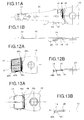
- Fig. 1A-1B show a structure of head assemblies including the piezoelectric actuators of the present invention.
- a plurality of carriage arms 30 are attached to a supporting shaft 28 and arranged in an axial direction of the shaft 28 with regular separations.
- the piezoelectric actuator 40 is fixed to a front end of the carriage arm 30 by caulking.
- a flexible printed circuit 50 is provided along side faces of the carriage arms 30.
- terminal sections of the head suspensions 20 and terminals of the piezoelectric actuators 40 are provided on the same side of the head assemblies. Namely, they are connected to the flexible printed circuit 50 on one side of the head assembly.
- Figs. 2A-3B Details of the piezoelectric actuator 40 is shown in Figs. 2A-3B.
- Fig. 2A is a plan view showing a state, in which the piezoelectric elements 12 are attached to an actuator base 10, which acts as a fixed member, with a first electrode member 16;
- Fig. 2B is a side view of the same state.
- Fig. 3A is a plan view showing a state, in which a hinge plate 14, which acts as a movable member, is further provided on the piezoelectric elements 12 shown in Figs. 2A and 2B;
- Fig. 3B is a side view of the same state.
- Figs. 2A is a plan view showing a state, in which a hinge plate 14, which acts as a movable member
- the piezoelectric actuator 40 of the present embodiment includes: the actuator base 10; the first electrode member 16; the piezoelectric elements 12; and the hinge plate 14. Unlike the conventional piezoelectric actuator, the piezoelectric actuator 40 has no second electrode member 18 (see Fig. 21). Namely, in the piezoelectric actuator 40, only the first electrode 16 is provided between the actuator base 10 and the piezoelectric elements 12.
- the carriage arm 30 is fixed on a bottom face of a base portion of the actuator base 10 by caulking.
- a positioning hole 11 is formed in the actuator base 10 so as to position the carriage arm 30 with respect to the actuator base 10 when the carriage arm 30 is caulked and fixed to the actuator base 10.
- a step section 10a is formed at a mid portion of the actuator base 10.
- level of a front portion of the actuator base 10, on which the piezoelectric elements 12 are mounted is lower than that of the base portion thereof, which is fixed to the carriage arm 30.
- level of the head suspension 20 and level of the base portion of the actuator base 10 can be almost equal when the head suspension 20 is attached to the piezoelectric actuator 40.
- thickness of the base portion of the actuator base 10, which is fixed to the carriage arm 30, is 0.2 mm; height of the step section 10a is 0.1-0.12 mm; thickness of the front portion of the actuator base 10, on which the piezoelectric elements 12 are mounted, is 0.1-0.15 mm.
- a clearance between the carriage arm 30 and a surface of a recording medium can be almost equal to that of the conventional disk drive unit. Since the thickness of the base portion of the actuator base 10, on which the piezoelectric elements 12 are mounted, is a half of the thickness of other portions of thereof, the level of the head suspension 20 can be almost equal to that of the base portion of the actuator base 10.
- the piezoelectric elements 12 are mounted on the actuator base 10 with the first electrode member 16.
- Electric potential of the carriage arm 30 is usually the earth potential, so the piezoelectric elements 12 must be electrically insulated from the actuator base 10, whose electric potential is also the earth potential.
- the first electrode member 16 comprises: a thin stainless steel layer, which contacts the actuator base 10; an insulating layer, which is formed on the thin stainless steel layer and made of an insulating material, e.g., polyimide; and a copper layer, which is formed on the insulating layer.
- the first electrode member 16 can be made very thinner by a known film forming technique. In the present embodiment, thickness of the first electrode member is 10-20 ⁇ m.
- the first electrode member 16 is broader than the piezoelectric elements 12. Namely, the first electrode member 16 is slightly extended outward from edges of the piezoelectric elements 12. Gold layers are formed on upper faces and lower faces of the piezoelectric elements 12 as electrodes. In the present embodiment, thickness of the gold electrodes are about 0.4 ⁇ m. Since the electrodes of the piezoelectric elements 12 are connected to cables by a proper manner, e.g., wire bonding, preferred thickness of the electrodes are 0.2 ⁇ m or more. By mounting the piezoelectric elements 12 on the first electrode member 16, the piezoelectric elements 12 can be electrically connected to the first electrode member 16. Note that, in Fig.
- arrows show polarizing directions of the piezoelectric elements 12 or directions of the shear stress in the piezoelectric elements 12. Since the piezoelectric elements 12, whose polarizing directions are mutually different, are mounted and fixed to the first electrode member 16, the head suspension 20 can be moved or turned, in a plane, in the right-left directions by the piezoelectric-deformation of the piezoelectric elements 12.
- the hinge plate 14 When the hinge plate 14 is attached to the piezoelectric elements 12 as shown in Fig. 3A, a part of the gold electrode of each piezoelectric element 12 is extended from a rear end of the hinge plate 14. With this arrangement, a part of the copper layer of the first electrode member 16 is also exposed. Since the gold electrodes of the piezoelectric elements 12 and the copper layer of the first electrode member 16 are partially exposed, the gold electrodes of the piezoelectric elements 12 can be electrically connected, by wire bonding, in the following step.
- the hinge plate 14 When the hinge plate 14 is attached on the upper faces of the piezoelectric elements 12, the hinge plate 14 must be electrically insulated from the piezoelectric elements 12. With this structure, cables for processing signals, which will be provided to the head suspension 20 and connected to the hinge plate 14, and cables for actuating the piezoelectric elements 12, which acts as the ground lines, are mutually insulated, so that no noises interface signals for reading and writing.
- the hinge plate 14 is insulated from and adhered on the piezoelectric elements 12.
- the hinge plate 14 is adhered on the piezoelectric elements 12 by an adhesive 34 which includes insulating fillers 32, whose diameters are about 15 ⁇ m. Fig.
- FIG. 4 shows the state, in which the hinge plate 14 is adhered on the piezoelectric element 12 by the adhesive 34 including the insulating fillers 32.
- the hinge plate 14 can be securely separated from the piezoelectric element 12 by the insulating fillers 32, so that the hinge plate 14 and the piezoelectric element 12 are electrically insulated and adhered each other. If the insulating fillers 32 are made of a soft material, damage and break of the piezoelectric elements 12, which are occurred when the hinge plate 14 is pressed onto the piezoelectric elements 12 so as to adhere, can be prevented.
- FIG. 5 projected sections 35, which are made of an insulating material, are previously formed in the surface of the piezoelectric elements 12, and the hinge plate 14 is adhered onto the piezoelectric elements 12 by an adhesive 34.
- the resin layers 35 may be formed by the steps of: masking a part of an aggregating body of the piezoelectric elements, in which a plurality of piezoelectric elements are arranged; coating an upper face of the aggregating body with the resin; and cutting the aggregating body to form the piezoelectric elements.
- the parts of the piezoelectric elements 12, on which the hinge plate 14 is adhered are coated with the resin layers 36, so that the hinge plate 14 can be securely insulated from and adhered on the piezoelectric elements 12. Even if the hinge plate 14 is pressed onto the piezoelectric elements 12, the hinge plate 14 can be adhered without damaging and breaking the piezoelectric elements 12. In comparison with the insulating fillers 32, thickness of the resin layers 36 can be precisely controlled, so assembling accuracy can be made higher. Note that, if the hinge plate 14 can be securely insulated from and adhered onto the piezoelectric elements 12, the insulating fillers 32 and the resin layers 36 can be omitted.
- Fig. 9 is a side view of the magnetic head assembly, in which the piezoelectric actuator 40 is attached to the head suspension 20;
- Fig. 10A is a plan view of another magnetic head assembly;
- Fig. 10B is a side view thereof.
- the head suspension is fixed to the hinge plate 14 by spot welding.
- a pair of cables 42 and 44 for actuating the piezoelectric elements 12 are formed on the head suspension 20.
- the cable 42 is connected to the piezoelectric elements 12 by wire bonding; the cable 44 is connected to the copper layer of the first electrode member 16 by wire bonding.
- Symbols 46 stand for bonding wires, which connect the cable 42 to the piezoelectric elements 12;
- a symbol 48 stands for a bonding wire, which connects the cable 44 to the first electrode member 16.
- the parts of the piezoelectric elements 12 are extended from the rear end of the hinge plate 14, and the gold electrode layers are exposed in the piezoelectric elements 12, so that the cable 42 and the gold electrodes can be easily connected by wire bonding.
- the cable 44 and the first electrode member 16 can be easily electrically connected by wire bonding to the copper layer of the first electrode member 16, which is extended from the piezoelectric elements 12. Since the copper layer of the first electrode member 16 is connected to the both piezoelectric elements 12, the cable 44 can be connected to the first electrode member 16 by one bonding wire 48.
- the bonding wires 46 and 48 are coated with resin, so that the bonding wires 46 and 48 are not damaged even if they are vibrated by air stream in the disk drive unit.
- Signal lines which are connected to a slider 22, are formed on the head suspension 20 and extended to a terminal section 24, which is formed by bending a side edge of the head suspension 20.
- the cables 42 and 44 for actuating the piezoelectric elements 12 are also extended to the terminal section 24 of the head suspension 20, so that their terminals and the terminals of the signal lines are located in the terminal section 24.
- the piezoelectric actuator 40 can be connected to an electric source via one flexible printed circuit, which is connected to the signal lines of the head suspension 20. Since the terminals of the cables 42 and 44 and the signal lines are provided in the terminal section 24, two flexible printed circuit, to which the cables and the signal lines are separately connected, are not required. Therefore, the one flexible printed circuit can be easily connected, assembling efficiency can be improved, and manufacturing cost can be reduced. Further, the terminals are provided in the same terminal section 24, the flexible printed circuit can be securely connected to the terminals.
- an extended section 20a is formed by partially extending a rear end of the head suspension 20 until reaching the actuator base 10.
- the extended section 20a is fixed to the actuator base 10 by spot welding.
- the head suspension 20 and the actuator base 10 are electrically connected, so that electric potential of the head suspension 20 can be the earth potential.
- the head suspension 20 can be deformed due to a slit formed in the extended section 20a.
- the slit is formed near the welding point, at which the head suspension 20 is fixed to the actuator base 10 by spot welding.
- FIGs. 10A and 10B Another magnetic head assembly is shown in Figs. 10A and 10B.
- the magnetic head assembly is characterized by no first electrode member 16.
- the actuator base 10 and the piezoelectric elements 12 are electrically insulated by the first electrode member 16.
- the piezoelectric elements 12 are directly mounted on the actuator base 10, so that electric potential of the one electrode of each piezoelectric element 12 is the earth potential.
- only the cable 42, which inputs voltage to the piezoelectric elements 12, may be provided to the head suspension 20.
- a pad section of the cable 42 which is formed at an end thereof, is electrically connected to the piezoelectric elements 12 by wire bonding. Another end of the cable 42 is extended to the terminal section 24 of the head suspension 20 as well as the former embodiment.
- the first electrode member 16 is omitted, so number of the parts can be further reduced. And, the piezoelectric actuator can be thinner.
- Figs. 11A-13B another embodiment is shown in Figs. 11A-13B.
- the cable patterns 42a and 44a for actuating the piezoelectric elements 12 are provided to the first electrode member 16, and the terminals 42b and 44b of the cable patterns 42 and 44 and the terminal section 24 of the head suspension 20 are formed on the same side.
- a terminal section 17 of the first electrode member 16 is formed by bending a side edge of the first electrode member 16, and the terminals 42b and 44b of the cable patterns 42a and 44a are located in the terminal section 17.
- the first electrode member 16 is adhered to the actuator base 10, and the piezoelectric elements 12 are fixed to the first electrode member 16.
- the first electrode member 16 has three layers: the thin stainless steel layer; the insulating layer; and the copper layer as well as the former embodiment.
- the cable pattern 44a is connected to the copper layer of the first electrode member 16; the cable pattern 42a is connected to the gold electrodes of the piezoelectric elements 12, which are formed on the upper faces thereof.
- a pad section 42c for wire bonding is formed at one end of the cable pattern 42a, which is extended outward from the piezoelectric elements 12: the terminal 42b is formed at the other end of the cable pattern 42a.
- the cable patterns 42a and 44a can be easily formed by a known film forming technique.
- the hinge plate 14 is fixed to the piezoelectric elements 12, and the piezoelectric elements 12 are connected to the cable pattern 42a by wire bonding.
- the hinge plate 14 is electrically insulated and adhered on the upper faces of the piezoelectric elements 12 as well as the former embodiment. Parts of the upper faces of the piezoelectric elements 12 are extended from a rear end of the hinge plate 14 and exposed.
- the piezoelectric elements 12 and the pad section 42c of the cable pattern 42a are electrically connected by wire bonding.
- the symbol 46 stands for the bonding wires.
- the adjacent piezoelectric elements 12 are connected by wire bonding, and the piezoelectric element 12 close to the pad section 42c is connected to the pad section 42c by wire bonding. With this structure, two piezoelectric elements 12 are electrically connected to the cable pattern 42a.
- the gold layers on the bottom faces of the piezoelectric elements 12 are connected to the copper layer of the first electrode member 16 and electrically connected to the terminal 44b by the cable pattern 44a; the gold layers on the upper faces of the piezoelectric elements 12 are electrically connected to the terminal 42b by the bonding wires 46 and the cable pattern 42a.
- the terminal section 24 and the terminals 42b and 44b for inputting voltage to the piezoelectric actuator 40 are formed on the same side, the electric source can be connected to the circuit for actuating the piezoelectric actuator 40 by the flexible printed circuit connected to the signal lines of the head suspension 20. Since the terminal sections 17 and 24 are corresponded, the flexible printed circuit can be easily connected to the terminal sections 17 and 24.
- the cable patterns 42a and 44a are formed in the first electrode member 16.
- the first electrode member 16 comprises: a thin stainless steel layer 161; an insulating layer 162, which is made of an insulating material, e.g., polyimide; and a copper layer 163.
- the cable patters 42a and 44a are formed by patterning the copper layer 163.
- a plurality of through-holes 161a are bored in the stainless steel layer 161, and fine projections 101 are formed in a part of the actuator base 10, on which the first electrode memberl6 is adhered, by proper means, e.g., laser, so as to improve adhering strength between the first electrode member 16 and the actuator base 10.
- the through-holes 161a and the fine projections 101 make contact area of an adhesive broader, so that the adhering strength can be made greater.
- the piezoelectric actuator 40 has the first electrode member 16 and the second electrode member 18.
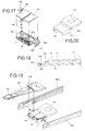
- Fig. 15 is an exploded perspective view of the piezoelectric actuator 40;
- Fig. 16 is a perspective view of the assembled piezoelectric actuator 40.
- the characteristic point of the present embodiment is a terminal 18b, which is formed in the second electrode member 18 and which is electrically connected to the pad section 42c of the first electrode member 16.
- the pad 42c is extended from the first electrode member 16; the terminal 18b is extended and corresponded to the pad section 42c.
- Fig. 17 shows the first electrode member 16 and the second electrode member 18.
- the pad section 42c of the first electrode member 16 and the terminal 18b of the second electrode member 18 are electrically connected when the piezoelectric elements 12 are sandwiched between the electrode members 16 and 18.
- the pad section 42c and the terminal 18b are electrically connected by a connecting member 49, e.g., electric conductive resin, a solder ball, a gold bump.
- Fig. 18 shows a state in which the first and second electrode members 16 and 18 and the piezoelectric elements 12 are piled.
- the terminal 18b is bent and connected to the pad section 42c by the connecting member 49.
- a slit 18c is formed in the terminal 18b.
- the extended terminal 18b can be easily bent. Since the second electrode member 18 is made of a thin metal plate, the upper electrodes of the piezoelectric elements 12 can be electrically connected to the terminal 42b by the cable pattern 42a when the terminal 18b is connected to the pad section 42c.
- the hinge plate 14 is electrically insulated from and adhered onto the second electrode member 18.
- the piezoelectric actuator 40 shown in Fig. 16 is completed by adhering the hinge plate 14.
- the terminals which are connected to the circuit for driving the piezoelectric actuator 40, and the terminal section 24 of the head suspension 20 are located on the same side.
- the terminal section for reading and writing data is provided to one side of the head suspension 20; the terminals connected to the circuit for driving the piezoelectric actuator 40 are provided to the other side of the head suspension 20.
- the characteristic point of the present embodiment is backup sections 52, which are formed into L-shape by bending both side edges of the actuator base 10. A perspective view of the actuator base 10 having the backup sections 52 is shown in Fig. 20.
- the first electrode member 16 is attached to the actuator base 10, and the terminal section 17 is held by an outer face of one of the backup sections 52. Since the head suspension 20 is attached to the hinge plate 14 by spot welding, the terminal section 24 of the head suspension 20 is held by an outer face of the other backup section 52. With this structure, the terminal section 18b of the first electrode member 16 can be securely held by the backup section 52, so a flexible printed circuit 50a can be securely connected to the terminals in the terminal section 18b. On the other hand, the terminal section 24 of the head suspension 20 can be securely held by the other backup section 52, so a flexible printed circuit 50b can be securely connected to the terminal section 24.
Landscapes
- Supporting Of Heads In Record-Carrier Devices (AREA)
- Moving Of The Head To Find And Align With The Track (AREA)
- General Electrical Machinery Utilizing Piezoelectricity, Electrostriction Or Magnetostriction (AREA)
- Adjustment Of The Magnetic Head Position Track Following On Tapes (AREA)
Applications Claiming Priority (2)
| Application Number | Priority Date | Filing Date | Title |
|---|---|---|---|
| JP2001243533 | 2001-08-10 | ||
| JP2001243533A JP2003061371A (ja) | 2001-08-10 | 2001-08-10 | 圧電アクチュエータ |
Publications (2)
| Publication Number | Publication Date |
|---|---|
| EP1288918A2 true EP1288918A2 (de) | 2003-03-05 |
| EP1288918A3 EP1288918A3 (de) | 2004-01-14 |
Family
ID=19073615
Family Applications (1)
| Application Number | Title | Priority Date | Filing Date |
|---|---|---|---|
| EP01310343A Withdrawn EP1288918A3 (de) | 2001-08-10 | 2001-12-11 | Piezoektrischer Betätiger |
Country Status (4)
| Country | Link |
|---|---|
| US (1) | US6741012B2 (de) |
| EP (1) | EP1288918A3 (de) |
| JP (1) | JP2003061371A (de) |
| KR (1) | KR100842461B1 (de) |
Families Citing this family (19)
| Publication number | Priority date | Publication date | Assignee | Title |
|---|---|---|---|---|
| JP2003123416A (ja) * | 2001-10-17 | 2003-04-25 | Fujitsu Ltd | ヘッドアセンブリおよび記録媒体駆動装置 |
| JP3756109B2 (ja) * | 2001-11-28 | 2006-03-15 | 富士通メディアデバイス株式会社 | 磁気ヘッド支持機構及び磁気ヘッド位置決め制御機構 |
| JP3866984B2 (ja) * | 2002-02-05 | 2007-01-10 | 富士通株式会社 | 磁気記憶装置 |
| JP4113143B2 (ja) * | 2004-03-15 | 2008-07-09 | Tdk株式会社 | 薄膜圧電体素子、サスペンション、及びハードディスク装置 |
| JP4585223B2 (ja) * | 2004-04-22 | 2010-11-24 | 東芝ストレージデバイス株式会社 | 圧電アクチュエータ及び圧電アクチュエータを用いたヘッドサスペンション装置 |
| JP4871593B2 (ja) * | 2006-01-06 | 2012-02-08 | キヤノン株式会社 | 振動子及び振動波駆動装置 |
| JP5189813B2 (ja) | 2007-09-27 | 2013-04-24 | 日本発條株式会社 | ヘッドサスペンション、及び圧電アクチュエータ |
| JP5318703B2 (ja) | 2008-09-08 | 2013-10-16 | 日本発條株式会社 | 圧電素子の電気的接続構造、圧電アクチュエータ、ヘッドサスペンション、及び導電性部材の電気的接続構造 |
| JP5100589B2 (ja) | 2008-09-19 | 2012-12-19 | 日本発條株式会社 | ヘッドサスペンション |
| JP5174649B2 (ja) * | 2008-12-25 | 2013-04-03 | 日本発條株式会社 | 圧電素子の電気的接続構造、圧電アクチュエータ及びヘッドサスペンション |
| JP5138571B2 (ja) | 2008-12-25 | 2013-02-06 | 日本発條株式会社 | 圧電素子の配線接続部構造、圧電アクチュエータ、及びヘッドサスペンション |
| JP4907675B2 (ja) | 2009-01-15 | 2012-04-04 | 日本発條株式会社 | 圧電素子の配線接続部構造、圧電アクチュエータ、及びヘッドサスペンション |
| JP4993625B2 (ja) | 2009-02-04 | 2012-08-08 | 日本発條株式会社 | 圧電素子の電極構造、圧電素子の電極形成方法、圧電アクチュエータ及びヘッドサスペンション |
| JP5285550B2 (ja) * | 2009-09-02 | 2013-09-11 | 日本発條株式会社 | 圧電アクチュエータの給電構造、及びヘッドサスペンション |
| JP5335658B2 (ja) | 2009-12-15 | 2013-11-06 | 日本発條株式会社 | ヘッドサスペンション、及びヘッドサスペンションの製造方法 |
| JP5875216B2 (ja) * | 2010-05-12 | 2016-03-02 | 日本発條株式会社 | 圧電素子の電気的接続構造の製造方法 |
| JP5943590B2 (ja) * | 2011-01-07 | 2016-07-05 | 日本発條株式会社 | 圧電素子の製造方法、圧電素子、圧電アクチュエータ、及びヘッド・サスペンション |
| US8456780B1 (en) | 2012-02-10 | 2013-06-04 | HGST Netherlands B.V. | Uncoupled piezoelectric milli-actuator assembly |
| KR102247501B1 (ko) * | 2014-05-09 | 2021-05-03 | 삼성전자주식회사 | 압전 구동 장치 및 이를 이용한 움직임 측정 방법 |
Citations (2)
| Publication number | Priority date | Publication date | Assignee | Title |
|---|---|---|---|---|
| DE19816909A1 (de) | 1997-04-17 | 1998-11-12 | Fujitsu Ltd | Betätigungsglied mit Piezoelement sowie dieses Betätigungselement einsetzender Kopfpositionierungsmechanismus |
| JP2001043641A (ja) | 1999-07-30 | 2001-02-16 | Fujitsu Ltd | ヘッドの微小移動機構 |
Family Cites Families (4)
| Publication number | Priority date | Publication date | Assignee | Title |
|---|---|---|---|---|
| IL114656A0 (en) * | 1995-07-18 | 1995-11-27 | Nanomotion Ltd | Ceramic motor |
| US6362542B1 (en) * | 1997-08-15 | 2002-03-26 | Seagate Technology Llc | Piezoelectric microactuator for precise head positioning |
| US6233124B1 (en) * | 1998-11-18 | 2001-05-15 | Seagate Technology Llc | Piezoelectric microactuator suspension assembly with improved stroke length |
| US6307301B1 (en) * | 2000-02-02 | 2001-10-23 | The Boeing Company | Buckling resistant piezoelectric actuator |
-
2001
- 2001-08-10 JP JP2001243533A patent/JP2003061371A/ja active Pending
- 2001-12-11 EP EP01310343A patent/EP1288918A3/de not_active Withdrawn
- 2001-12-19 US US10/025,018 patent/US6741012B2/en not_active Expired - Fee Related
- 2001-12-19 KR KR1020010081057A patent/KR100842461B1/ko not_active Expired - Fee Related
Patent Citations (2)
| Publication number | Priority date | Publication date | Assignee | Title |
|---|---|---|---|---|
| DE19816909A1 (de) | 1997-04-17 | 1998-11-12 | Fujitsu Ltd | Betätigungsglied mit Piezoelement sowie dieses Betätigungselement einsetzender Kopfpositionierungsmechanismus |
| JP2001043641A (ja) | 1999-07-30 | 2001-02-16 | Fujitsu Ltd | ヘッドの微小移動機構 |
Also Published As
| Publication number | Publication date |
|---|---|
| US20020043894A1 (en) | 2002-04-18 |
| KR20030014093A (ko) | 2003-02-15 |
| JP2003061371A (ja) | 2003-02-28 |
| KR100842461B1 (ko) | 2008-07-01 |
| EP1288918A3 (de) | 2004-01-14 |
| US6741012B2 (en) | 2004-05-25 |
Similar Documents
| Publication | Publication Date | Title |
|---|---|---|
| US6741012B2 (en) | Piezoelectric actuator | |
| US7099115B2 (en) | Head gimbal assembly with precise positioning actuator for head element, disk drive apparatus with the head gimbal assembly, and manufacturing method of the head gimbal assembly | |
| US8570688B1 (en) | Electrical connections to a microactuator in a hard disk drive suspension | |
| US8934203B2 (en) | Disk drive suspension | |
| JP2934126B2 (ja) | 磁気ディスク装置用の磁気ヘッドユニット | |
| US6671131B2 (en) | Precise positioning actuator for head element, head gimbal assembly with the actuator and manufacturing method of head gimbal assembly | |
| CN101399505B (zh) | 头悬架和压电执行机构 | |
| US8970990B2 (en) | Disk drive suspension | |
| US8405934B2 (en) | Electronic apparatus and disk drive suspension | |
| US5802701A (en) | Method of making an integrated suspension, actuator arm and coil assembly | |
| KR100371999B1 (ko) | 바이몰프 압전성 마이크로액츄에이터 헤드 및 플렉서 어셈블리 | |
| WO2004084219A1 (en) | System and method for manufacturing a hard disk drive suspension flexure and for preventing damage due to electrical arcing | |
| CN113362861A (zh) | 悬架组件以及盘装置 | |
| JP7413237B2 (ja) | サスペンションアッセンブリおよびディスク装置 | |
| JP2020135906A (ja) | ヘッドサスペンションアッセンブリおよびディスク装置 | |
| CN109637556B (zh) | 磁盘驱动器悬架的电路构件 | |
| CN113393867B (zh) | 悬架组件以及盘装置 | |
| CN111653295A (zh) | 微驱动器、头悬挂组件以及盘装置 | |
| JP2024043086A (ja) | サスペンションアッセンブリおよびディスク装置 | |
| CN108962287A (zh) | 磁盘驱动器悬架的电路部件 | |
| US7542242B2 (en) | FPC with via holes with filler being welded to suspension and drive apparatus | |
| JP4585223B2 (ja) | 圧電アクチュエータ及び圧電アクチュエータを用いたヘッドサスペンション装置 | |
| JP7731825B2 (ja) | ディスク装置用サスペンション | |
| JP2023097516A (ja) | ヘッドサスペンションアッセンブリおよびディスク装置 | |
| HK1044621A1 (zh) | 磁頭萬向架組件 |
Legal Events
| Date | Code | Title | Description |
|---|---|---|---|
| PUAI | Public reference made under article 153(3) epc to a published international application that has entered the european phase |
Free format text: ORIGINAL CODE: 0009012 |
|
| AK | Designated contracting states |
Kind code of ref document: A2 Designated state(s): AT BE CH CY DE DK ES FI FR GB GR IE IT LI LU MC NL PT SE TR Designated state(s): AT BE CH CY DE DK ES FI FR GB GR IE IT LI LU MC NL PT SE TR |
|
| AX | Request for extension of the european patent |
Extension state: AL LT LV MK RO SI |
|
| PUAL | Search report despatched |
Free format text: ORIGINAL CODE: 0009013 |
|
| AK | Designated contracting states |
Kind code of ref document: A3 Designated state(s): AT BE CH CY DE DK ES FI FR GB GR IE IT LI LU MC NL PT SE TR |
|
| AX | Request for extension of the european patent |
Extension state: AL LT LV MK RO SI |
|
| 17P | Request for examination filed |
Effective date: 20040504 |
|
| AKX | Designation fees paid |
Designated state(s): DE FR GB |
|
| 17Q | First examination report despatched |
Effective date: 20080115 |
|
| RAP1 | Party data changed (applicant data changed or rights of an application transferred) |
Owner name: TOSHIBA STORAGE DEVICE CORPORATION |
|
| STAA | Information on the status of an ep patent application or granted ep patent |
Free format text: STATUS: THE APPLICATION IS DEEMED TO BE WITHDRAWN |
|
| 18D | Application deemed to be withdrawn |
Effective date: 20110701 |