EP1288459A2 - Abgaskrümmer einer Abgasanlage für eine Brennkraftmaschine - Google Patents
Abgaskrümmer einer Abgasanlage für eine Brennkraftmaschine Download PDFInfo
- Publication number
- EP1288459A2 EP1288459A2 EP02015741A EP02015741A EP1288459A2 EP 1288459 A2 EP1288459 A2 EP 1288459A2 EP 02015741 A EP02015741 A EP 02015741A EP 02015741 A EP02015741 A EP 02015741A EP 1288459 A2 EP1288459 A2 EP 1288459A2
- Authority
- EP
- European Patent Office
- Prior art keywords
- exhaust pipes
- exhaust
- edge
- pipes
- pipe
- Prior art date
- Legal status (The legal status is an assumption and is not a legal conclusion. Google has not performed a legal analysis and makes no representation as to the accuracy of the status listed.)
- Granted
Links
Images

Classifications
-
- F—MECHANICAL ENGINEERING; LIGHTING; HEATING; WEAPONS; BLASTING
- F01—MACHINES OR ENGINES IN GENERAL; ENGINE PLANTS IN GENERAL; STEAM ENGINES
- F01N—GAS-FLOW SILENCERS OR EXHAUST APPARATUS FOR MACHINES OR ENGINES IN GENERAL; GAS-FLOW SILENCERS OR EXHAUST APPARATUS FOR INTERNAL-COMBUSTION ENGINES
- F01N13/00—Exhaust or silencing apparatus characterised by constructional features
- F01N13/08—Other arrangements or adaptations of exhaust conduits
- F01N13/10—Other arrangements or adaptations of exhaust conduits of exhaust manifolds
- F01N13/102—Other arrangements or adaptations of exhaust conduits of exhaust manifolds having thermal insulation
-
- F—MECHANICAL ENGINEERING; LIGHTING; HEATING; WEAPONS; BLASTING
- F01—MACHINES OR ENGINES IN GENERAL; ENGINE PLANTS IN GENERAL; STEAM ENGINES
- F01N—GAS-FLOW SILENCERS OR EXHAUST APPARATUS FOR MACHINES OR ENGINES IN GENERAL; GAS-FLOW SILENCERS OR EXHAUST APPARATUS FOR INTERNAL-COMBUSTION ENGINES
- F01N13/00—Exhaust or silencing apparatus characterised by constructional features
-
- F—MECHANICAL ENGINEERING; LIGHTING; HEATING; WEAPONS; BLASTING
- F01—MACHINES OR ENGINES IN GENERAL; ENGINE PLANTS IN GENERAL; STEAM ENGINES
- F01N—GAS-FLOW SILENCERS OR EXHAUST APPARATUS FOR MACHINES OR ENGINES IN GENERAL; GAS-FLOW SILENCERS OR EXHAUST APPARATUS FOR INTERNAL-COMBUSTION ENGINES
- F01N2260/00—Exhaust treating devices having provisions not otherwise provided for
- F01N2260/10—Exhaust treating devices having provisions not otherwise provided for for avoiding stress caused by expansions or contractions due to temperature variations
-
- Y—GENERAL TAGGING OF NEW TECHNOLOGICAL DEVELOPMENTS; GENERAL TAGGING OF CROSS-SECTIONAL TECHNOLOGIES SPANNING OVER SEVERAL SECTIONS OF THE IPC; TECHNICAL SUBJECTS COVERED BY FORMER USPC CROSS-REFERENCE ART COLLECTIONS [XRACs] AND DIGESTS
- Y10—TECHNICAL SUBJECTS COVERED BY FORMER USPC
- Y10T—TECHNICAL SUBJECTS COVERED BY FORMER US CLASSIFICATION
- Y10T29/00—Metal working
- Y10T29/49—Method of mechanical manufacture
- Y10T29/49398—Muffler, manifold or exhaust pipe making
Definitions
- the invention relates to an exhaust manifold of an exhaust system for a Internal combustion engine according to the preamble of patent claim 1.
- An exhaust manifold with exhaust pipes is known from EP 0 806 598 A1 merged area are interconnected and otherwise angled diverge and do not lie side by side in the same direction. Furthermore, is out US 6,122,911 an exhaust manifold is known in which the merged Exhaust pipes are merged into a segment of a circle and each pipe Form quarter circle segments and the walls of these quarter circle segments only on the corner side lie next to each other and otherwise have a gap.
- the object of the invention is to provide an improved exhaust manifold for an exhaust system to create an internal combustion engine in which noises, in particular rattling noises be avoided.
- the main advantages achieved with the invention are that by Separation of the exhaust pipes as far as possible, especially when they are close lying next to each other and arranged in the same direction, a noise reduction is achievable.
- the exhaust pipes are arranged in the pipe bend in the same direction and form a circular cross section at the ends, the exhaust pipes at the free end on the one hand via a defined peripheral contact surface with each other are connected and on the other hand the rectified exhaust pipes in the further course stand apart from each other with a gap.
- the invention provides in particular that the free ends of the exhaust pipes each opening into the elbow are triangular as quarter-circle segments and each pipe end a relative has a narrow edge, which is compared to the remaining area of the exhaust pipes is projecting outside and there is a gap between the exhaust pipes. This will achieved that the exhaust pipes only at the pipe edge over a relatively narrow area - defined even at different temperatures - lying next to each other and otherwise the pipes are slightly separated from each other via the gap.
- the contiguous Pipe edges are either flat or have beads that interlock to grab.
- the exhaust pipes are exposed or only across a gap arranged and in such a way that the motor side on the mounting flange held exhaust pipes in the exhaust manifold housing with the continuing exhaust pipes are each connected via a sliding seat and that the exhaust pipes from The mounting flange is exposed over the edge until it is received in the elbow are arranged.
- the sliding seat between the exhaust pipes in the housing of the Exhaust manifold causes thermal expansion on the one hand and other possible degradation due to friction between the pipes Vibrations of the exhaust pipes.
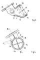
- An exhaust manifold 1 of an exhaust system for an internal combustion engine comprises essentially an exhaust manifold housing 2 with an engine-side mounting flange 3 and arranged in the housing 2 exhaust pipes 4 to 7 for one half Eight-cylinder engine. On the housing 2, a pipe bend 8 is connected, the further exhaust pipes 4a to 7a is connected.
- the exhaust pipes 4 to 7 and 4a to 7a run from the mounting flange 3 on the engine to to the inlet opening 10 in the elbow 8, in which it means with its free ends of a raised flat edge 11 are held in an inner tube 12.
- the edge 11 of narrow width a and is above the remaining pipe cross section of the exhaust pipes 4a to 7a so that the subsequent rectified areas of the exhaust pipes to each other have a gap 21 and are arranged at a gap distance b from one another.
- the free ends of the exhaust pipes 4a to 7a are closed at the ends Quarter circle segments 20 formed and together form a cross section Circular opening. These quarter circle segments 20 each have the edge 11.
- Inner tube 12 is arranged, the flange 22 with the outer tube 13th is merged. Between the outer tube 13 and the inner tube 12 is in the area of the edge 11, a spacer ring or a so-called knitted wire ring 14 is provided.
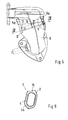
- the engine-side exhaust pipes 4 to 7 are connected to the flange 3, as shown in FIG. 2 shows and are via a sliding seat connection 15 with the subsequent, connected further exhaust pipes 4a to 7a. With this connection, the Exhaust pipes 4a to 7a plugged into the corresponding exhaust pipes 4 to 7, as shown in FIG. 6 shows closer.
- the exhaust pipes 4 to 7 and 4a to 7a are in the mounting flange 3 to Connection in the elbow 8 spaced over the edge 11 in the inner tube 12 arranged to each other or they are in the housing 2 to the wall at a distance laid.
Landscapes
- Engineering & Computer Science (AREA)
- Chemical & Material Sciences (AREA)
- Combustion & Propulsion (AREA)
- Mechanical Engineering (AREA)
- General Engineering & Computer Science (AREA)
- Exhaust Silencers (AREA)
- Control Of Throttle Valves Provided In The Intake System Or In The Exhaust System (AREA)
Abstract
Description
- Fig. 1
- eine Ansicht auf einen Abgaskrümmer mit Befestigungsflansch und Rohrkrümmer,
- Fig. 2
- eine Draufsicht auf den Abgaskrümmer gem. Fig. 1 mit innenliegenden Abgasrohren,
- Fig. 3
- einen Schnitt durch den Rohrkrümmer nach der Linie III-III der Fig. 4,
- Fig. 4
- einen Schnitt durch den Rohrkrümmer mit verbundenen Abgasrohren gem. der Linie IV-IV der Fig. 5,
- Fig. 5
- eine Ansicht auf den Rohrkrümmer in Pfeilrichtung Z der Fig. 1 gesehen und
- Fig. 6
- einen Schnitt nach der Linie VI-VI der Fig. 2 durch einen Schiebesitz der Abgasrohre.
Claims (5)
- Abgaskrümmer einer Abgasanlage für eine Brennkraftmaschine mit einem abzweigenden Rohrkrümmer, in den motorseitig verbundene Abgasrohre einmünden und in einem Abschnitt des Rohrkrümmers zusammengefaßt und in diesem endseitig gehalten sind, dadurch gekennzeichnet, daß die Abgasrohre (4a bis 7a) im Rohrkrümmer (8) gleichgerichtet angeordnet sind und endseitig miteinander einen Kreisquerschnitt ergeben, wobei die Abgasrohre (4a bis 7a) am freien Ende einerseits über eine definierte randseitige umlaufende Anlagefläche (Rand 11) mit der Breite (a) miteinander verbunden sind und andererseits die gleichgerichteten Abgasrohre (4a bis 7a) im weiteren Verlauf mit einem Spalt (21) beabstandet zueinander stehen.
- Abgaskrümmer nach Anspruch 1, dadurch gekennzeichnet, daß die in den Rohrkrümmer (8) einmündenden freien Enden der Abgasrohre (4a bis 7a) jeweils dreieckförmig als Viertelkreissegmente (20) ausgebildet sind und jedes Rohrende den Rand (11) aufweist, der gegenüber dem übrigen Bereich des Abgasrohres (4a bis 7a) nach außen vorstehend ist und sich zwischen den Abgasrohren (4a bis 7a) der Spalt (21) ergibt.
- Abgaskrümmer nach den Ansprüchen 1 oder 2, dadurch gekennzeichnet, daß der Rand (11) eine Breite (a) von etwa 5 mm aufweist und der Spalt (21) zwischen den Abgasrohren (4a bis 7a) etwa ein Maß von b = 2 mm besitzt.
- Abgaskrümmer nach den Ansprüchen 1, 2 oder 3, dadurch gekennzeichnet, daß zu einem Außenrohr (13) des Rohrkrümmers (8) beabstandet ein innerer Rohrbogen (12) angeordnet ist, in welchem die freien Enden der Abgasrohre (4a bis 7a) mit dem Rand (11) eingesteckt angeordnet sind und zwischen dem Außenrohr (13) und dem Rohrbogen (12) im Bereich der Ränder (11) ein Drahtgestrickring (14) vorgesehen ist.
- Abgaskrümmer nach den Ansprüchen 1, 2, 3 oder 4, dadurch gekennzeichnet, daß die motorseitig über einen Befestigungsflansch (3) gehaltenen weiteren Abgasrohre (4 bis 7) im Abgaskrümmergehäuse (2) mit den weiterführenden Abgasrohren (4a bis 7a) jeweils über einen Schiebesitz (15) verbunden sind und daß die Abgasrohre (4 bis 7) und (4a bis 7a) vom Befestigungsflansch (3) bis zur Aufnahme im Rohrkrümmer (8) über den Rand (11) freiliegend angeordnet sind.
Applications Claiming Priority (2)
| Application Number | Priority Date | Filing Date | Title |
|---|---|---|---|
| DE10142979 | 2001-09-01 | ||
| DE10142979A DE10142979C1 (de) | 2001-09-01 | 2001-09-01 | Abgaskrümmer einer Abgasanlage für eine Brennkraftmaschine |
Publications (3)
| Publication Number | Publication Date |
|---|---|
| EP1288459A2 true EP1288459A2 (de) | 2003-03-05 |
| EP1288459A3 EP1288459A3 (de) | 2004-06-09 |
| EP1288459B1 EP1288459B1 (de) | 2006-03-22 |
Family
ID=7697450
Family Applications (1)
| Application Number | Title | Priority Date | Filing Date |
|---|---|---|---|
| EP02015741A Expired - Lifetime EP1288459B1 (de) | 2001-09-01 | 2002-07-13 | Abgaskrümmer einer Abgasanlage für eine Brennkraftmaschine |
Country Status (6)
| Country | Link |
|---|---|
| US (1) | US6959543B2 (de) |
| EP (1) | EP1288459B1 (de) |
| JP (1) | JP2003129839A (de) |
| AT (1) | ATE321197T1 (de) |
| DE (2) | DE10142979C1 (de) |
| ES (1) | ES2257491T3 (de) |
Families Citing this family (8)
| Publication number | Priority date | Publication date | Assignee | Title |
|---|---|---|---|---|
| JP3973987B2 (ja) * | 2002-07-19 | 2007-09-12 | 川崎重工業株式会社 | 多気筒エンジンの集合型排気管および小型滑走艇 |
| DE20303759U1 (de) * | 2003-03-10 | 2004-07-22 | Friedrich Boysen Gmbh & Co. Kg | Abgasanlage einer Brennkraftmaschine |
| KR100610852B1 (ko) * | 2004-07-06 | 2006-08-08 | 현대자동차주식회사 | 자동차의 배기 매니폴드 |
| FR2886338A1 (fr) * | 2005-05-24 | 2006-12-01 | Renault Sas | Collecteur d'echappement a double paroi pour moteur a combustion interne |
| US8382807B2 (en) | 2005-07-25 | 2013-02-26 | Smith & Nephew, Inc. | Systems and methods for using polyaxial plates |
| JP4622962B2 (ja) * | 2005-11-30 | 2011-02-02 | 株式会社デンソー | インタークーラの出入口配管構造 |
| JP4834041B2 (ja) * | 2008-08-04 | 2011-12-07 | 本田技研工業株式会社 | 排ガス浄化装置 |
| EP2524199B1 (de) * | 2010-01-15 | 2018-05-02 | Skyventure International (UK) Ltd. | Wärmetauscher in windkanal-leitschaufel |
Citations (2)
| Publication number | Priority date | Publication date | Assignee | Title |
|---|---|---|---|---|
| EP0806598A1 (de) | 1996-05-08 | 1997-11-12 | Sango Co., Ltd. | Abzweigrohr und Verfahren zu dessen Herstellung |
| US6122911A (en) | 1998-09-28 | 2000-09-26 | Honda Giken Kogyo Kabushiki Kaisha | Exhaust manifold pipe weld assembly |
Family Cites Families (22)
| Publication number | Priority date | Publication date | Assignee | Title |
|---|---|---|---|---|
| US2847819A (en) * | 1952-11-07 | 1958-08-19 | Gen Motors Corp | Reversible exhaust manifold system |
| FR2203426A5 (de) * | 1972-10-17 | 1974-05-10 | Luchaire Sa | |
| DE2251777A1 (de) * | 1972-10-21 | 1974-05-02 | Porsche Kg | Mehrteilige gasleitung |
| US4188784A (en) * | 1976-10-26 | 1980-02-19 | Chrysler Corporation | Articulated exhaust system |
| JPS57143119A (en) * | 1981-02-26 | 1982-09-04 | Nippon Radiator Co Ltd | Exhaust device |
| JPH0615817B2 (ja) * | 1985-05-14 | 1994-03-02 | 本田技研工業株式会社 | 多気筒内燃エンジンの排気マニホ−ルド |
| FR2612252B1 (fr) * | 1987-03-09 | 1992-04-03 | Peugeot | Dispositif de raccordement de conduits d'echappement et moteur a combustion interne equipe de ce dispositif |
| JP2562616B2 (ja) | 1987-09-14 | 1996-12-11 | ヤマハ発動機株式会社 | 自動二輪車の排気制御装置 |
| JPH01138311A (ja) * | 1987-11-24 | 1989-05-31 | Mazda Motor Corp | エンジンの排気通路構造 |
| DE3740791A1 (de) * | 1987-12-02 | 1989-06-22 | Bayerische Motoren Werke Ag | Rohrleitungssystem |
| EP0662564B2 (de) * | 1994-01-07 | 2001-09-26 | J. Eberspächer GmbH & Co. | Luftspaltisoliertes Abgasrohr und Verfahren zu seiner Herstellung |
| JPH0828257A (ja) * | 1994-07-11 | 1996-01-30 | Toyota Motor Corp | 二重排気管 |
| JP3334454B2 (ja) * | 1995-04-03 | 2002-10-15 | トヨタ自動車株式会社 | エキゾーストマニホルド集合部構造 |
| DE19526084A1 (de) * | 1995-07-18 | 1997-01-23 | Porsche Ag | Abgasrohrkrümmer |
| JP3279162B2 (ja) * | 1995-12-26 | 2002-04-30 | トヨタ自動車株式会社 | エキゾーストマニホルドの排気集合部構造 |
| JPH09264129A (ja) * | 1996-01-25 | 1997-10-07 | Aisin Takaoka Ltd | 排気マニホルド |
| JPH09280042A (ja) * | 1996-04-09 | 1997-10-28 | Toyota Motor Corp | 内燃機関の排気マニホルド |
| DE19917604C5 (de) * | 1998-04-20 | 2009-09-10 | Honda Giken Kogyo K.K. | Wärmeisolierter Abgaskrümmer |
| US6199376B1 (en) * | 1998-09-28 | 2001-03-13 | Honda Giken Kogyo Kabushiki Kaisha | Extension of exhaust manifold conduit into exhaust pipe |
| JP3426549B2 (ja) * | 1999-11-12 | 2003-07-14 | 本田技研工業株式会社 | 排気管の接続構造 |
| JP4262381B2 (ja) * | 1999-12-28 | 2009-05-13 | 株式会社ユタカ技研 | エンジン用二重排気管及びエンジン用排気マニホールド |
| JP2002155720A (ja) * | 2000-11-20 | 2002-05-31 | Yamaha Motor Co Ltd | ブローバイガス還元装置のユニオン構造 |
-
2001
- 2001-09-01 DE DE10142979A patent/DE10142979C1/de not_active Expired - Fee Related
-
2002
- 2002-07-13 EP EP02015741A patent/EP1288459B1/de not_active Expired - Lifetime
- 2002-07-13 ES ES02015741T patent/ES2257491T3/es not_active Expired - Lifetime
- 2002-07-13 AT AT02015741T patent/ATE321197T1/de not_active IP Right Cessation
- 2002-07-13 DE DE50206114T patent/DE50206114D1/de not_active Expired - Lifetime
- 2002-08-27 JP JP2002246700A patent/JP2003129839A/ja active Pending
- 2002-08-30 US US10/231,465 patent/US6959543B2/en not_active Expired - Fee Related
Patent Citations (2)
| Publication number | Priority date | Publication date | Assignee | Title |
|---|---|---|---|---|
| EP0806598A1 (de) | 1996-05-08 | 1997-11-12 | Sango Co., Ltd. | Abzweigrohr und Verfahren zu dessen Herstellung |
| US6122911A (en) | 1998-09-28 | 2000-09-26 | Honda Giken Kogyo Kabushiki Kaisha | Exhaust manifold pipe weld assembly |
Also Published As
| Publication number | Publication date |
|---|---|
| US20030056505A1 (en) | 2003-03-27 |
| DE10142979C1 (de) | 2003-05-28 |
| ATE321197T1 (de) | 2006-04-15 |
| ES2257491T3 (es) | 2006-08-01 |
| EP1288459A3 (de) | 2004-06-09 |
| JP2003129839A (ja) | 2003-05-08 |
| DE50206114D1 (de) | 2006-05-11 |
| US6959543B2 (en) | 2005-11-01 |
| EP1288459B1 (de) | 2006-03-22 |
Similar Documents
| Publication | Publication Date | Title |
|---|---|---|
| DE112006003631B4 (de) | Wartungsfähige ausgerichtete Abgasnachbehandlungsanordnung | |
| EP1245886B1 (de) | Mehrlagiger Schlauch aus profiliertem Bandmaterial | |
| DE102008027662A1 (de) | Ölwanne mit Ölfilter | |
| WO1999000600A1 (de) | Kältemittelkompressor | |
| DE10142979C1 (de) | Abgaskrümmer einer Abgasanlage für eine Brennkraftmaschine | |
| DE9419537U1 (de) | Abgasklappen-Anordnung | |
| DE102004019619B3 (de) | Reinigungsrotor | |
| EP1422413B1 (de) | Ansaugsystem | |
| EP1611339B1 (de) | Kraftstofffilter für ein kraftfahrzeug | |
| DE102014017026A1 (de) | Filtereinsatz für eine Filtereinrichtung | |
| DE29518501U1 (de) | Vorrichtung zum Verbinden des Ansaugstutzens einer Kraftstoffpumpe mit einem aus Kunststoff bestehenden Kraftstoffilter | |
| DE102010048865A1 (de) | Abgasrückführventil | |
| DE3514475A1 (de) | Schalldaempfer fuer die abgase einer brennkraftmaschine | |
| DE102022103039A1 (de) | Regelvorrichtung eines Abgasführungsabschnitts eines Abgasturboladers | |
| DE4434560C2 (de) | Kraftstoff-Einspritzanlage | |
| WO2016184617A1 (de) | Abgasturbolader | |
| DE1476625A1 (de) | Auspuffgeraeuschdaempfer,insbesondere fuer Viertakt-Verbrennungsmotoren | |
| DE10024614B4 (de) | Abgaskrümmer eines Motors | |
| EP1691050B1 (de) | Schalldämpfer | |
| DE1767532C3 (de) | Abgasein- oder Austrittsboden für Katalysatormaterial zur Reinigung der Abgase von Brennkraftmaschinen | |
| DE102007059786A1 (de) | Dunstabzugsvorrichtung | |
| EP3401584A1 (de) | Rohr, insbesondere abgasführungsrohr | |
| DE10339308B4 (de) | Abdeckgehäuse für eine Brennkraftmaschine | |
| DE102017216226A1 (de) | Antriebseinrichtung für ein Kraftfahrzeug sowie entsprechendes Kraftfahrzeug | |
| DE8315430U1 (de) | Schalldaempfer fuer kompressoren u. dgl. |
Legal Events
| Date | Code | Title | Description |
|---|---|---|---|
| PUAI | Public reference made under article 153(3) epc to a published international application that has entered the european phase |
Free format text: ORIGINAL CODE: 0009012 |
|
| AK | Designated contracting states |
Kind code of ref document: A2 Designated state(s): AT BE BG CH CY CZ DE DK EE ES FI FR GB GR IE IT LI LU MC NL PT SE SK TR |
|
| AX | Request for extension of the european patent |
Extension state: AL LT LV MK RO SI |
|
| PUAL | Search report despatched |
Free format text: ORIGINAL CODE: 0009013 |
|
| AK | Designated contracting states |
Kind code of ref document: A3 Designated state(s): AT BE BG CH CY CZ DE DK EE ES FI FR GB GR IE IT LI LU MC NL PT SE SK TR |
|
| AX | Request for extension of the european patent |
Extension state: AL LT LV MK RO SI |
|
| 17P | Request for examination filed |
Effective date: 20041209 |
|
| 17Q | First examination report despatched |
Effective date: 20050118 |
|
| AKX | Designation fees paid |
Designated state(s): AT BE BG CH CY CZ DE DK EE ES FI FR GB GR IE IT LI LU MC NL PT SE SK TR |
|
| GRAP | Despatch of communication of intention to grant a patent |
Free format text: ORIGINAL CODE: EPIDOSNIGR1 |
|
| GRAS | Grant fee paid |
Free format text: ORIGINAL CODE: EPIDOSNIGR3 |
|
| GRAA | (expected) grant |
Free format text: ORIGINAL CODE: 0009210 |
|
| AK | Designated contracting states |
Kind code of ref document: B1 Designated state(s): AT BE BG CH CY CZ DE DK EE ES FI FR GB GR IE IT LI LU MC NL PT SE SK TR |
|
| PG25 | Lapsed in a contracting state [announced via postgrant information from national office to epo] |
Ref country code: SK Free format text: LAPSE BECAUSE OF FAILURE TO SUBMIT A TRANSLATION OF THE DESCRIPTION OR TO PAY THE FEE WITHIN THE PRESCRIBED TIME-LIMIT Effective date: 20060322 Ref country code: IE Free format text: LAPSE BECAUSE OF FAILURE TO SUBMIT A TRANSLATION OF THE DESCRIPTION OR TO PAY THE FEE WITHIN THE PRESCRIBED TIME-LIMIT Effective date: 20060322 Ref country code: NL Free format text: LAPSE BECAUSE OF FAILURE TO SUBMIT A TRANSLATION OF THE DESCRIPTION OR TO PAY THE FEE WITHIN THE PRESCRIBED TIME-LIMIT Effective date: 20060322 |
|
| REG | Reference to a national code |
Ref country code: GB Ref legal event code: FG4D Free format text: NOT ENGLISH |
|
| REG | Reference to a national code |
Ref country code: CH Ref legal event code: EP |
|
| REG | Reference to a national code |
Ref country code: IE Ref legal event code: FG4D Free format text: LANGUAGE OF EP DOCUMENT: GERMAN |
|
| REG | Reference to a national code |
Ref country code: SE Ref legal event code: TRGR |
|
| REF | Corresponds to: |
Ref document number: 50206114 Country of ref document: DE Date of ref document: 20060511 Kind code of ref document: P |
|
| GBT | Gb: translation of ep patent filed (gb section 77(6)(a)/1977) |
Effective date: 20060518 |
|
| PG25 | Lapsed in a contracting state [announced via postgrant information from national office to epo] |
Ref country code: DK Free format text: LAPSE BECAUSE OF FAILURE TO SUBMIT A TRANSLATION OF THE DESCRIPTION OR TO PAY THE FEE WITHIN THE PRESCRIBED TIME-LIMIT Effective date: 20060622 Ref country code: BG Free format text: LAPSE BECAUSE OF FAILURE TO SUBMIT A TRANSLATION OF THE DESCRIPTION OR TO PAY THE FEE WITHIN THE PRESCRIBED TIME-LIMIT Effective date: 20060622 |
|
| PG25 | Lapsed in a contracting state [announced via postgrant information from national office to epo] |
Ref country code: LI Free format text: LAPSE BECAUSE OF NON-PAYMENT OF DUE FEES Effective date: 20060731 Ref country code: MC Free format text: LAPSE BECAUSE OF NON-PAYMENT OF DUE FEES Effective date: 20060731 Ref country code: CH Free format text: LAPSE BECAUSE OF NON-PAYMENT OF DUE FEES Effective date: 20060731 Ref country code: BE Free format text: LAPSE BECAUSE OF NON-PAYMENT OF DUE FEES Effective date: 20060731 |
|
| REG | Reference to a national code |
Ref country code: ES Ref legal event code: FG2A Ref document number: 2257491 Country of ref document: ES Kind code of ref document: T3 |
|
| PG25 | Lapsed in a contracting state [announced via postgrant information from national office to epo] |
Ref country code: PT Free format text: LAPSE BECAUSE OF FAILURE TO SUBMIT A TRANSLATION OF THE DESCRIPTION OR TO PAY THE FEE WITHIN THE PRESCRIBED TIME-LIMIT Effective date: 20060822 |
|
| NLV1 | Nl: lapsed or annulled due to failure to fulfill the requirements of art. 29p and 29m of the patents act | ||
| ET | Fr: translation filed | ||
| REG | Reference to a national code |
Ref country code: IE Ref legal event code: FD4D |
|
| PLBE | No opposition filed within time limit |
Free format text: ORIGINAL CODE: 0009261 |
|
| STAA | Information on the status of an ep patent application or granted ep patent |
Free format text: STATUS: NO OPPOSITION FILED WITHIN TIME LIMIT |
|
| 26N | No opposition filed |
Effective date: 20061227 |
|
| REG | Reference to a national code |
Ref country code: CH Ref legal event code: PL |
|
| PGFP | Annual fee paid to national office [announced via postgrant information from national office to epo] |
Ref country code: ES Payment date: 20070727 Year of fee payment: 6 |
|
| PGFP | Annual fee paid to national office [announced via postgrant information from national office to epo] |
Ref country code: AT Payment date: 20070716 Year of fee payment: 6 |
|
| BERE | Be: lapsed |
Owner name: DR.ING. H.C.F. PORSCHE A.G. Effective date: 20060731 |
|
| PGFP | Annual fee paid to national office [announced via postgrant information from national office to epo] |
Ref country code: SE Payment date: 20070712 Year of fee payment: 6 |
|
| PG25 | Lapsed in a contracting state [announced via postgrant information from national office to epo] |
Ref country code: CZ Free format text: LAPSE BECAUSE OF FAILURE TO SUBMIT A TRANSLATION OF THE DESCRIPTION OR TO PAY THE FEE WITHIN THE PRESCRIBED TIME-LIMIT Effective date: 20060322 Ref country code: GR Free format text: LAPSE BECAUSE OF FAILURE TO SUBMIT A TRANSLATION OF THE DESCRIPTION OR TO PAY THE FEE WITHIN THE PRESCRIBED TIME-LIMIT Effective date: 20060623 |
|
| PG25 | Lapsed in a contracting state [announced via postgrant information from national office to epo] |
Ref country code: FI Free format text: LAPSE BECAUSE OF FAILURE TO SUBMIT A TRANSLATION OF THE DESCRIPTION OR TO PAY THE FEE WITHIN THE PRESCRIBED TIME-LIMIT Effective date: 20060322 Ref country code: EE Free format text: LAPSE BECAUSE OF FAILURE TO SUBMIT A TRANSLATION OF THE DESCRIPTION OR TO PAY THE FEE WITHIN THE PRESCRIBED TIME-LIMIT Effective date: 20060322 |
|
| PG25 | Lapsed in a contracting state [announced via postgrant information from national office to epo] |
Ref country code: TR Free format text: LAPSE BECAUSE OF FAILURE TO SUBMIT A TRANSLATION OF THE DESCRIPTION OR TO PAY THE FEE WITHIN THE PRESCRIBED TIME-LIMIT Effective date: 20060322 Ref country code: LU Free format text: LAPSE BECAUSE OF NON-PAYMENT OF DUE FEES Effective date: 20060713 |
|
| PG25 | Lapsed in a contracting state [announced via postgrant information from national office to epo] |
Ref country code: CY Free format text: LAPSE BECAUSE OF FAILURE TO SUBMIT A TRANSLATION OF THE DESCRIPTION OR TO PAY THE FEE WITHIN THE PRESCRIBED TIME-LIMIT Effective date: 20060322 |
|
| EUG | Se: european patent has lapsed | ||
| PG25 | Lapsed in a contracting state [announced via postgrant information from national office to epo] |
Ref country code: AT Free format text: LAPSE BECAUSE OF NON-PAYMENT OF DUE FEES Effective date: 20080713 |
|
| REG | Reference to a national code |
Ref country code: FR Ref legal event code: TP |
|
| REG | Reference to a national code |
Ref country code: ES Ref legal event code: FD2A Effective date: 20080714 |
|
| PG25 | Lapsed in a contracting state [announced via postgrant information from national office to epo] |
Ref country code: ES Free format text: LAPSE BECAUSE OF NON-PAYMENT OF DUE FEES Effective date: 20080714 |
|
| REG | Reference to a national code |
Ref country code: FR Ref legal event code: CD |
|
| PG25 | Lapsed in a contracting state [announced via postgrant information from national office to epo] |
Ref country code: SE Free format text: LAPSE BECAUSE OF NON-PAYMENT OF DUE FEES Effective date: 20080714 |
|
| PGFP | Annual fee paid to national office [announced via postgrant information from national office to epo] |
Ref country code: IT Payment date: 20100723 Year of fee payment: 9 |
|
| PGFP | Annual fee paid to national office [announced via postgrant information from national office to epo] |
Ref country code: GB Payment date: 20100722 Year of fee payment: 9 |
|
| REG | Reference to a national code |
Ref country code: FR Ref legal event code: TP |
|
| REG | Reference to a national code |
Ref country code: GB Ref legal event code: 732E Free format text: REGISTERED BETWEEN 20110310 AND 20110316 |
|
| REG | Reference to a national code |
Ref country code: GB Ref legal event code: 732E Free format text: REGISTERED BETWEEN 20110331 AND 20110406 |
|
| PGFP | Annual fee paid to national office [announced via postgrant information from national office to epo] |
Ref country code: FR Payment date: 20110729 Year of fee payment: 10 |
|
| GBPC | Gb: european patent ceased through non-payment of renewal fee |
Effective date: 20110713 |
|
| PG25 | Lapsed in a contracting state [announced via postgrant information from national office to epo] |
Ref country code: IT Free format text: LAPSE BECAUSE OF NON-PAYMENT OF DUE FEES Effective date: 20110713 |
|
| PG25 | Lapsed in a contracting state [announced via postgrant information from national office to epo] |
Ref country code: GB Free format text: LAPSE BECAUSE OF NON-PAYMENT OF DUE FEES Effective date: 20110713 |
|
| REG | Reference to a national code |
Ref country code: FR Ref legal event code: ST Effective date: 20130329 |
|
| PG25 | Lapsed in a contracting state [announced via postgrant information from national office to epo] |
Ref country code: FR Free format text: LAPSE BECAUSE OF NON-PAYMENT OF DUE FEES Effective date: 20120731 |
|
| PGFP | Annual fee paid to national office [announced via postgrant information from national office to epo] |
Ref country code: DE Payment date: 20130627 Year of fee payment: 12 |
|
| REG | Reference to a national code |
Ref country code: DE Ref legal event code: R119 Ref document number: 50206114 Country of ref document: DE |
|
| REG | Reference to a national code |
Ref country code: DE Ref legal event code: R079 Ref document number: 50206114 Country of ref document: DE Free format text: PREVIOUS MAIN CLASS: F01N0007100000 Ipc: F01N0013100000 |
|
| PG25 | Lapsed in a contracting state [announced via postgrant information from national office to epo] |
Ref country code: DE Free format text: LAPSE BECAUSE OF NON-PAYMENT OF DUE FEES Effective date: 20150203 |
|
| REG | Reference to a national code |
Ref country code: DE Ref legal event code: R119 Ref document number: 50206114 Country of ref document: DE Effective date: 20150203 Ref country code: DE Ref legal event code: R079 Ref document number: 50206114 Country of ref document: DE Free format text: PREVIOUS MAIN CLASS: F01N0007100000 Ipc: F01N0013100000 Effective date: 20150325 |