EP1287975A2 - Verfahren zur Herstellung von Pressteilen in einer Pulverpresse - Google Patents
Verfahren zur Herstellung von Pressteilen in einer Pulverpresse Download PDFInfo
- Publication number
- EP1287975A2 EP1287975A2 EP02017011A EP02017011A EP1287975A2 EP 1287975 A2 EP1287975 A2 EP 1287975A2 EP 02017011 A EP02017011 A EP 02017011A EP 02017011 A EP02017011 A EP 02017011A EP 1287975 A2 EP1287975 A2 EP 1287975A2
- Authority
- EP
- European Patent Office
- Prior art keywords
- energy
- press
- energy input
- value
- compact
- Prior art date
- Legal status (The legal status is an assumption and is not a legal conclusion. Google has not performed a legal analysis and makes no representation as to the accuracy of the status listed.)
- Granted
Links
Images

Classifications
-
- B—PERFORMING OPERATIONS; TRANSPORTING
- B30—PRESSES
- B30B—PRESSES IN GENERAL
- B30B15/00—Details of, or accessories for, presses; Auxiliary measures in connection with pressing
- B30B15/16—Control arrangements for fluid-driven presses
- B30B15/22—Control arrangements for fluid-driven presses controlling the degree of pressure applied by the ram during the pressing stroke
-
- B—PERFORMING OPERATIONS; TRANSPORTING
- B22—CASTING; POWDER METALLURGY
- B22F—WORKING METALLIC POWDER; MANUFACTURE OF ARTICLES FROM METALLIC POWDER; MAKING METALLIC POWDER; APPARATUS OR DEVICES SPECIALLY ADAPTED FOR METALLIC POWDER
- B22F3/00—Manufacture of workpieces or articles from metallic powder characterised by the manner of compacting or sintering; Apparatus specially adapted therefor ; Presses and furnaces
- B22F3/02—Compacting only
-
- B—PERFORMING OPERATIONS; TRANSPORTING
- B30—PRESSES
- B30B—PRESSES IN GENERAL
- B30B11/00—Presses specially adapted for forming shaped articles from material in particulate or plastic state, e.g. briquetting presses, tabletting presses
- B30B11/005—Control arrangements
-
- B—PERFORMING OPERATIONS; TRANSPORTING
- B22—CASTING; POWDER METALLURGY
- B22F—WORKING METALLIC POWDER; MANUFACTURE OF ARTICLES FROM METALLIC POWDER; MAKING METALLIC POWDER; APPARATUS OR DEVICES SPECIALLY ADAPTED FOR METALLIC POWDER
- B22F2999/00—Aspects linked to processes or compositions used in powder metallurgy
Definitions
- the invention relates to a method for producing pressed parts, in particular Carbide tips by pressing metal powder and subsequent sintering of the compacts according to claim 1.
- From DE 197 17 217 is also known, depending on the geometry of the compact and the starting material during compression for a ram Determine and save the desired force-displacement diagram (target curve).
- a computer records the measured values for the Path and the force of the ram compared to the target curve.
- At least a separately operated section of the press ram or a separate one The pressure on the press material during the compression phase is stamped increases or decreases as soon as a deviation from the target curve is determined, to have an equal density for each compact at the end of the compression phase receive.
- at least two position sensors must be provided are, namely for the at least one press stamp and the at least a further press stamp or a section of the press stamp, which their Put the measured values on a control computer.
- the press stamp is assigned a force sensor. Its values are also given in the control computer.
- the position sensors should ensure that e.g. with an upper and a lower stamp this one Approach the given position in the die to the given geometry of the To produce compacts and to maintain their dimensions. Because of different However, filling can result in fluctuations in density, which are avoided Need to become. Therefore, the further press stamp is provided, that of the control computer is actuated if a deviation occurs during the respective pressing process is determined from the desired sealing value. This procedure assumes that a more or less pronounced deformation on a surface of the Compacts that are required to achieve the desired density are accepted can be. This is e.g. for indexable inserts on the seat.
- the maintenance of a given density of a compact important, since the density determines the shrinkage during sintering.
- the Density can, of course, only be achieved indirectly through the press force introduced into the material determine what is known per se. It should be noted that the pressing force or the maximum pressing force is not completely equivalent to one given density, because the material of the compact depends on its nature springs open after the discharge, so that the density changes. This change may have undesirable influences. Will a certain geometry of the compact, there are different press force values in Depending on the filling quantity, but also depending on the homogeneity of the powder in the compact.
- the invention has for its object a method for producing Pressed parts, in particular of carbide inserts, by pressing Specify metal powder in powder presses, in which the manufacture of the compacts reproducibly accurate products in the sintering process.
- the invention is based on the knowledge that e.g. with an indexable insert with a given topography in the area of the cutting edge and the top the upper area of the compact is sensitive and therefore special care should be taken when Achieving the desired density in this area must be used.
- This is done in the invention in that the energy input of the upper punch is specified in the upper area of the compact. Find this energy entry essentially takes place in a regulated manner, so is the desired density and ensures the even density distribution in this area. Then it is not so important whether the remaining area of the compact is pressed with exactly the same density becomes. However, in this area too a density in the upper area Obtaining an approximate density is the total energy input for the compact determined.
- the press force is not regulated.
- the energy input is taken as a basis and assumes that the desired density in the upper area of the compact has been reached when the Energy input has a predetermined value.
- the lower stamp is in this Procedure "tracked" the upper stamp by using the remaining energy input is advanced. Residual energy means the energy which is left if of the given total energy that of the upper stamp registered energy is subtracted. It can happen that the specified Thickness of the compact is not reached. In this case is on the sintered Shaping requires reworking. But it may also be not harmful if the energy input of the Lower stamp becomes a little higher because of the influence on the compression of the upper one Range is negligible.
- the course of the energy input saved via a press path of the upper punch and the feed of the Upper stamp is regulated in accordance with this course. This can be done be thought of dividing the total energy into a number of increments, according to which regulation of the advance of the upper die is then possible.
- an embodiment of the invention provides that the first and second value for the energy input only for the second half of the pressing path of the Top stamp can be saved or only during the second half of the pressing process of the upper stamp the energy input from the upper and lower stamp with the first and second values are compared. It is understood that the regulatory route in relation to the press path also close to the end of the press path can be placed.
- the energy that is introduced into a compact during pressing is the product by force times press path. In reality, however, is the energy actually used not the same as this product, but less because the compact springs open part of the press energy has not been used for compression.
- the spring deflection of the compact is measured and calculated the unused energy from it. This calculation can be used for correction when pressing the next compact, if the input energy actually used does not correspond to a predetermined value.
- the entered one can then Energy to be changed. This can e.g. by changing the filling, by Different travels of the filling shoe due to vibration of the die, bottom and / or Upper stamp or the like can be achieved.
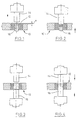
- FIG. 1 and 2 show a die 10, the bore of which forms a mold cavity 12, which is conical in cross section. With the help of such A cavity can be created in the mold cavity 12, e.g. for a cutting insert, as shown in Fig. 5. 5 has a clearance angle.
- the top edge of the mold cavity 12 (die hole) from the top edge of the Matrix 12 has a distance x.
- Above the die 12 is an upper punch 14 and a lower stamp 16 is indicated below the die 10.
- the stamps 14, 16 will be actuated in a suitable manner, preferably with hydraulic press cylinders. These can be controlled (not shown) in such a way that they exert a desired force. They can also be controlled at a speed of one to generate the desired force-time curve. Suitable force measuring devices that are assigned to the punches 14, 16, determine the press forces applied in each case. Path sensors, not shown, determine the positions of the upper and lower stamps 14, 16 during the pressing process.
- the lower punch 16 When the die bore is filled, the lower punch 16 has a predetermined one Filling position. Its position determines the filling quantity. Preferably the position at the beginning somewhat lower than the theoretical filling position for the given one Quantity, so that after filling the lower stamp a certain distance the column can go up so that the filler shoe, not shown, excess material from the top of the die. Then upper stamp 14 and Lower punch 16 moved into the die hole, the upper punch 14 drives so far that it lies on the top of the mold cavity 12 comes. The depth of entry into the die hole therefore corresponds to dimension x. The Lower stamp 16 is also moved to a predetermined position, as shown in Fig. 2 is shown. Then the pressing process takes place.
- the embodiment 3 and FIG. 4 differs from that of FIGS. 1 and 2 in that the bore of the die is cylindrical. That with the help of the procedure manufactured insert has no clearance angle. Incidentally, the Embodiment according to Figures 3 and 4 with the same reference numerals as 1 and 2 provided.
- a predetermined Density are generated.
- the energy or the work done corresponds to that measured press force times the press travel. Therefore, this procedure does not Move according to a predetermined target curve for the pressing force, but to achieve it seen a constant energy input for all compacts. For this heard that the pressing force of the lower punch can be quite different.
- the pressure of the lower punch is determined by the energy input from Upper stamp "traced". This can result in the lower area of the sintered cutting plate 20 has a slightly different density from the upper region prevails. However, this must be accepted if it is guaranteed that upper area of the insert 20 precise dimensions can be achieved.
- the press force curve increases up to a maximum press force P max .
- the integral under this curve corresponds to the energy input E during the pressing process.
- the energy input E is composed of individual increments ⁇ E, and it is easily possible to control the upper punch 14 in such a way that predetermined energy increments are entered. However, the energy ultimately used is less than the energy initially entered because the compact shows a spring-back behavior.
- a kind of hysteresis is formed, as shown in FIG. 6.
- the area between the branches according to the curve. 6 forms the unused energy for the compression of the compact. The energy that results from the area below the lower curve is therefore decisive for the desired density in the upper region of the cutting plate 20.
- the spring behavior can be measured and the unused energy can be determined from the spring travel.
- the spring-open can no longer be used for the respective compact, but only for the next compact.
- the energy entered by the upper punch can be influenced and thus changed until the desired value is reached.
Abstract
Description
- Fig. 1
- zeigt eine Presse zum Verpressen von Metallpulver nach dem erfindungsgemäßen Verfahren vor dem eigentlichen Pressvorgang.
- Fig. 2
- zeigt die Presse nach Fig. 1 während des Pressvorgangs.
- Fig. 3
- zeigt eine abgewandelte Presse zur Durchführung des erfindungsgemäßen Verfahrens.
- Fig. 4
- zeigt die Presse nach Fig. 3 während des Pressvorgangs.
- Fig. 5
- zeigt einen Schnitt durch eine im Sinterverfahren hergestellte Schneidplatte in schematischer Darstellung.
- Fig. 6
- zeigt ein Kraft-Weg-Diagramm zur Illustration des erfindungsgemäßen Verfahrens.
Claims (4)
- Verfahren zur Herstellung von Pressteilen, insbesondere von Schneidplatten aus Hartmetall, durch Pressen von Metallpulver und anschließendes Sintern der Presslinge, bei dem die Presslinge in einer Pulverpresse geformt werden, die eine Matrizenplatte, einen Oberstempel und mindestens einen Unterstempel aufweist, die einer Matrizenbohrung zugeordnet und von einem hydraulischen Pressenzylinder betätigbar sind, wobei den Stempeln Kraftmessvorrichtungen und Wegmessvorrichtungen zugeordnet sind zur Messung der Presskräfte während des Stempelvorschubs bis zu den Endpositionen, dadurch gekennzeichnet, dass für einen Pressling vorgegebener Geometrie und Abmessungen sowie vorgegebenen Materials der Wert für die vom Oberstempel einzubringende Energie gespeichert wird, dass ferner als zweiter Wert die vom Ober- und Unterstempel insgesamt einzutragende Energie gespeichert wird, dass der Vorschub des Oberstempels beendet wird, wenn sein Energieeintrag den vorgegebenen ersten Wert erreicht hat und der Vorschub des Unterstempels nach Maßgabe des Restenergieeintrags erfolgt und beendet wird, wenn die Gesamtenergie den vorgegebenen zweiten Wert erreicht hat.
- Verfahren nach Anspruch 1, dadurch gekennzeichnet, dass der Verlauf des Energieeintrags über einen Pressweg des Oberstempels gespeichert wird und der Vorschub des Oberstempels nach Maßgabe dieses Verlaufs geregelt wird.
- Verfahren nach Anspruch 2, dadurch gekennzeichnet, dass erster und zweiter Wert nur für die zweite Hälfte des Pressweges des Oberstempels gespeichert werden oder nur während der zweiten Hälfte des Pressweges der Energieeintrag des Oberstempels mit dem Energieeintrag von Ober- und Unterstempel verglichen wird.
- Verfahren nach einem der Ansprüche 1 bis 3, dadurch gekennzeichnet, dass nach Beendigung des Pressvorgangs der Auffederweg für den Pressling gemessen wird und aus der Auffederung die nicht zur Verdichtung genutzte Energie berechnet und von dem Gesamtenergieeintrag subtrahiert wird zur Bestimmung des Ist-Energieeintrags für den Pressling und beim nächsten Pressvorgang mindestens ein den Pressvorgang beeinflussender Parameter geändert wird, wenn der Ist-Energieeintrag vom vorgegebenen zweiten Wert abweicht.
Applications Claiming Priority (2)
| Application Number | Priority Date | Filing Date | Title |
|---|---|---|---|
| DE10142772A DE10142772C2 (de) | 2001-08-31 | 2001-08-31 | Verfahren zur Herstellung von Pressteilen in einer Pulverpresse |
| DE10142772 | 2001-08-31 |
Publications (3)
| Publication Number | Publication Date |
|---|---|
| EP1287975A2 true EP1287975A2 (de) | 2003-03-05 |
| EP1287975A3 EP1287975A3 (de) | 2004-01-28 |
| EP1287975B1 EP1287975B1 (de) | 2008-04-02 |
Family
ID=7697312
Family Applications (1)
| Application Number | Title | Priority Date | Filing Date |
|---|---|---|---|
| EP02017011A Expired - Lifetime EP1287975B1 (de) | 2001-08-31 | 2002-07-27 | Verfahren zur Herstellung von Pressteilen in einer Pulverpresse |
Country Status (4)
| Country | Link |
|---|---|
| US (1) | US7211217B2 (de) |
| EP (1) | EP1287975B1 (de) |
| AT (1) | ATE391004T1 (de) |
| DE (2) | DE10142772C2 (de) |
Cited By (2)
| Publication number | Priority date | Publication date | Assignee | Title |
|---|---|---|---|---|
| EP2944457A3 (de) * | 2014-04-10 | 2015-12-16 | Dorst Technologies GmbH & Co. KG | Drucksteuerungsvorrichtung und verfahren zum steuern eines auszugebenden drucks für eine keramik- und/oder metallpulver-presse |
| EP4079427A1 (de) * | 2021-04-22 | 2022-10-26 | GKN Sinter Metals Engineering GmbH | Verfahren zur bestimmung eines parameters eines werkstoffes und presswerkzeug zur herstellung eines grünlings |
Families Citing this family (5)
| Publication number | Priority date | Publication date | Assignee | Title |
|---|---|---|---|---|
| DE102004008322B4 (de) | 2004-02-20 | 2008-11-27 | Fette Gmbh | Pulverpresse |
| JP4918999B2 (ja) | 2006-05-19 | 2012-04-18 | クオリカプス株式会社 | 粉体圧縮成形機及び該成形機を用いた粉体圧縮成形物の連続製造装置 |
| BE1023781B1 (nl) * | 2016-05-18 | 2017-07-24 | Cnh Industrial Belgium Nv | Rechthoekigebalenpers met een verbeterd systeem en een verbeterde regelmethode voor het regelen van de baalvorming |
| CN106079513A (zh) * | 2016-07-21 | 2016-11-09 | 太仓贝斯特机械设备有限公司 | 一种高效率可控式热压成型装置 |
| CN111360248B (zh) * | 2020-03-31 | 2023-04-18 | 珠海精磁新材料技术有限公司 | 一种改进型一模多腔粉末冶金成型模具 |
Citations (7)
| Publication number | Priority date | Publication date | Assignee | Title |
|---|---|---|---|---|
| DE2951716A1 (de) * | 1979-12-19 | 1981-07-02 | Mannesmann AG, 4000 Düsseldorf | Verfahren und vorrichtung zum pressen von formkoerpern |
| US5024811A (en) * | 1989-06-15 | 1991-06-18 | Mannesmann Aktiengesllschaft | Method for manufacturing dimensionally correct compacts |
| DE4209767C1 (de) * | 1992-03-23 | 1993-05-06 | Mannesmann Ag, 4000 Duesseldorf, De | |
| US5699273A (en) * | 1995-01-28 | 1997-12-16 | Wilhelm Fette Gmbh | Method and apparatus for determining the force-displacement diagram of the pairs of punches of a rotary pelleting machine |
| US6074584A (en) * | 1997-04-24 | 2000-06-13 | Wilhelm Fette Gmbh | Method and device for manufacturing pressed parts from hard metal, ceramic, sintered metal or likewise |
| DE19958999A1 (de) * | 1999-12-08 | 2001-04-26 | Henkel Kgaa | Verfahren und Vorrichtung zur Regelung von Tablettenpressen |
| EP1129802A2 (de) * | 2000-03-04 | 2001-09-05 | Wilhelm Fette GmbH | Verfahren zur Steuerung der Pressskraft beim Pressen von Metallpulver |
Family Cites Families (20)
| Publication number | Priority date | Publication date | Assignee | Title |
|---|---|---|---|---|
| US3687586A (en) * | 1970-04-22 | 1972-08-29 | Tamagawa Kikai Kinzoku Kk | Powder-forming press |
| US3640654A (en) * | 1970-06-25 | 1972-02-08 | Wolverine Pentronix | Die and punch assembly for compacting powder and method of assembly |
| US3826599A (en) * | 1972-06-01 | 1974-07-30 | Wolverine Pentronix | Adjusting mechanism and process for powder compacting press |
| US4260346A (en) * | 1979-10-09 | 1981-04-07 | Anderson Jr Raymond B | Press assembly for powder material |
| US4443171A (en) * | 1982-04-14 | 1984-04-17 | Wesjay, Inc. | Multi-motion mechanical press |
| US4946634A (en) * | 1987-04-16 | 1990-08-07 | Gte Products Corporation | Powder compacting press to control green density distribution in parts |
| DE4009608A1 (de) * | 1989-04-07 | 1990-10-11 | Laeis & Bucher Gmbh | Verfahren zur herstellung von formlingen aus koernigem und pulverfoermigem werkstoff und vorrichtung zur durchfuehrung des verfahrens |
| JPH07115233B2 (ja) * | 1990-08-10 | 1995-12-13 | 株式会社ヨシツカ精機 | 粉末成形プレス |
| JP3169247B2 (ja) * | 1991-12-03 | 2001-05-21 | 株式会社石井工作研究所 | プレス機械の加圧力自動制御方法とその装置 |
| GB9206526D0 (en) * | 1992-03-25 | 1992-05-06 | Komage Gellner & Co | Press apparatus |
| US5391069A (en) * | 1993-06-10 | 1995-02-21 | Bendzick; Ervin J. | Apparatus for compacting metal shavings |
| US5547360A (en) * | 1994-03-17 | 1996-08-20 | Tamagawa Machinery Co., Ltd. | Powder molding press |
| DE4428842C1 (de) * | 1994-08-02 | 1996-01-18 | Mannesmann Ag | Vorrichtung zur Herstellung von Preßkörpern |
| TW287975B (en) * | 1995-11-16 | 1996-10-11 | Honda Motor Co Ltd | Method of and apparatus for manufacturing pressed powder body |
| JP3059406B2 (ja) * | 1997-08-27 | 2000-07-04 | 本田技研工業株式会社 | 圧粉成形装置 |
| US5989487A (en) * | 1999-03-23 | 1999-11-23 | Materials Modification, Inc. | Apparatus for bonding a particle material to near theoretical density |
| JP3717714B2 (ja) * | 1999-07-05 | 2005-11-16 | 本田技研工業株式会社 | はすば歯車の圧粉成形方法 |
| US6477945B1 (en) * | 1999-09-07 | 2002-11-12 | Aida Engineering, Ltd. | Double-action mechanical press |
| SE515822C2 (sv) * | 1999-12-30 | 2001-10-15 | Skf Nova Ab | Metod och anordning för kompaktering av pulvermetallkroppar |
| US6531090B2 (en) * | 2000-02-17 | 2003-03-11 | Sumitomo Special Metals Co., Ltd. | Method for producing powder compact and method for manufacturing magnet |
-
2001
- 2001-08-31 DE DE10142772A patent/DE10142772C2/de not_active Expired - Fee Related
-
2002
- 2002-07-27 AT AT02017011T patent/ATE391004T1/de not_active IP Right Cessation
- 2002-07-27 DE DE50212003T patent/DE50212003D1/de not_active Expired - Fee Related
- 2002-07-27 EP EP02017011A patent/EP1287975B1/de not_active Expired - Lifetime
- 2002-08-22 US US10/225,747 patent/US7211217B2/en not_active Expired - Fee Related
Patent Citations (7)
| Publication number | Priority date | Publication date | Assignee | Title |
|---|---|---|---|---|
| DE2951716A1 (de) * | 1979-12-19 | 1981-07-02 | Mannesmann AG, 4000 Düsseldorf | Verfahren und vorrichtung zum pressen von formkoerpern |
| US5024811A (en) * | 1989-06-15 | 1991-06-18 | Mannesmann Aktiengesllschaft | Method for manufacturing dimensionally correct compacts |
| DE4209767C1 (de) * | 1992-03-23 | 1993-05-06 | Mannesmann Ag, 4000 Duesseldorf, De | |
| US5699273A (en) * | 1995-01-28 | 1997-12-16 | Wilhelm Fette Gmbh | Method and apparatus for determining the force-displacement diagram of the pairs of punches of a rotary pelleting machine |
| US6074584A (en) * | 1997-04-24 | 2000-06-13 | Wilhelm Fette Gmbh | Method and device for manufacturing pressed parts from hard metal, ceramic, sintered metal or likewise |
| DE19958999A1 (de) * | 1999-12-08 | 2001-04-26 | Henkel Kgaa | Verfahren und Vorrichtung zur Regelung von Tablettenpressen |
| EP1129802A2 (de) * | 2000-03-04 | 2001-09-05 | Wilhelm Fette GmbH | Verfahren zur Steuerung der Pressskraft beim Pressen von Metallpulver |
Cited By (2)
| Publication number | Priority date | Publication date | Assignee | Title |
|---|---|---|---|---|
| EP2944457A3 (de) * | 2014-04-10 | 2015-12-16 | Dorst Technologies GmbH & Co. KG | Drucksteuerungsvorrichtung und verfahren zum steuern eines auszugebenden drucks für eine keramik- und/oder metallpulver-presse |
| EP4079427A1 (de) * | 2021-04-22 | 2022-10-26 | GKN Sinter Metals Engineering GmbH | Verfahren zur bestimmung eines parameters eines werkstoffes und presswerkzeug zur herstellung eines grünlings |
Also Published As
| Publication number | Publication date |
|---|---|
| EP1287975A3 (de) | 2004-01-28 |
| US7211217B2 (en) | 2007-05-01 |
| US20030049147A1 (en) | 2003-03-13 |
| DE10142772A1 (de) | 2003-03-27 |
| EP1287975B1 (de) | 2008-04-02 |
| DE10142772C2 (de) | 2003-09-25 |
| ATE391004T1 (de) | 2008-04-15 |
| DE50212003D1 (de) | 2008-05-15 |
Similar Documents
| Publication | Publication Date | Title |
|---|---|---|
| EP0873855B1 (de) | Verfahren und Vorrichtung zur Herstellung von Presslingen aus Hartmetall, Keramik, Sintermetall oder dergleichen | |
| DE69833396T2 (de) | Hydraulische Presse zur Herstellung von Metallplatten | |
| EP1566231B1 (de) | Pulverpresse | |
| DE102015109805A1 (de) | Herstellen von qualitativ harten Formstoffformen für den Metallguss (Verfahren und Vorrichtung) | |
| DE4209767C1 (de) | ||
| EP1852247A2 (de) | Presse zur Herstellung von Preßlingen aus Pulvermaterial | |
| EP0403040A2 (de) | Verfahren und Vorrichtung zur Herstellung masshaltiger Presslinge | |
| EP0353479B1 (de) | Verfahren und Vorrichtung zur Verminderung der Pressenbelastung einer mit Festanschlägen ausgerüsteten Schnittpresse | |
| DE10142772C2 (de) | Verfahren zur Herstellung von Pressteilen in einer Pulverpresse | |
| EP1287978A2 (de) | Verfahren und Vorrichtung zum Pressen von Metallpulver zu einem Pressling | |
| EP1129802B2 (de) | Verfahren zur Steuerung der Pressskraft beim Pressen von Metallpulver | |
| EP0367035B1 (de) | Presse oder Stanze | |
| DE10142773C1 (de) | Hydraulische Presse zum Pressen von Metallpulver | |
| EP0698481A1 (de) | Fuzzysteuerungsverfahren zur Qualitätssicherung bei der Tablettenherstellung | |
| DE19903417B4 (de) | Verfahren zum Befüllen einer Hydraulikpresse mit Pulvern | |
| EP1277564A2 (de) | Verfahren zum Verpressen von Pulvermaterial | |
| EP0428780B1 (de) | Stanzpresse mit Korrekturwerteingabe für die Eintauchtiefe und die Vorschublänge | |
| DE102004012858B4 (de) | Verfahren und Einrichtung zur Wälzkörperherstellung | |
| DE10142623C2 (de) | Verfahren und Vorrichtung zur Minimierung der Streuung der maximalen Presskräfte in einer Pulverpresse | |
| EP0401501B1 (de) | Verfahren zur Beeinflussung der Fliessfrontbewegung beim Auspressen von Pressmassen und Einrichtung zur Durchführung des Verfahrens | |
| DE19545753B4 (de) | Regelung von Rahmenposition und Preßdruck in Formanlagen | |
| DE19955196A1 (de) | Verfahren zum Konstanthalten der Bruchhärte von Tabletten | |
| DE102017119342A1 (de) | Verfahren zur Steuerung einer Metall- oder Keramikpulverpresse mit automatischer Trajektorien-Generierung |
Legal Events
| Date | Code | Title | Description |
|---|---|---|---|
| PUAI | Public reference made under article 153(3) epc to a published international application that has entered the european phase |
Free format text: ORIGINAL CODE: 0009012 |
|
| AK | Designated contracting states |
Kind code of ref document: A2 Designated state(s): AT BE BG CH CY CZ DE DK EE ES FI FR GB GR IE IT LI LU MC NL PT SE SK TR |
|
| AX | Request for extension of the european patent |
Extension state: AL LT LV MK RO SI |
|
| PUAL | Search report despatched |
Free format text: ORIGINAL CODE: 0009013 |
|
| AK | Designated contracting states |
Kind code of ref document: A3 Designated state(s): AT BE BG CH CY CZ DE DK EE ES FI FR GB GR IE IT LI LU MC NL PT SE SK TR |
|
| AX | Request for extension of the european patent |
Extension state: AL LT LV MK RO SI |
|
| RIC1 | Information provided on ipc code assigned before grant |
Ipc: 7B 30B 11/00 A Ipc: 7B 22F 3/02 B Ipc: 7B 30B 15/22 B |
|
| 17P | Request for examination filed |
Effective date: 20031218 |
|
| 17Q | First examination report despatched |
Effective date: 20040330 |
|
| AKX | Designation fees paid |
Designated state(s): AT BE BG CH CY CZ DE DK EE ES FI FR GB GR IE IT LI LU MC NL PT SE SK TR |
|
| GRAP | Despatch of communication of intention to grant a patent |
Free format text: ORIGINAL CODE: EPIDOSNIGR1 |
|
| GRAS | Grant fee paid |
Free format text: ORIGINAL CODE: EPIDOSNIGR3 |
|
| GRAA | (expected) grant |
Free format text: ORIGINAL CODE: 0009210 |
|
| AK | Designated contracting states |
Kind code of ref document: B1 Designated state(s): AT BE BG CH CY CZ DE DK EE ES FI FR GB GR IE IT LI LU MC NL PT SE SK TR |
|
| REG | Reference to a national code |
Ref country code: GB Ref legal event code: FG4D Free format text: NOT ENGLISH |
|
| REG | Reference to a national code |
Ref country code: IE Ref legal event code: FG4D Free format text: LANGUAGE OF EP DOCUMENT: GERMAN Ref country code: CH Ref legal event code: EP |
|
| REF | Corresponds to: |
Ref document number: 50212003 Country of ref document: DE Date of ref document: 20080515 Kind code of ref document: P |
|
| REG | Reference to a national code |
Ref country code: SE Ref legal event code: TRGR |
|
| REG | Reference to a national code |
Ref country code: CH Ref legal event code: NV Representative=s name: ISLER & PEDRAZZINI AG |
|
| NLV1 | Nl: lapsed or annulled due to failure to fulfill the requirements of art. 29p and 29m of the patents act | ||
| REG | Reference to a national code |
Ref country code: IE Ref legal event code: FD4D |
|
| PG25 | Lapsed in a contracting state [announced via postgrant information from national office to epo] |
Ref country code: PT Free format text: LAPSE BECAUSE OF FAILURE TO SUBMIT A TRANSLATION OF THE DESCRIPTION OR TO PAY THE FEE WITHIN THE PRESCRIBED TIME-LIMIT Effective date: 20080902 Ref country code: NL Free format text: LAPSE BECAUSE OF FAILURE TO SUBMIT A TRANSLATION OF THE DESCRIPTION OR TO PAY THE FEE WITHIN THE PRESCRIBED TIME-LIMIT Effective date: 20080402 Ref country code: FI Free format text: LAPSE BECAUSE OF FAILURE TO SUBMIT A TRANSLATION OF THE DESCRIPTION OR TO PAY THE FEE WITHIN THE PRESCRIBED TIME-LIMIT Effective date: 20080402 Ref country code: ES Free format text: LAPSE BECAUSE OF FAILURE TO SUBMIT A TRANSLATION OF THE DESCRIPTION OR TO PAY THE FEE WITHIN THE PRESCRIBED TIME-LIMIT Effective date: 20080713 Ref country code: BG Free format text: LAPSE BECAUSE OF FAILURE TO SUBMIT A TRANSLATION OF THE DESCRIPTION OR TO PAY THE FEE WITHIN THE PRESCRIBED TIME-LIMIT Effective date: 20080702 |
|
| ET | Fr: translation filed | ||
| PG25 | Lapsed in a contracting state [announced via postgrant information from national office to epo] |
Ref country code: CZ Free format text: LAPSE BECAUSE OF FAILURE TO SUBMIT A TRANSLATION OF THE DESCRIPTION OR TO PAY THE FEE WITHIN THE PRESCRIBED TIME-LIMIT Effective date: 20080402 Ref country code: DK Free format text: LAPSE BECAUSE OF FAILURE TO SUBMIT A TRANSLATION OF THE DESCRIPTION OR TO PAY THE FEE WITHIN THE PRESCRIBED TIME-LIMIT Effective date: 20080402 Ref country code: IE Free format text: LAPSE BECAUSE OF FAILURE TO SUBMIT A TRANSLATION OF THE DESCRIPTION OR TO PAY THE FEE WITHIN THE PRESCRIBED TIME-LIMIT Effective date: 20080402 |
|
| PLBE | No opposition filed within time limit |
Free format text: ORIGINAL CODE: 0009261 |
|
| STAA | Information on the status of an ep patent application or granted ep patent |
Free format text: STATUS: NO OPPOSITION FILED WITHIN TIME LIMIT |
|
| PG25 | Lapsed in a contracting state [announced via postgrant information from national office to epo] |
Ref country code: SK Free format text: LAPSE BECAUSE OF FAILURE TO SUBMIT A TRANSLATION OF THE DESCRIPTION OR TO PAY THE FEE WITHIN THE PRESCRIBED TIME-LIMIT Effective date: 20080402 |
|
| 26N | No opposition filed |
Effective date: 20090106 |
|
| PG25 | Lapsed in a contracting state [announced via postgrant information from national office to epo] |
Ref country code: MC Free format text: LAPSE BECAUSE OF NON-PAYMENT OF DUE FEES Effective date: 20080731 |
|
| PG25 | Lapsed in a contracting state [announced via postgrant information from national office to epo] |
Ref country code: EE Free format text: LAPSE BECAUSE OF FAILURE TO SUBMIT A TRANSLATION OF THE DESCRIPTION OR TO PAY THE FEE WITHIN THE PRESCRIBED TIME-LIMIT Effective date: 20080402 |
|
| PG25 | Lapsed in a contracting state [announced via postgrant information from national office to epo] |
Ref country code: CY Free format text: LAPSE BECAUSE OF FAILURE TO SUBMIT A TRANSLATION OF THE DESCRIPTION OR TO PAY THE FEE WITHIN THE PRESCRIBED TIME-LIMIT Effective date: 20080402 |
|
| PGFP | Annual fee paid to national office [announced via postgrant information from national office to epo] |
Ref country code: FR Payment date: 20090729 Year of fee payment: 8 |
|
| PGFP | Annual fee paid to national office [announced via postgrant information from national office to epo] |
Ref country code: AT Payment date: 20090729 Year of fee payment: 8 Ref country code: CH Payment date: 20090730 Year of fee payment: 8 Ref country code: DE Payment date: 20090909 Year of fee payment: 8 Ref country code: GB Payment date: 20090701 Year of fee payment: 8 Ref country code: LU Payment date: 20090710 Year of fee payment: 8 Ref country code: SE Payment date: 20090730 Year of fee payment: 8 |
|
| PGFP | Annual fee paid to national office [announced via postgrant information from national office to epo] |
Ref country code: IT Payment date: 20090723 Year of fee payment: 8 |
|
| PG25 | Lapsed in a contracting state [announced via postgrant information from national office to epo] |
Ref country code: BE Free format text: LAPSE BECAUSE OF NON-PAYMENT OF DUE FEES Effective date: 20080731 |
|
| PG25 | Lapsed in a contracting state [announced via postgrant information from national office to epo] |
Ref country code: TR Free format text: LAPSE BECAUSE OF FAILURE TO SUBMIT A TRANSLATION OF THE DESCRIPTION OR TO PAY THE FEE WITHIN THE PRESCRIBED TIME-LIMIT Effective date: 20080402 |
|
| PG25 | Lapsed in a contracting state [announced via postgrant information from national office to epo] |
Ref country code: GR Free format text: LAPSE BECAUSE OF FAILURE TO SUBMIT A TRANSLATION OF THE DESCRIPTION OR TO PAY THE FEE WITHIN THE PRESCRIBED TIME-LIMIT Effective date: 20080703 |
|
| REG | Reference to a national code |
Ref country code: CH Ref legal event code: PL |
|
| GBPC | Gb: european patent ceased through non-payment of renewal fee |
Effective date: 20100727 |
|
| REG | Reference to a national code |
Ref country code: FR Ref legal event code: ST Effective date: 20110331 |
|
| PG25 | Lapsed in a contracting state [announced via postgrant information from national office to epo] |
Ref country code: DE Free format text: LAPSE BECAUSE OF NON-PAYMENT OF DUE FEES Effective date: 20110201 Ref country code: LI Free format text: LAPSE BECAUSE OF NON-PAYMENT OF DUE FEES Effective date: 20100731 Ref country code: CH Free format text: LAPSE BECAUSE OF NON-PAYMENT OF DUE FEES Effective date: 20100731 |
|
| REG | Reference to a national code |
Ref country code: DE Ref legal event code: R119 Ref document number: 50212003 Country of ref document: DE Effective date: 20110201 |
|
| PG25 | Lapsed in a contracting state [announced via postgrant information from national office to epo] |
Ref country code: FR Free format text: LAPSE BECAUSE OF NON-PAYMENT OF DUE FEES Effective date: 20100802 Ref country code: IT Free format text: LAPSE BECAUSE OF NON-PAYMENT OF DUE FEES Effective date: 20100727 Ref country code: AT Free format text: LAPSE BECAUSE OF NON-PAYMENT OF DUE FEES Effective date: 20100727 |
|
| PG25 | Lapsed in a contracting state [announced via postgrant information from national office to epo] |
Ref country code: GB Free format text: LAPSE BECAUSE OF NON-PAYMENT OF DUE FEES Effective date: 20100727 |
|
| PG25 | Lapsed in a contracting state [announced via postgrant information from national office to epo] |
Ref country code: SE Free format text: LAPSE BECAUSE OF NON-PAYMENT OF DUE FEES Effective date: 20100728 Ref country code: LU Free format text: LAPSE BECAUSE OF NON-PAYMENT OF DUE FEES Effective date: 20100727 |