EP1129802A2 - Verfahren zur Steuerung der Pressskraft beim Pressen von Metallpulver - Google Patents
Verfahren zur Steuerung der Pressskraft beim Pressen von Metallpulver Download PDFInfo
- Publication number
- EP1129802A2 EP1129802A2 EP01104107A EP01104107A EP1129802A2 EP 1129802 A2 EP1129802 A2 EP 1129802A2 EP 01104107 A EP01104107 A EP 01104107A EP 01104107 A EP01104107 A EP 01104107A EP 1129802 A2 EP1129802 A2 EP 1129802A2
- Authority
- EP
- European Patent Office
- Prior art keywords
- pressing force
- predetermined
- stamp
- punch
- die
- Prior art date
- Legal status (The legal status is an assumption and is not a legal conclusion. Google has not performed a legal analysis and makes no representation as to the accuracy of the status listed.)
- Granted
Links
Images

Classifications
-
- B—PERFORMING OPERATIONS; TRANSPORTING
- B22—CASTING; POWDER METALLURGY
- B22F—WORKING METALLIC POWDER; MANUFACTURE OF ARTICLES FROM METALLIC POWDER; MAKING METALLIC POWDER; APPARATUS OR DEVICES SPECIALLY ADAPTED FOR METALLIC POWDER
- B22F3/00—Manufacture of workpieces or articles from metallic powder characterised by the manner of compacting or sintering; Apparatus specially adapted therefor ; Presses and furnaces
- B22F3/02—Compacting only
-
- B—PERFORMING OPERATIONS; TRANSPORTING
- B30—PRESSES
- B30B—PRESSES IN GENERAL
- B30B11/00—Presses specially adapted for forming shaped articles from material in particulate or plastic state, e.g. briquetting presses, tabletting presses
- B30B11/005—Control arrangements
-
- B—PERFORMING OPERATIONS; TRANSPORTING
- B22—CASTING; POWDER METALLURGY
- B22F—WORKING METALLIC POWDER; MANUFACTURE OF ARTICLES FROM METALLIC POWDER; MAKING METALLIC POWDER; APPARATUS OR DEVICES SPECIALLY ADAPTED FOR METALLIC POWDER
- B22F5/00—Manufacture of workpieces or articles from metallic powder characterised by the special shape of the product
- B22F2005/001—Cutting tools, earth boring or grinding tool other than table ware
-
- B—PERFORMING OPERATIONS; TRANSPORTING
- B22—CASTING; POWDER METALLURGY
- B22F—WORKING METALLIC POWDER; MANUFACTURE OF ARTICLES FROM METALLIC POWDER; MAKING METALLIC POWDER; APPARATUS OR DEVICES SPECIALLY ADAPTED FOR METALLIC POWDER
- B22F2998/00—Supplementary information concerning processes or compositions relating to powder metallurgy
-
- B—PERFORMING OPERATIONS; TRANSPORTING
- B22—CASTING; POWDER METALLURGY
- B22F—WORKING METALLIC POWDER; MANUFACTURE OF ARTICLES FROM METALLIC POWDER; MAKING METALLIC POWDER; APPARATUS OR DEVICES SPECIALLY ADAPTED FOR METALLIC POWDER
- B22F2999/00—Aspects linked to processes or compositions used in powder metallurgy
Definitions
- the invention relates to a method for producing pressed parts, in particular of carbide inserts, by pressing metal powder and subsequent sintering of the compact according to claim 1.
- compliance is one predetermined total height between insert seat and at least one cutting edge, which has a predetermined distance from the insert seat.
- the invention has for its object a method for producing Carbide inserts by pressing and sintering the compact, in particular of indexable inserts, to create that easier than the last described is known method and nevertheless leads to excellent results.
- the invention also begins with one predetermined amount of metal powder filled into the die hole, the Lower stamp assumes a filling position. If necessary, the First move the lower stamp to a slightly lower position, so that a slight Excess quantity is filled, after which the lower stamp is the final one Fills the filling position and with the help of the filling shoe from the die hole ejected rest is stripped. Then the upper stamp and move the lower punch into a predetermined first or second position, whereby a certain pressing force can already be applied. Is it one Pressed part, which is intended for a cutting plate with clearance angle, corresponds to the position the upper stamp at the approached second position z. B. the top of the Compacts.
- the lower and upper stamps are adjusted further, however, in the case of a compact with a clearance angle, only the lower stamp is adjusted.
- the pressing forces are continuous measured, whereby the infeed movement of the lower and upper stamps is ended, when the pressing force has reached a predetermined value. Even with adjustment both stamps, it may be sufficient to measure the pressing force on the lower stamp alone and to end the adjustment movement when the measured pressing force reaches the predetermined one Has reached value.
- the predetermined value for the pressing force is determined by previous tests determined. First of all, it is determined what compaction the metal powder should be obtained in order to then be subjected to the sintering process. Then it is examined how large the filling quantity must be, so that when a predetermined pressing force reproducibly reaches a certain height of the compact becomes. Is therefore in the method according to the invention at a predetermined Pressing force switched off, then it can be assumed that the predetermined Height of the compact has been reached. This way, too certain filling fluctuations reached a predetermined density of the compact.
- the lower stamp is adjusted and / or upper stamp from the first or second position along a predetermined Target curve for the pressing force, the target curve being the dependence of the pressing force reproduces from time. In this way it is possible to get the final one to approach the desired pressing force values in a regulating manner.
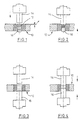
- FIG. 1 and 2 show a die 10, the bore of which forms a mold cavity 12, which is conical in cross section. With the help of such Mold cavity 12 can be formed as a compact Cutting plate, for example an indexable insert with clearance angle used becomes.
- the upper edge of the mold cavity 12 has from the upper edge of the die 12 a distance x.
- Above the die 12 is an upper punch 14 and below the die 10 a lower stamp 16 indicated.
- the stamps 14, 16 are in actuated in a suitable manner, preferably with the aid of hydraulic cylinders. This are controllable (not shown) so that they exert a desired force. Moreover they can be controlled in their speed, e.g. Legs to generate the desired force-time curve.
- the lower stamp 16 has a predetermined filling position.
- the lower stamp 16 is also set to a predetermined one Move position, as shown in Fig. 2. Here takes place a pressing process is already taking place. Subsequently, the lower stamp 16 continues proceed until a specified pressing force has been reached.
- the pressing force is like this dimensioned that the height of the to be molded for a given filling quantity Compacts (not shown) corresponds to the target height. Is the target height or target thickness has not yet been reached, it is necessary after sintering, the so shaped Edit plate to the desired size, e.g. B. to grind. Therefore it is too ensure that in the described method it is avoided that a compact is shaped with undersize.
- FIGS. 3 and 4 differs from that according to the figures 1 and 2 only in that the bore of the die is cylindrical. With the help cutting insert produced by the method therefore has no clearance angle. in the rest of the embodiment of Figures 3 and 4 with the same reference numerals like Figure 1 provided.
- Line 20 in FIG. 5 indicates the upper edge of the die.
- the thick undressed Curve 22 indicates the position profile of an upper punch and the thickly drawn Curve 24 after a lower stamp, for example the stamp 14, 16 3 and 4.
- the solid line 26 indicates the course of the position of the filling shoe.
- the lower stamp has the position a corresponding to the top edge of the die and the top stamp is clearly located above the top edge of the die.
- the filling shoe is over the die, and the lower punch moves into a first filling position b, during which one The die hole is filled with hard metal powder, as indicated at 28.
- the filling is finished at c.
- the lower stamp moves a little up to position d, which is the final fill position, d. H.
- the powder column in the die hole corresponds to the specified filling quantity. Perhaps Excess material above the upper edge 20 of the die is then removed from the filling shoe stripped. The filling shoe then moves to its starting position, and the upper stamp moves to position P2, while the lower stamp at the same time moves back a little to prevent the upper punch from powder material presses out of the die hole laterally. Then the upper stamp move to position P3, with the lower punch the one previously taken Still maintains position. Now the pressing process begins, with the position P4 of upper and lower stamps via a predetermined path that the stamp cover, can be started. With the help of suitable signposts it is possible to provide a precise path control for the stamp. Here takes place a more or less significant compression of the powder material is already taking place.
Landscapes
- Engineering & Computer Science (AREA)
- Mechanical Engineering (AREA)
- Manufacturing & Machinery (AREA)
- Powder Metallurgy (AREA)
- Coating Apparatus (AREA)
- Punching Or Piercing (AREA)
Abstract
- Einfüllen einer vorgegebenen Menge an Metallpulver in die Matrizenbohrung, wobei der Unterstempel eine vorgegebene Einfüllposition in der Matrizenbohrung aufweist,
- Verstellen des Unterstempels und des Oberstempels in eine vorgegebene erste bzw. zweite Position,
- weiteres Verstellen des Unterstempels und gegebenenfalls des Oberstempels und gleichzeitiges Messen der Preßkraft mindestens des Unterstempels, wobei die Verstellung von Unterstempel bzw. Oberstempel entlang einer vorgegebenen Sollkurve für die Preßkraft erfolgt
- Beenden der Zustellbewegung von Unterstempel und gegebenenfalls des Oberstempels, wenn ein vorgegebener Wert für die Preßkraft erreicht wird.
Description
- Fig. 1
- zeigt eine Presse zum Verpressen von Metallpulver nach dem erfindungsgemäßen Verfahren und von dem eigentlichen Preßvorgang.
- Fig. 2
- zeigt die Presse nach Fig. 1 während des Preßvorgangs.
- Fig. 3
- zeigt eine abgewandelte Presse zur Durchführung des erfindungsgemäßen Verfahrens oder den Preßvorgang.
- Fig. 4
- zeigt die Presse nach Fig. 3 während des Preßvorgangs.
- Fig. 5
- zeigt ein Bewegdiagramm für die Preßstempel der Presse nach den Figuren 3 und 4.
Claims (3)
- Verfahren zur Herstellung von Preßteilen, insbesondere von Schneidplatten aus Hartmetall durch Pressen von Metallpulver und anschließendes Sintern des Preßlings, insbesondere von Wendeschneidplatten, die eine Sitzfläche und mindestens eine annähernd parallel zur Sitzfläche verlaufende Schneidkante aufweisen, die von der Sitzfläche einen vorgegebenen Abstand hat, mit Hilfe einer eine Matrize und einen Ober- und einen Unterstempel aufweisenden Presse, mit den Schritten:Einfüllen einer vorgegebenen Menge an Metallpulver in die Matrizenbohrung, wobei der Unterstempel eine vorgegebene Einfüllposition in der Matrizenbohrung aufweist,Verstellen des Unterstempels und des Oberstempels in eine vorgegebene erste bzw. zweite Position,weiteres Verstellen des Unterstempels und gegebenenfalls des Oberstempels und gleichzeitiges Messen der Preßkraft mindestens des Unterstempels, wobei die Verstellung von Unterstempel bzw. Oberstempel entlang einer vorgegebenen Sollkurve für die Preßkraft erfolgtBeenden der Zustellbewegung von Unterstempel und gegebenenfalls des Oberstempels, wenn ein vorgegebener Wert für die Preßkraft erreicht wird.
- Verfahren nach Anspruch 1, dadurch gekennzeichnet, daß bei Schneidplatten ohne Freiwinkel Unter- und Oberstempel ab der ersten bzw. zweiten Position bis zu einem vorgegebenen Wert für die Preßkraft oder entlang einer Sollkurve für die Preßkraft verstellt werden.
- Verfahren nach Anspruch 1 und 2, dadurch gekennzeichnet, daß bei Schneidplatten mit Freiwinkel nur der Unterstempel ab der ersten Position bis zu einem vorgegebenen Preßkraftwert bzw. entlang einer Sollkurve für die Preßkraft verfahren wird.
Applications Claiming Priority (2)
| Application Number | Priority Date | Filing Date | Title |
|---|---|---|---|
| DE10010671 | 2000-03-04 | ||
| DE10010671A DE10010671C2 (de) | 2000-03-04 | 2000-03-04 | Verfahren zur Herstellung von Preßteilen durch Pressen von Metallpulver und anschließendes Sintern des Preßlings |
Publications (4)
| Publication Number | Publication Date |
|---|---|
| EP1129802A2 true EP1129802A2 (de) | 2001-09-05 |
| EP1129802A3 EP1129802A3 (de) | 2004-05-06 |
| EP1129802B1 EP1129802B1 (de) | 2007-03-14 |
| EP1129802B2 EP1129802B2 (de) | 2010-08-11 |
Family
ID=7633551
Family Applications (1)
| Application Number | Title | Priority Date | Filing Date |
|---|---|---|---|
| EP01104107A Expired - Lifetime EP1129802B2 (de) | 2000-03-04 | 2001-02-21 | Verfahren zur Steuerung der Pressskraft beim Pressen von Metallpulver |
Country Status (4)
| Country | Link |
|---|---|
| US (1) | US6562291B2 (de) |
| EP (1) | EP1129802B2 (de) |
| AT (1) | ATE356681T1 (de) |
| DE (2) | DE10010671C2 (de) |
Cited By (3)
| Publication number | Priority date | Publication date | Assignee | Title |
|---|---|---|---|---|
| EP1287975A3 (de) * | 2001-08-31 | 2004-01-28 | Fette GmbH | Verfahren zur Herstellung von Pressteilen in einer Pulverpresse |
| EP2750151A4 (de) * | 2011-07-27 | 2015-03-11 | Sumitomo Electric Industries | Gepresster pulverpressling |
| DE102010015016B4 (de) * | 2009-04-24 | 2016-06-09 | Sms Group Gmbh | Pulverpresse |
Families Citing this family (9)
| Publication number | Priority date | Publication date | Assignee | Title |
|---|---|---|---|---|
| DE10135283C2 (de) * | 2001-07-19 | 2003-09-18 | Fette Wilhelm Gmbh | Verfahren zum Verpressen von Pulvermaterial |
| DE102004008322B4 (de) * | 2004-02-20 | 2008-11-27 | Fette Gmbh | Pulverpresse |
| WO2008114827A1 (ja) * | 2007-03-20 | 2008-09-25 | Tungaloy Corporation | スローアウェイチップの圧縮成形方法 |
| DE102012019312A1 (de) * | 2012-10-01 | 2014-04-03 | Dorst Technologies Gmbh & Co. Kg | Verfahren zum Steuern einer Keramik- und/oder Metallpulver-Presse bzw. Keramik- und/oder Metallpulver-Presse |
| MA42058A (fr) * | 2015-05-07 | 2018-03-14 | Thermal Tech Llc | Appareil de frittage par compression comprenant des mâchoires opposées protégées |
| DE102017004803A1 (de) | 2017-05-18 | 2018-11-22 | Cosateq Gmbh | Verfahren zum Betrieb einer Pulverpresse mit Lagenregelung und Pulverpresse zur Ausführung des Verfahrens |
| DE102017119342A1 (de) | 2017-08-24 | 2019-02-28 | COSATEQ GmbH & Co. KG | Verfahren zur Steuerung einer Metall- oder Keramikpulverpresse mit automatischer Trajektorien-Generierung |
| SE546938C2 (en) | 2019-12-17 | 2025-03-11 | Kennametal Inc | A method forforming a densified green article by subjecting a green article, formed by additive manufacturing techniques, and a powder pressure transfer media to cold or warm isostatic pressing |
| EP4079427A1 (de) * | 2021-04-22 | 2022-10-26 | GKN Sinter Metals Engineering GmbH | Verfahren zur bestimmung eines parameters eines werkstoffes und presswerkzeug zur herstellung eines grünlings |
Family Cites Families (9)
| Publication number | Priority date | Publication date | Assignee | Title |
|---|---|---|---|---|
| US4000231A (en) * | 1974-09-16 | 1976-12-28 | Hydramet American Inc. | Method for compacting powders |
| DE2825253A1 (de) † | 1978-06-08 | 1979-12-13 | Nitrochemie Gmbh | Hydraulische pulverpresse |
| SE460460B (sv) † | 1983-07-01 | 1989-10-16 | Convey Teknik Ab | Foerfarande och anordning foer reglerad pressning av pulvermaterial |
| DE3715077A1 (de) † | 1987-05-06 | 1988-12-01 | Netzsch Maschinenfabrik | Verfahren zum steuern einer presse |
| JP2519498B2 (ja) * | 1988-01-16 | 1996-07-31 | ファナック株式会社 | 電動式粉末成形機 |
| DE3919821C2 (de) * | 1989-06-15 | 1994-04-07 | Mannesmann Ag | Verfahren und Vorrichtung zum Herstellen von maßhaltigen Preßlingen |
| DE4209767C1 (de) * | 1992-03-23 | 1993-05-06 | Mannesmann Ag, 4000 Duesseldorf, De | |
| US5547360A (en) * | 1994-03-17 | 1996-08-20 | Tamagawa Machinery Co., Ltd. | Powder molding press |
| DE19717217C2 (de) * | 1997-04-24 | 1999-12-02 | Fette Wilhelm Gmbh | Verfahren und Vorrichtung zur Herstellung von Preßlingen aus Hartmetall, Keramik, Sintermetall oder dergleichen |
-
2000
- 2000-03-04 DE DE10010671A patent/DE10010671C2/de not_active Revoked
-
2001
- 2001-02-21 AT AT01104107T patent/ATE356681T1/de active
- 2001-02-21 EP EP01104107A patent/EP1129802B2/de not_active Expired - Lifetime
- 2001-02-21 DE DE50112176T patent/DE50112176D1/de not_active Expired - Lifetime
- 2001-03-02 US US09/798,802 patent/US6562291B2/en not_active Expired - Lifetime
Cited By (4)
| Publication number | Priority date | Publication date | Assignee | Title |
|---|---|---|---|---|
| EP1287975A3 (de) * | 2001-08-31 | 2004-01-28 | Fette GmbH | Verfahren zur Herstellung von Pressteilen in einer Pulverpresse |
| DE102010015016B4 (de) * | 2009-04-24 | 2016-06-09 | Sms Group Gmbh | Pulverpresse |
| EP2750151A4 (de) * | 2011-07-27 | 2015-03-11 | Sumitomo Electric Industries | Gepresster pulverpressling |
| US9251946B2 (en) | 2011-07-27 | 2016-02-02 | Sumitomo Electric Industries, Ltd. | Compact |
Also Published As
| Publication number | Publication date |
|---|---|
| EP1129802B2 (de) | 2010-08-11 |
| EP1129802A3 (de) | 2004-05-06 |
| ATE356681T1 (de) | 2007-04-15 |
| EP1129802B1 (de) | 2007-03-14 |
| DE10010671A1 (de) | 2001-09-13 |
| US20010022944A1 (en) | 2001-09-20 |
| US6562291B2 (en) | 2003-05-13 |
| DE10010671C2 (de) | 2002-03-14 |
| DE50112176D1 (de) | 2007-04-26 |
Similar Documents
| Publication | Publication Date | Title |
|---|---|---|
| EP0873855B1 (de) | Verfahren und Vorrichtung zur Herstellung von Presslingen aus Hartmetall, Keramik, Sintermetall oder dergleichen | |
| DE2953399C2 (de) | Druckgießmaschine zur Durchführung eines Druckgießverfahrens mit Nachverdichtung | |
| EP1129802B1 (de) | Verfahren zur Steuerung der Pressskraft beim Pressen von Metallpulver | |
| DE4209767C1 (de) | ||
| EP3310508A1 (de) | Verfahren und vorrichtung zum herstellen formstoff-formen fuer den metallguss | |
| EP0679503A1 (de) | Verfahren zur Herstellung von Presslingen aus pulverförmigem Material sowie entsprechende Presse | |
| DE3312539C1 (de) | Vorrichtung zum Herstellen von kastenlosen Sandgießformen | |
| DE102004008322B4 (de) | Pulverpresse | |
| DE10142624A1 (de) | Verfahren und Vorrichtung zum Pressen von Metallpulver zu einem Preßling | |
| DE2852429A1 (de) | Verfahren bei der herstellung von sinterteilen und werkzeug zur ausuebung des verfahrens | |
| EP1287975B1 (de) | Verfahren zur Herstellung von Pressteilen in einer Pulverpresse | |
| DE102006020213A1 (de) | Presse zur Herstellung von Preßlingen aus Pulvermaterial | |
| DE19903417B4 (de) | Verfahren zum Befüllen einer Hydraulikpresse mit Pulvern | |
| DE19540850C2 (de) | Verfahren zur zweiseitigen Pressung von Formen aus Partikelmaterial in einem Formreihensystem | |
| DE2745020B2 (de) | Verfahren und Vorrichtung zum pulvermetallurgischen Herstellen von Formkörpern | |
| DE3447134A1 (de) | Konsolidierungswerkzeug zum kompaktieren von metallpulver | |
| DE10256654B4 (de) | Tablettierpresse | |
| WO2020169403A1 (de) | Verfahren zum pulverpressen mindestens zweier pressteile und pulver-presseinrichtung | |
| DE2915966A1 (de) | Messvorrichtung fuer die presskraft einer presse | |
| EP1287977B1 (de) | Verfahren und Vorrichtung zur Minimierung der Streuung der maximalen Presskräfte in einer Pulverpresse | |
| DE19714430C2 (de) | Verfahren und Vorrichtung zur Einstellung eines Stempels relativ zu einer Matrize bei Sinterpressen | |
| DE2357309B2 (de) | Preßform zur pulvermetallurgischen Herstellung von Kontaktdüsen für Schweißmaschinen | |
| DE19545753B4 (de) | Regelung von Rahmenposition und Preßdruck in Formanlagen | |
| DE182515C (de) | ||
| DE2524412A1 (de) | Kontinuierliches verfahren und vorrichtung zur herstellung von stangen aus metallpulver |
Legal Events
| Date | Code | Title | Description |
|---|---|---|---|
| PUAI | Public reference made under article 153(3) epc to a published international application that has entered the european phase |
Free format text: ORIGINAL CODE: 0009012 |
|
| 17P | Request for examination filed |
Effective date: 20010303 |
|
| AK | Designated contracting states |
Kind code of ref document: A2 Designated state(s): AT BE CH CY DE DK ES FI FR GB GR IE IT LI LU MC NL PT SE TR |
|
| AX | Request for extension of the european patent |
Free format text: AL;LT;LV;MK;RO;SI |
|
| RAP1 | Party data changed (applicant data changed or rights of an application transferred) |
Owner name: FETTE GMBH |
|
| PUAL | Search report despatched |
Free format text: ORIGINAL CODE: 0009013 |
|
| RIC1 | Information provided on ipc code assigned before grant |
Ipc: 7B 22F 3/02 A Ipc: 7B 30B 11/00 B |
|
| AK | Designated contracting states |
Kind code of ref document: A3 Designated state(s): AT BE CH CY DE DK ES FI FR GB GR IE IT LI LU MC NL PT SE TR |
|
| AX | Request for extension of the european patent |
Extension state: AL LT LV MK RO SI |
|
| AKX | Designation fees paid |
Designated state(s): AT BE CH CY DE DK ES FI FR GB GR IE IT LI LU MC NL PT SE TR |
|
| GRAP | Despatch of communication of intention to grant a patent |
Free format text: ORIGINAL CODE: EPIDOSNIGR1 |
|
| GRAS | Grant fee paid |
Free format text: ORIGINAL CODE: EPIDOSNIGR3 |
|
| GRAA | (expected) grant |
Free format text: ORIGINAL CODE: 0009210 |
|
| AK | Designated contracting states |
Kind code of ref document: B1 Designated state(s): AT BE CH CY DE DK ES FI FR GB GR IE IT LI LU MC NL PT SE TR |
|
| PG25 | Lapsed in a contracting state [announced via postgrant information from national office to epo] |
Ref country code: IE Free format text: LAPSE BECAUSE OF FAILURE TO SUBMIT A TRANSLATION OF THE DESCRIPTION OR TO PAY THE FEE WITHIN THE PRESCRIBED TIME-LIMIT Effective date: 20070314 Ref country code: FI Free format text: LAPSE BECAUSE OF FAILURE TO SUBMIT A TRANSLATION OF THE DESCRIPTION OR TO PAY THE FEE WITHIN THE PRESCRIBED TIME-LIMIT Effective date: 20070314 Ref country code: NL Free format text: LAPSE BECAUSE OF FAILURE TO SUBMIT A TRANSLATION OF THE DESCRIPTION OR TO PAY THE FEE WITHIN THE PRESCRIBED TIME-LIMIT Effective date: 20070314 |
|
| REG | Reference to a national code |
Ref country code: GB Ref legal event code: FG4D Free format text: NOT ENGLISH |
|
| REG | Reference to a national code |
Ref country code: CH Ref legal event code: NV Representative=s name: ISLER & PEDRAZZINI AG Ref country code: CH Ref legal event code: EP |
|
| REF | Corresponds to: |
Ref document number: 50112176 Country of ref document: DE Date of ref document: 20070426 Kind code of ref document: P |
|
| REG | Reference to a national code |
Ref country code: IE Ref legal event code: FG4D Free format text: LANGUAGE OF EP DOCUMENT: GERMAN |
|
| GBT | Gb: translation of ep patent filed (gb section 77(6)(a)/1977) |
Effective date: 20070502 |
|
| PG25 | Lapsed in a contracting state [announced via postgrant information from national office to epo] |
Ref country code: ES Free format text: LAPSE BECAUSE OF FAILURE TO SUBMIT A TRANSLATION OF THE DESCRIPTION OR TO PAY THE FEE WITHIN THE PRESCRIBED TIME-LIMIT Effective date: 20070625 |
|
| REG | Reference to a national code |
Ref country code: SE Ref legal event code: TRGR |
|
| PG25 | Lapsed in a contracting state [announced via postgrant information from national office to epo] |
Ref country code: PT Free format text: LAPSE BECAUSE OF FAILURE TO SUBMIT A TRANSLATION OF THE DESCRIPTION OR TO PAY THE FEE WITHIN THE PRESCRIBED TIME-LIMIT Effective date: 20070814 |
|
| NLV1 | Nl: lapsed or annulled due to failure to fulfill the requirements of art. 29p and 29m of the patents act | ||
| ET | Fr: translation filed | ||
| REG | Reference to a national code |
Ref country code: CH Ref legal event code: PCAR Free format text: ISLER & PEDRAZZINI AG;POSTFACH 1772;8027 ZUERICH (CH) |
|
| REG | Reference to a national code |
Ref country code: IE Ref legal event code: FD4D |
|
| PLBI | Opposition filed |
Free format text: ORIGINAL CODE: 0009260 |
|
| PLAX | Notice of opposition and request to file observation + time limit sent |
Free format text: ORIGINAL CODE: EPIDOSNOBS2 |
|
| 26 | Opposition filed |
Opponent name: OSTERWALDER AG Effective date: 20071214 Opponent name: KORSCH AG Effective date: 20071213 |
|
| PG25 | Lapsed in a contracting state [announced via postgrant information from national office to epo] |
Ref country code: DK Free format text: LAPSE BECAUSE OF FAILURE TO SUBMIT A TRANSLATION OF THE DESCRIPTION OR TO PAY THE FEE WITHIN THE PRESCRIBED TIME-LIMIT Effective date: 20070314 |
|
| PG25 | Lapsed in a contracting state [announced via postgrant information from national office to epo] |
Ref country code: GR Free format text: LAPSE BECAUSE OF FAILURE TO SUBMIT A TRANSLATION OF THE DESCRIPTION OR TO PAY THE FEE WITHIN THE PRESCRIBED TIME-LIMIT Effective date: 20070615 |
|
| PLAF | Information modified related to communication of a notice of opposition and request to file observations + time limit |
Free format text: ORIGINAL CODE: EPIDOSCOBS2 |
|
| PLAB | Opposition data, opponent's data or that of the opponent's representative modified |
Free format text: ORIGINAL CODE: 0009299OPPO |
|
| PLBB | Reply of patent proprietor to notice(s) of opposition received |
Free format text: ORIGINAL CODE: EPIDOSNOBS3 |
|
| BERE | Be: lapsed |
Owner name: FETTE G.M.B.H. Effective date: 20080228 |
|
| PG25 | Lapsed in a contracting state [announced via postgrant information from national office to epo] |
Ref country code: MC Free format text: LAPSE BECAUSE OF NON-PAYMENT OF DUE FEES Effective date: 20080228 |
|
| PG25 | Lapsed in a contracting state [announced via postgrant information from national office to epo] |
Ref country code: BE Free format text: LAPSE BECAUSE OF NON-PAYMENT OF DUE FEES Effective date: 20080228 |
|
| PG25 | Lapsed in a contracting state [announced via postgrant information from national office to epo] |
Ref country code: CY Free format text: LAPSE BECAUSE OF FAILURE TO SUBMIT A TRANSLATION OF THE DESCRIPTION OR TO PAY THE FEE WITHIN THE PRESCRIBED TIME-LIMIT Effective date: 20070314 |
|
| PG25 | Lapsed in a contracting state [announced via postgrant information from national office to epo] |
Ref country code: LU Free format text: LAPSE BECAUSE OF NON-PAYMENT OF DUE FEES Effective date: 20080221 |
|
| PUAH | Patent maintained in amended form |
Free format text: ORIGINAL CODE: 0009272 |
|
| STAA | Information on the status of an ep patent application or granted ep patent |
Free format text: STATUS: PATENT MAINTAINED AS AMENDED |
|
| 27A | Patent maintained in amended form |
Effective date: 20100811 |
|
| AK | Designated contracting states |
Kind code of ref document: B2 Designated state(s): AT BE CH CY DE DK ES FI FR GB GR IE IT LI LU MC NL PT SE TR |
|
| REG | Reference to a national code |
Ref country code: CH Ref legal event code: AEN Free format text: AUFRECHTERHALTUNG DES PATENTES IN GEAENDERTER FORM |
|
| PG25 | Lapsed in a contracting state [announced via postgrant information from national office to epo] |
Ref country code: TR Free format text: LAPSE BECAUSE OF FAILURE TO SUBMIT A TRANSLATION OF THE DESCRIPTION OR TO PAY THE FEE WITHIN THE PRESCRIBED TIME-LIMIT Effective date: 20070314 |
|
| REG | Reference to a national code |
Ref country code: SE Ref legal event code: RPEO |
|
| REG | Reference to a national code |
Ref country code: DE Ref legal event code: R082 Ref document number: 50112176 Country of ref document: DE Representative=s name: HAUCK PATENT- UND RECHTSANWAELTE, DE Effective date: 20110621 Ref country code: DE Ref legal event code: R081 Ref document number: 50112176 Country of ref document: DE Owner name: FETTE COMPACTING GMBH, DE Free format text: FORMER OWNER: FETTE GMBH, 21493 SCHWARZENBEK, DE Effective date: 20110621 Ref country code: DE Ref legal event code: R082 Ref document number: 50112176 Country of ref document: DE Representative=s name: HAUCK PATENTANWALTSPARTNERSCHAFT MBB, DE Effective date: 20110621 |
|
| REG | Reference to a national code |
Ref country code: FR Ref legal event code: PLFP Year of fee payment: 15 |
|
| PGFP | Annual fee paid to national office [announced via postgrant information from national office to epo] |
Ref country code: CH Payment date: 20150223 Year of fee payment: 15 Ref country code: IT Payment date: 20150224 Year of fee payment: 15 |
|
| PGFP | Annual fee paid to national office [announced via postgrant information from national office to epo] |
Ref country code: SE Payment date: 20150223 Year of fee payment: 15 Ref country code: AT Payment date: 20150218 Year of fee payment: 15 Ref country code: FR Payment date: 20150217 Year of fee payment: 15 Ref country code: GB Payment date: 20150223 Year of fee payment: 15 |
|
| PGFP | Annual fee paid to national office [announced via postgrant information from national office to epo] |
Ref country code: DE Payment date: 20150409 Year of fee payment: 15 |
|
| REG | Reference to a national code |
Ref country code: DE Ref legal event code: R119 Ref document number: 50112176 Country of ref document: DE |
|
| REG | Reference to a national code |
Ref country code: CH Ref legal event code: PL |
|
| REG | Reference to a national code |
Ref country code: SE Ref legal event code: EUG |
|
| REG | Reference to a national code |
Ref country code: AT Ref legal event code: MM01 Ref document number: 356681 Country of ref document: AT Kind code of ref document: T Effective date: 20160221 |
|
| GBPC | Gb: european patent ceased through non-payment of renewal fee |
Effective date: 20160221 |
|
| PG25 | Lapsed in a contracting state [announced via postgrant information from national office to epo] |
Ref country code: LI Free format text: LAPSE BECAUSE OF NON-PAYMENT OF DUE FEES Effective date: 20160229 Ref country code: CH Free format text: LAPSE BECAUSE OF NON-PAYMENT OF DUE FEES Effective date: 20160229 |
|
| REG | Reference to a national code |
Ref country code: FR Ref legal event code: ST Effective date: 20161028 |
|
| PG25 | Lapsed in a contracting state [announced via postgrant information from national office to epo] |
Ref country code: AT Free format text: LAPSE BECAUSE OF NON-PAYMENT OF DUE FEES Effective date: 20160221 Ref country code: SE Free format text: LAPSE BECAUSE OF NON-PAYMENT OF DUE FEES Effective date: 20160222 |
|
| PG25 | Lapsed in a contracting state [announced via postgrant information from national office to epo] |
Ref country code: IT Free format text: LAPSE BECAUSE OF NON-PAYMENT OF DUE FEES Effective date: 20160221 |
|
| PG25 | Lapsed in a contracting state [announced via postgrant information from national office to epo] |
Ref country code: DE Free format text: LAPSE BECAUSE OF NON-PAYMENT OF DUE FEES Effective date: 20160901 Ref country code: GB Free format text: LAPSE BECAUSE OF NON-PAYMENT OF DUE FEES Effective date: 20160221 Ref country code: FR Free format text: LAPSE BECAUSE OF NON-PAYMENT OF DUE FEES Effective date: 20160229 |