EP1287963A1 - Verfahren zum Formwerkzeugspannen sowie Formstation einer Spritzgiessmaschine - Google Patents
Verfahren zum Formwerkzeugspannen sowie Formstation einer Spritzgiessmaschine Download PDFInfo
- Publication number
- EP1287963A1 EP1287963A1 EP02014290A EP02014290A EP1287963A1 EP 1287963 A1 EP1287963 A1 EP 1287963A1 EP 02014290 A EP02014290 A EP 02014290A EP 02014290 A EP02014290 A EP 02014290A EP 1287963 A1 EP1287963 A1 EP 1287963A1
- Authority
- EP
- European Patent Office
- Prior art keywords
- tool
- frame
- tempering
- forming station
- mold
- Prior art date
- Legal status (The legal status is an assumption and is not a legal conclusion. Google has not performed a legal analysis and makes no representation as to the accuracy of the status listed.)
- Granted
Links
Images


Classifications
-
- B—PERFORMING OPERATIONS; TRANSPORTING
- B29—WORKING OF PLASTICS; WORKING OF SUBSTANCES IN A PLASTIC STATE IN GENERAL
- B29D—PRODUCING PARTICULAR ARTICLES FROM PLASTICS OR FROM SUBSTANCES IN A PLASTIC STATE
- B29D35/00—Producing footwear
- B29D35/0009—Producing footwear by injection moulding; Apparatus therefor
- B29D35/0018—Moulds
-
- B—PERFORMING OPERATIONS; TRANSPORTING
- B29—WORKING OF PLASTICS; WORKING OF SUBSTANCES IN A PLASTIC STATE IN GENERAL
- B29C—SHAPING OR JOINING OF PLASTICS; SHAPING OF MATERIAL IN A PLASTIC STATE, NOT OTHERWISE PROVIDED FOR; AFTER-TREATMENT OF THE SHAPED PRODUCTS, e.g. REPAIRING
- B29C45/00—Injection moulding, i.e. forcing the required volume of moulding material through a nozzle into a closed mould; Apparatus therefor
- B29C45/17—Component parts, details or accessories; Auxiliary operations
- B29C45/64—Mould opening, closing or clamping devices
-
- B—PERFORMING OPERATIONS; TRANSPORTING
- B29—WORKING OF PLASTICS; WORKING OF SUBSTANCES IN A PLASTIC STATE IN GENERAL
- B29C—SHAPING OR JOINING OF PLASTICS; SHAPING OF MATERIAL IN A PLASTIC STATE, NOT OTHERWISE PROVIDED FOR; AFTER-TREATMENT OF THE SHAPED PRODUCTS, e.g. REPAIRING
- B29C33/00—Moulds or cores; Details thereof or accessories therefor
- B29C33/30—Mounting, exchanging or centering
- B29C33/306—Exchangeable mould parts, e.g. cassette moulds, mould inserts
-
- B—PERFORMING OPERATIONS; TRANSPORTING
- B29—WORKING OF PLASTICS; WORKING OF SUBSTANCES IN A PLASTIC STATE IN GENERAL
- B29C—SHAPING OR JOINING OF PLASTICS; SHAPING OF MATERIAL IN A PLASTIC STATE, NOT OTHERWISE PROVIDED FOR; AFTER-TREATMENT OF THE SHAPED PRODUCTS, e.g. REPAIRING
- B29C45/00—Injection moulding, i.e. forcing the required volume of moulding material through a nozzle into a closed mould; Apparatus therefor
- B29C45/17—Component parts, details or accessories; Auxiliary operations
- B29C45/26—Moulds
- B29C45/2673—Moulds with exchangeable mould parts, e.g. cassette moulds
- B29C45/2675—Mounting of exchangeable mould inserts
Definitions
- the invention relates to a method for clamping molds in a molding station of an injection molding machine for the production of Shoes and / or soles with one left and right Tool frame and a bottom punch existing mold, which in a two-part tempering frame and on a bottom plate bearing temperature control plate is fixed.
- the invention relates to a forming station in which This procedure can be performed.
- Injection molding machines for the production of shoes and / or soles are usually designed as rotary table systems, the am Circumference of the rotary table arranged up to 30 molding stations and more which are one after the other to the plasticizing and Injection of the machine are approached, the liquid or liquefied plastic in the in the individual Injecting mold cavities formed mold cavities.
- the invention is therefore based on the object, a method specify the type mentioned, with the tool change or tool clamping can be simplified and accelerated can.
- the invention solves this problem according to the characterizing part of the claim 1, characterized in that the tool frame parts in the respective tempering frame parts are inserted, wherein the Tool frame parts with the tempering frame parts automatically be positively locked and / or non-positively, and the bottom punch is firmly attached to the temperature control plate.
- the mold cavity after insertion into the tempering frame open on one side.
- This opening is used in shoe production or sole production either by a so-called Displacer (in the production of soles) or by a closed with a shaft covered strips, thereby the sole can be injected directly onto the shaft.
- the displacer is rejoined of the tempering frame by provided on Temperierrahmen Clamping elements locked automatically.
- a molding station suitable for the process is defined in the claims 4 to 11 described.
- Temperierrahmen happens by means of locking elements inevitably; i.e. automatically.
- the molding station according to claim 6 has the following features on:
- each Temperier and retaining bush in the one at the rear contact surface of the respective tool frame half arranged centering pin can be latched.
- each Temperierrahmenhnote in the edge region of the mold insertion opening each Temperierrahmenhnote a guide groove for one the respective tool frame half provided to the groove cross-section arranged complementary pin, wherein both at the Groove and on the pin cooperating with each other complementary locking elements are provided.
- the guide groove is below arranged the insertion opening and forms a to Slot opening towards open channel, with the associated pin downwardly projecting above the tool frame part.
- claim 9 provides that laterally in front of the Nuteingang a retaining bush on Temperierrahmen is provided in the laterally arranged in front of the pin resilient pressure piece can be latched.
- the biasing force of the Pressure piece is adjustable.
- a guide plate for supplying the tool package in the insertion opening of the tempering a guide plate is provided, are provided in the recesses for the provided on the tool frame halves pin and for the attachment mushroom of Bodenstkovs, which are aligned with the guide grooves and a recess for the attachment mushroom of Bodenstkovs in Temperierrahmen.
- the tool package lying on the guide plate is then pushed into the insertion opening by means of a robot, after which, after overcoming the pretensioning force of the pressure piece, the fixing and centering of the tool takes place in the tempering frame.
- the finished assembled tool packages can by means of a robot system taken from the tool storage, on the Guide plate set and in the appropriate tempering frame be inserted, or in the reverse order reset become.
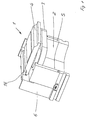
- Forming station 1 For reasons of clarity, however, only one half of Forming station 1 shown. In addition, missing in the presentation of Floor punch, which provided with the reference numeral 2 mold cavity limited to the bottom. In contrast, however, is shown the upper mold hollow boundary, which in this case from a Displacer 3 with the Verdrängerhalteplatte 4 consists.
- the left and right mold half 5 and not illustrated bottom punch existing tool package is in one Temperierrahmen 6 inserted, of which in the illustration 1 and Fig. 2, only one half is shown.
- the halves, however, are symmetrical to each other and constructed will be described with reference to FIGS. 5 and 6.
- Each tempering frame half 6 consists of a C-shaped base cut out 7, a rising from the base 7 side wall 8 and a at right angles from this side wall 8 extending rear wall 9, which serves as a rear abutment for the back wall of the Mold half 5 serves.
- In the rear wall 9 is a Centering and retaining bushing 10, in which when inserting the Mold kits on at the back wall of the respective ones Tool half 5 located centering pin engages.
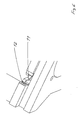
- a retaining bush 12 In front of the entrance to T-slot guide 11 is a retaining bush 12, in which - As can be seen from Figures 3 and 4 - a dome-shaped resiliently mounted pressure piece 13 can be latched, the one of the T-slot guide 11 complementary T-slot stone (pin 14) assigned is.
- the Endlagenbegrenzung in the insertion movement is done by Installation of the back wall of the mold halves 5 at the Rear system 9 of the tempering frame.
Landscapes
- Engineering & Computer Science (AREA)
- Mechanical Engineering (AREA)
- Manufacturing & Machinery (AREA)
- Moulds For Moulding Plastics Or The Like (AREA)
- Injection Moulding Of Plastics Or The Like (AREA)
Abstract
Description
Das auf dem Führungsblech liegende Werkzeugpaket wird dann mittels eines Roboters in die Einschuböffnung hineingeschoben, wonach nach Überwinden der Vorspannkraft des Druckstücks die Fixierung und Zentrierung des Werkzeugs im Temperierrahmen erfolgt.
- Fig. 1:
- Temperierrahmenhälfte mit eingeführter Werkzeughälfte und eingesetztem Verdränger,
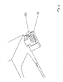
- Fig. 2:
- Vorrichtung gemäß Fig. 1 in anderer Perspektive,
- Fig. 3:
- Detail der Rastvorrichtung an der Werkzeugrahmenhälfte,
- Fig. 4:
- Darstellung gemäß Fig. 3 in anderer Perspektive,
- Fig. 5:
- Temperierrahmenhälfte in perspektivischer Darstellung,
- Fig. 6:
- Detailausschnitt aus Fig. 5 in etwas anderer Perspektive
Claims (11)
- Verfahren zum Formwerkzeugspannen in einer Formstation einer Spritzgießmaschine zur Herstellung von Schuhen und/oder Sohlen mit einem aus einem linken und rechten Werkzeugrahmen sowie einem Bodenstempel bestehenden Formwerkzeug, welches in einem zweiteiligen Temperierrahmen sowie auf einer den Bodenstempel tragenden Temperierplatte fixiert wird,
dadurch gekennzeichnet, dass die Werkzeugrahmenteile (5) in die jeweiligen Temperierrahmen eingeschoben werden, wobei die Werkzeugrahmenteile (5) mit den Temperierrahmenteilen (6) selbsttätig form- und/oder kraftschlüssig verrastet werden, und der Bodenstempel kraftschlüssig auf der Temperierplatte befestigt wird. - Verfahren nach Anspruch 1,
dadurch gekennzeichnet, dass zunächst das Formwerkzeug (5) aus linkem und rechtem Werkzeugrahmen und dem Bodenstempel zu einem Werkzeugpaket - eine einseitig offene Formkavität (2) bildend - zusammengestellt und dann über eine Führung in den geschlossenen Temperierrahmen (6) eingeschoben wird, wobei die Werkzeugrahmenteile (5) mit den Temperierrahmenteilen (6) selbsttätig form- und/oder kraftschlüssig verrastet werden, und der Bodenstempel kraftschlüssig auf der Temperierplatte befestigt wird. - Verfahren nach Anspruch 2,
dadurch gekennzeichnet, dass nach dem Einschieben des Werkzeugpakets und dem Verrasten desselben die Hälften des Temperierrahmens (6) auseinandergefahren werden, wonach in das Werkzeug (5) ein Verdränger (3) als abschließende Formkavitätsbegrenzung eingeführt wird, der beim Wiederzusammenfahren des Temperierrahmens (6) durch am Temperierrahmen vorgesehene Spannelemente (16) verriegelt wird. - Formstation einer Spritzgießmaschine zur Durchführung des Verfahrens nach Anspruch 1, 2 oder mit einem aus einem linken und rechten Werkzeugrahmen und einem Bodenstempel bestehenden Formwerkzeug, welches in einem zweiteiligen Temperierrahmen sowie auf einer den Bodenstempel tragenden Temperierplatte fixierbar ist,
dadurch gekennzeichnet, dass die Formwerkzeugteile (5) mittels Rastelementen (10,13,12) selbsttätig form- und kraftschlüssig am jeweiligen Temperierrahmenteil(6) festlegbar sind. - Formstation nach Anspruch 4,
dadurch gekennzeichnet, dass das Formwerkzeug (5) in zusammengebautem Zustand in den geschlossenen Temperierrahmen (6) einschiebbar bzw. auf die Temperierplatte aufschiebbar und mittels Rastelementen (10,13,12) selbsttätig form- und kraftschlüssig festlegbar ist. - Formstation nach Anspruch 4 oder 5,
dadurch gekennzeichnet, dass in der in Einschubrichtung hinteren Anlagefläche (9) jeder Temperierrahmenhälfte (6) eine Zentrier- und Haltebuchse (10) vorgesehen ist, in die ein an der hinteren Anlagefläche der jeweiligen Werkzeugrahmenhälfte (5) angeordneter Zentrierstift einrastbar ist und dass im Randbereich der Formwerkzeug-Einschuböffnung jeder Temperierrahmenhälfte (6) eine Führungsnut (11) für einen an der jeweiligen Werkzeugrahmenhälfte (5) vorgesehenen, zum Nutquerschnitt komplementärer Zapfen (14) angeordnet ist und sowohl an der Nut (11) als auch am Zapfen (14) miteinander zusammenwirkende, einander komplementäre Rastelemente (12,13) vorgesehen sind. - Formstation nach Anspruch 6,
dadurch gekennzeichnet, dass die Führungsnut (11) unterhalb der Einschuböffnung angeordnet ist und einen zur Einschuböffnung hin offenen Kanal bildet und der zugehörige Zapfen (14) nach unten vorstehend am Werkzeugrahmenteil (5) angeordnet ist. - Formstation nach Anspruch 7,
dadurch gekennzeichnet, dass der Querschnitt der Führungsnut (11) T-förmig ausgebildet ist, wobei der senkrechte T-Balken zur Einschuböffnung weist. - Formstation nach einem der Ansprüche 4bis 8,
dadurch gekennzeichnet, dass seitlich vor dem Nuteingang eine Haltebuchse (12) am Temperierrahmen (6) vorgesehen ist, in die ein seitlich vor dem Zapfen (14) angeordnetes federndes Druckstück (13) einrastbar ist. - Formstation nach Anspruch 9,
dadurch gekennzeichnet, dass die Vorspannkraft des Druckstücks (13) einstellbar ist. - Formstation nach einem der Ansprüche 4 bis 10,
dadurch gekennzeichnet, dass zur Zuführung des Werkzeugpakets in die Einschuböffnung des Temperierrahmens (6) ein Führungsblech vorgesehen ist, in dem Ausnehmungen für die an den Werkzeugrahmenhälften (5) vorgesehenen Zapfen (14) sowie für den Befestigungspilz des Bodenstempels vorgesehen sind, welche mit den Führungsnuten (11) sowie einer Aussparung für den Befestigungspilz des Bodenstempels im Temperierrahmen (6) fluchten.
Applications Claiming Priority (2)
| Application Number | Priority Date | Filing Date | Title |
|---|---|---|---|
| DE10142753 | 2001-08-31 | ||
| DE10142753A DE10142753B4 (de) | 2001-08-31 | 2001-08-31 | Verfahren zum Formwerkzeugspannen in einer Formstation einer Spritzgießmaschine, sowie Formstation |
Publications (2)
| Publication Number | Publication Date |
|---|---|
| EP1287963A1 true EP1287963A1 (de) | 2003-03-05 |
| EP1287963B1 EP1287963B1 (de) | 2009-04-08 |
Family
ID=7697299
Family Applications (1)
| Application Number | Title | Priority Date | Filing Date |
|---|---|---|---|
| EP02014290A Expired - Lifetime EP1287963B1 (de) | 2001-08-31 | 2002-06-27 | Verfahren zum Formwerkzeugspannen sowie Formstation einer Spritzgiessmaschine |
Country Status (10)
| Country | Link |
|---|---|
| EP (1) | EP1287963B1 (de) |
| KR (1) | KR100736475B1 (de) |
| CN (1) | CN1181960C (de) |
| AT (1) | ATE427823T1 (de) |
| DE (2) | DE10142753B4 (de) |
| DK (1) | DK1287963T3 (de) |
| ES (1) | ES2324982T3 (de) |
| MX (1) | MXPA02008130A (de) |
| PT (1) | PT1287963E (de) |
| TW (1) | TW575490B (de) |
Cited By (1)
| Publication number | Priority date | Publication date | Assignee | Title |
|---|---|---|---|---|
| CN102294786A (zh) * | 2011-08-06 | 2011-12-28 | 浙江任浪鞋材有限公司 | 鞋跟单钉天皮模架 |
Families Citing this family (2)
| Publication number | Priority date | Publication date | Assignee | Title |
|---|---|---|---|---|
| DE102005046138A1 (de) * | 2005-09-27 | 2007-03-29 | Uhlsport Gmbh | Sportschuh und Verfahren zu seiner Herstellung |
| CN101804686A (zh) * | 2010-03-17 | 2010-08-18 | 陈达金 | 二次一体成型鞋及制鞋模具和制造方法 |
Citations (7)
| Publication number | Priority date | Publication date | Assignee | Title |
|---|---|---|---|---|
| FR1498602A (fr) * | 1966-09-07 | 1967-10-20 | Perfectionnement aux dispositifs de moulage utilisés pour la fabrication de chaussures et articles similaires | |
| US3350748A (en) * | 1965-07-27 | 1967-11-07 | United Shoe Machinery Corp | Quick change mold assemblies |
| FR2581582A1 (fr) * | 1985-05-08 | 1986-11-14 | Kloeckner Ferromatik Desma | Dispositif pour le moulage direct de semelles sur des tiges de chaussures |
| EP0413149A2 (de) * | 1989-08-12 | 1991-02-20 | KlÀ¶ckner Desma GmbH | Schnellspannvorrichtung für Formenteile von Spritzgiessmaschinen |
| FR2714866A1 (fr) * | 1994-01-07 | 1995-07-13 | Rivabel | Ensemble de moulage pour chaussures. |
| FR2768029A1 (fr) * | 1997-09-11 | 1999-03-12 | Etabissements Jean Petit Et Ci | Machine et procede de fabrication d'articles chaussants tels que pantoufles et articles chaussants ainsi realises |
| DE19910190A1 (de) * | 1999-03-01 | 2000-09-07 | Kloeckner Desma Schuhmaschinen | Schnellspanneinrichtung |
-
2001
- 2001-08-31 DE DE10142753A patent/DE10142753B4/de not_active Expired - Fee Related
-
2002
- 2002-06-27 EP EP02014290A patent/EP1287963B1/de not_active Expired - Lifetime
- 2002-06-27 DK DK02014290T patent/DK1287963T3/da active
- 2002-06-27 DE DE50213425T patent/DE50213425D1/de not_active Expired - Lifetime
- 2002-06-27 ES ES02014290T patent/ES2324982T3/es not_active Expired - Lifetime
- 2002-06-27 AT AT02014290T patent/ATE427823T1/de not_active IP Right Cessation
- 2002-06-27 PT PT02014290T patent/PT1287963E/pt unknown
- 2002-07-03 TW TW91114722A patent/TW575490B/zh not_active IP Right Cessation
- 2002-08-14 KR KR1020020048065A patent/KR100736475B1/ko not_active IP Right Cessation
- 2002-08-21 MX MXPA02008130A patent/MXPA02008130A/es active IP Right Grant
- 2002-08-30 CN CNB021419892A patent/CN1181960C/zh not_active Expired - Fee Related
Patent Citations (7)
| Publication number | Priority date | Publication date | Assignee | Title |
|---|---|---|---|---|
| US3350748A (en) * | 1965-07-27 | 1967-11-07 | United Shoe Machinery Corp | Quick change mold assemblies |
| FR1498602A (fr) * | 1966-09-07 | 1967-10-20 | Perfectionnement aux dispositifs de moulage utilisés pour la fabrication de chaussures et articles similaires | |
| FR2581582A1 (fr) * | 1985-05-08 | 1986-11-14 | Kloeckner Ferromatik Desma | Dispositif pour le moulage direct de semelles sur des tiges de chaussures |
| EP0413149A2 (de) * | 1989-08-12 | 1991-02-20 | KlÀ¶ckner Desma GmbH | Schnellspannvorrichtung für Formenteile von Spritzgiessmaschinen |
| FR2714866A1 (fr) * | 1994-01-07 | 1995-07-13 | Rivabel | Ensemble de moulage pour chaussures. |
| FR2768029A1 (fr) * | 1997-09-11 | 1999-03-12 | Etabissements Jean Petit Et Ci | Machine et procede de fabrication d'articles chaussants tels que pantoufles et articles chaussants ainsi realises |
| DE19910190A1 (de) * | 1999-03-01 | 2000-09-07 | Kloeckner Desma Schuhmaschinen | Schnellspanneinrichtung |
Cited By (2)
| Publication number | Priority date | Publication date | Assignee | Title |
|---|---|---|---|---|
| CN102294786A (zh) * | 2011-08-06 | 2011-12-28 | 浙江任浪鞋材有限公司 | 鞋跟单钉天皮模架 |
| CN102294786B (zh) * | 2011-08-06 | 2013-07-17 | 浙江任浪鞋材有限公司 | 鞋跟单钉天皮模架 |
Also Published As
| Publication number | Publication date |
|---|---|
| ATE427823T1 (de) | 2009-04-15 |
| DE10142753A1 (de) | 2003-04-10 |
| CN1181960C (zh) | 2004-12-29 |
| ES2324982T3 (es) | 2009-08-21 |
| DE50213425D1 (de) | 2009-05-20 |
| DK1287963T3 (da) | 2009-07-27 |
| PT1287963E (pt) | 2009-07-13 |
| CN1406734A (zh) | 2003-04-02 |
| MXPA02008130A (es) | 2005-09-08 |
| EP1287963B1 (de) | 2009-04-08 |
| KR100736475B1 (ko) | 2007-07-06 |
| DE10142753B4 (de) | 2004-04-22 |
| TW575490B (en) | 2004-02-11 |
| KR20030019864A (ko) | 2003-03-07 |
Similar Documents
| Publication | Publication Date | Title |
|---|---|---|
| DE2732423C3 (de) | Vorrichtung zum Herstellen eines Hulsenteiles | |
| WO2018185129A1 (de) | Spritzgusswerkzeug und verfahren zur herstellung eines spritzgusserzeugnisses mit einem langen, dünnen kanal | |
| DE10217584B4 (de) | Spritzgießeinrichtung | |
| DE3742874A1 (de) | Verfahren und einrichtung zum sichern der rolladenstaebe eines rolladens gegen axiale gegenseitige verschiebung | |
| DE3612255A1 (de) | Werkzeug zum herstellen von stiefeln aus thermoplastischem material, wobei der stiefelschaft eine andere farbe hat als der schaftrand und die laufsohle, die die gleiche farbe aufweisen | |
| DE4142410C2 (de) | Vorrichtung zum Herstellen von flachen Kunststoff-Formstücken, beispielsweise Ausweiskarten durch Spritzgießen | |
| DE3516510A1 (de) | Vorrichtung zum direktansohlen an schuhschaefte | |
| EP1287963B1 (de) | Verfahren zum Formwerkzeugspannen sowie Formstation einer Spritzgiessmaschine | |
| DE2350810A1 (de) | Vorrichtung zur herstellung von behaeltern | |
| DE102006057241A1 (de) | Maschine zum Herstellen von gedrehten Bürsten | |
| DE19949851C2 (de) | Kunststoff-Spritzgießmaschine, Handlingsystem sowie Verfahren zum Überführen eines Gegenstandes | |
| DE102004036636A1 (de) | Verfahren, Vorrichtung und Anlage zur Wärmeformung und Umreifung von Behältern | |
| DE3440567A1 (de) | Sportschuh, insbesondere fussballschuh, mit einer gespritzten und an die brandsohle angeformten sohle und mit gespritzten nocken | |
| DE2121460C3 (de) | Vorrichtung zum Anformen von Sohlen | |
| DE19525000C1 (de) | Spritzgießwerkzeug zur Herstellung eines aus Kunststoff bestehenden Kastens | |
| DE2002361B2 (de) | Verfahren zur Herstellung eines Kamera-Suchergehäuses aus Kunststoff und Vorrichtung zur Durchführung des Verfahrens | |
| EP1623811B1 (de) | Spritzgusswerkzeug zur Herstellung von Kunststoffteilen, insbesondere derartiges Werkzeug zum Herstellen von zwei Kunststoffleisten verbindenden Spritzguss-Eckverbindungsteilen | |
| DE2451075A1 (de) | Verfahren zum spritzen von schuhsohlen und vorrichtung zu seiner durchfuehrung | |
| DE3001651A1 (de) | Einspritz-formmaschine | |
| DE10214466A1 (de) | Spritzgießmaschine | |
| DE2116125A1 (de) | Vorrichtung zur Herstellung einer Eckverbindung an Kunststoffrahmen-Hohlprofilen | |
| CH680700A5 (en) | Sliding clasp fastener teeth prodn. | |
| DE2911602C2 (de) | Vorrichtung zum Spannen des Schaftes auf den Leisten für Schuhwerk mit auswärts gewendetem Schaftrand | |
| EP0325948A2 (de) | Verfahren und Vorrichtung zum Anformen einer Sohle aus Kunststoff an einen aufgeleisteten, teilweise offenen Schaft | |
| DE19910190C2 (de) | Schnellspanneinrichtung |
Legal Events
| Date | Code | Title | Description |
|---|---|---|---|
| PUAI | Public reference made under article 153(3) epc to a published international application that has entered the european phase |
Free format text: ORIGINAL CODE: 0009012 |
|
| AK | Designated contracting states |
Kind code of ref document: A1 Designated state(s): AT BE CH CY DE DK ES FI FR GB GR IE IT LI LU MC NL PT SE TR |
|
| AX | Request for extension of the european patent |
Extension state: AL LT LV MK RO SI |
|
| 17P | Request for examination filed |
Effective date: 20030502 |
|
| AKX | Designation fees paid |
Designated state(s): AT BE CH CY DE DK ES FI FR GB GR IE IT LI LU MC NL PT SE TR |
|
| 17Q | First examination report despatched |
Effective date: 20060906 |
|
| GRAP | Despatch of communication of intention to grant a patent |
Free format text: ORIGINAL CODE: EPIDOSNIGR1 |
|
| GRAS | Grant fee paid |
Free format text: ORIGINAL CODE: EPIDOSNIGR3 |
|
| GRAA | (expected) grant |
Free format text: ORIGINAL CODE: 0009210 |
|
| AK | Designated contracting states |
Kind code of ref document: B1 Designated state(s): AT BE CH CY DE DK ES FI FR GB GR IE IT LI LU MC NL PT SE TR |
|
| REG | Reference to a national code |
Ref country code: GB Ref legal event code: FG4D Free format text: NOT ENGLISH |
|
| REG | Reference to a national code |
Ref country code: CH Ref legal event code: EP |
|
| REG | Reference to a national code |
Ref country code: IE Ref legal event code: FG4D |
|
| REF | Corresponds to: |
Ref document number: 50213425 Country of ref document: DE Date of ref document: 20090520 Kind code of ref document: P |
|
| REG | Reference to a national code |
Ref country code: PT Ref legal event code: SC4A Free format text: AVAILABILITY OF NATIONAL TRANSLATION Effective date: 20090703 |
|
| REG | Reference to a national code |
Ref country code: DK Ref legal event code: T3 |
|
| REG | Reference to a national code |
Ref country code: ES Ref legal event code: FG2A Ref document number: 2324982 Country of ref document: ES Kind code of ref document: T3 |
|
| REG | Reference to a national code |
Ref country code: IE Ref legal event code: FD4D |
|
| PG25 | Lapsed in a contracting state [announced via postgrant information from national office to epo] |
Ref country code: FI Free format text: LAPSE BECAUSE OF FAILURE TO SUBMIT A TRANSLATION OF THE DESCRIPTION OR TO PAY THE FEE WITHIN THE PRESCRIBED TIME-LIMIT Effective date: 20090408 |
|
| PG25 | Lapsed in a contracting state [announced via postgrant information from national office to epo] |
Ref country code: SE Free format text: LAPSE BECAUSE OF FAILURE TO SUBMIT A TRANSLATION OF THE DESCRIPTION OR TO PAY THE FEE WITHIN THE PRESCRIBED TIME-LIMIT Effective date: 20090708 |
|
| BERE | Be: lapsed |
Owner name: KLOCKNER DESMA SCHUHMASCHINEN G.M.B.H. Effective date: 20090630 |
|
| PG25 | Lapsed in a contracting state [announced via postgrant information from national office to epo] |
Ref country code: IE Free format text: LAPSE BECAUSE OF FAILURE TO SUBMIT A TRANSLATION OF THE DESCRIPTION OR TO PAY THE FEE WITHIN THE PRESCRIBED TIME-LIMIT Effective date: 20090408 Ref country code: MC Free format text: LAPSE BECAUSE OF NON-PAYMENT OF DUE FEES Effective date: 20090630 |
|
| REG | Reference to a national code |
Ref country code: CH Ref legal event code: PL |
|
| PLBE | No opposition filed within time limit |
Free format text: ORIGINAL CODE: 0009261 |
|
| STAA | Information on the status of an ep patent application or granted ep patent |
Free format text: STATUS: NO OPPOSITION FILED WITHIN TIME LIMIT |
|
| 26N | No opposition filed |
Effective date: 20100111 |
|
| GBPC | Gb: european patent ceased through non-payment of renewal fee |
Effective date: 20090708 |
|
| REG | Reference to a national code |
Ref country code: FR Ref legal event code: ST Effective date: 20100226 |
|
| PG25 | Lapsed in a contracting state [announced via postgrant information from national office to epo] |
Ref country code: LI Free format text: LAPSE BECAUSE OF NON-PAYMENT OF DUE FEES Effective date: 20090630 Ref country code: CH Free format text: LAPSE BECAUSE OF NON-PAYMENT OF DUE FEES Effective date: 20090630 Ref country code: FR Free format text: LAPSE BECAUSE OF NON-PAYMENT OF DUE FEES Effective date: 20090630 |
|
| PG25 | Lapsed in a contracting state [announced via postgrant information from national office to epo] |
Ref country code: GB Free format text: LAPSE BECAUSE OF NON-PAYMENT OF DUE FEES Effective date: 20090708 |
|
| PG25 | Lapsed in a contracting state [announced via postgrant information from national office to epo] |
Ref country code: BE Free format text: LAPSE BECAUSE OF NON-PAYMENT OF DUE FEES Effective date: 20090630 |
|
| PG25 | Lapsed in a contracting state [announced via postgrant information from national office to epo] |
Ref country code: AT Free format text: LAPSE BECAUSE OF NON-PAYMENT OF DUE FEES Effective date: 20090627 |
|
| PG25 | Lapsed in a contracting state [announced via postgrant information from national office to epo] |
Ref country code: GR Free format text: LAPSE BECAUSE OF FAILURE TO SUBMIT A TRANSLATION OF THE DESCRIPTION OR TO PAY THE FEE WITHIN THE PRESCRIBED TIME-LIMIT Effective date: 20090709 |
|
| PG25 | Lapsed in a contracting state [announced via postgrant information from national office to epo] |
Ref country code: LU Free format text: LAPSE BECAUSE OF NON-PAYMENT OF DUE FEES Effective date: 20090627 |
|
| PGFP | Annual fee paid to national office [announced via postgrant information from national office to epo] |
Ref country code: TR Payment date: 20110620 Year of fee payment: 10 |
|
| PG25 | Lapsed in a contracting state [announced via postgrant information from national office to epo] |
Ref country code: CY Free format text: LAPSE BECAUSE OF FAILURE TO SUBMIT A TRANSLATION OF THE DESCRIPTION OR TO PAY THE FEE WITHIN THE PRESCRIBED TIME-LIMIT Effective date: 20090408 |
|
| PG25 | Lapsed in a contracting state [announced via postgrant information from national office to epo] |
Ref country code: TR Free format text: LAPSE BECAUSE OF NON-PAYMENT OF DUE FEES Effective date: 20120627 |
|
| PGFP | Annual fee paid to national office [announced via postgrant information from national office to epo] |
Ref country code: ES Payment date: 20150626 Year of fee payment: 14 Ref country code: PT Payment date: 20150615 Year of fee payment: 14 Ref country code: DE Payment date: 20150619 Year of fee payment: 14 Ref country code: DK Payment date: 20150618 Year of fee payment: 14 |
|
| PGFP | Annual fee paid to national office [announced via postgrant information from national office to epo] |
Ref country code: NL Payment date: 20150618 Year of fee payment: 14 Ref country code: IT Payment date: 20150622 Year of fee payment: 14 |
|
| REG | Reference to a national code |
Ref country code: DE Ref legal event code: R119 Ref document number: 50213425 Country of ref document: DE |
|
| REG | Reference to a national code |
Ref country code: DK Ref legal event code: EBP Effective date: 20160630 |
|
| REG | Reference to a national code |
Ref country code: NL Ref legal event code: MM Effective date: 20160701 |
|
| PG25 | Lapsed in a contracting state [announced via postgrant information from national office to epo] |
Ref country code: PT Free format text: LAPSE BECAUSE OF NON-PAYMENT OF DUE FEES Effective date: 20161227 |
|
| PG25 | Lapsed in a contracting state [announced via postgrant information from national office to epo] |
Ref country code: DE Free format text: LAPSE BECAUSE OF NON-PAYMENT OF DUE FEES Effective date: 20170103 |
|
| PG25 | Lapsed in a contracting state [announced via postgrant information from national office to epo] |
Ref country code: NL Free format text: LAPSE BECAUSE OF NON-PAYMENT OF DUE FEES Effective date: 20160701 |
|
| PG25 | Lapsed in a contracting state [announced via postgrant information from national office to epo] |
Ref country code: IT Free format text: LAPSE BECAUSE OF NON-PAYMENT OF DUE FEES Effective date: 20160627 |
|
| PG25 | Lapsed in a contracting state [announced via postgrant information from national office to epo] |
Ref country code: DK Free format text: LAPSE BECAUSE OF NON-PAYMENT OF DUE FEES Effective date: 20160630 |
|
| PG25 | Lapsed in a contracting state [announced via postgrant information from national office to epo] |
Ref country code: ES Free format text: LAPSE BECAUSE OF NON-PAYMENT OF DUE FEES Effective date: 20160628 |
|
| REG | Reference to a national code |
Ref country code: ES Ref legal event code: FD2A Effective date: 20181130 |