EP1287263B1 - Mutter - Google Patents
Mutter Download PDFInfo
- Publication number
- EP1287263B1 EP1287263B1 EP01944929A EP01944929A EP1287263B1 EP 1287263 B1 EP1287263 B1 EP 1287263B1 EP 01944929 A EP01944929 A EP 01944929A EP 01944929 A EP01944929 A EP 01944929A EP 1287263 B1 EP1287263 B1 EP 1287263B1
- Authority
- EP
- European Patent Office
- Prior art keywords
- nut
- jaws
- outer body
- section
- guide means
- Prior art date
- Legal status (The legal status is an assumption and is not a legal conclusion. Google has not performed a legal analysis and makes no representation as to the accuracy of the status listed.)
- Expired - Lifetime
Links
- 210000001331 nose Anatomy 0.000 claims description 8
- 230000002093 peripheral effect Effects 0.000 claims description 2
- 210000002414 leg Anatomy 0.000 description 12
- 230000000903 blocking effect Effects 0.000 description 2
- 239000000463 material Substances 0.000 description 2
- 238000013459 approach Methods 0.000 description 1
- 239000002131 composite material Substances 0.000 description 1
- 230000007797 corrosion Effects 0.000 description 1
- 238000005260 corrosion Methods 0.000 description 1
- 238000002788 crimping Methods 0.000 description 1
- 238000006073 displacement reaction Methods 0.000 description 1
- 238000003780 insertion Methods 0.000 description 1
- 230000037431 insertion Effects 0.000 description 1
- 238000012986 modification Methods 0.000 description 1
- 230000004048 modification Effects 0.000 description 1
- 229920001296 polysiloxane Polymers 0.000 description 1
- 230000007704 transition Effects 0.000 description 1
- 210000000689 upper leg Anatomy 0.000 description 1
Images


Classifications
-
- F—MECHANICAL ENGINEERING; LIGHTING; HEATING; WEAPONS; BLASTING
- F16—ENGINEERING ELEMENTS AND UNITS; GENERAL MEASURES FOR PRODUCING AND MAINTAINING EFFECTIVE FUNCTIONING OF MACHINES OR INSTALLATIONS; THERMAL INSULATION IN GENERAL
- F16B—DEVICES FOR FASTENING OR SECURING CONSTRUCTIONAL ELEMENTS OR MACHINE PARTS TOGETHER, e.g. NAILS, BOLTS, CIRCLIPS, CLAMPS, CLIPS OR WEDGES; JOINTS OR JOINTING
- F16B37/00—Nuts or like thread-engaging members
- F16B37/08—Quickly-detachable or mountable nuts, e.g. consisting of two or more parts; Nuts movable along the bolt after tilting the nut
- F16B37/0807—Nuts engaged from the end of the bolt, e.g. axially slidable nuts
- F16B37/0864—Nuts engaged from the end of the bolt, e.g. axially slidable nuts with the threaded portions of the nut engaging the thread of the bolt by pressing or rotating an external retaining member such as a cap, a nut, a ring or a sleeve
Definitions
- Such a nut is known from DE 40 24 784 A1. She is there as “Quick assembly nut”. In this known nut is the axial Through opening of the outer body, which is referred to there as an "outer member", a hexagonal internal bore with a foremost area in the axial direction has constant internal dimensions, and a subsequent conical Range approaching in the release direction of the nut of the axle.
- the jaws of this known mother who referred to there as “inner nut segments” are each having a front portion, which is the respective internal thread segment carries, and an integrally adjoining rear section.
- This rear portion is shaped like the front portion, but is slightly angled outwards relative to this and has instead of the internal thread segment a threadless recess on whose inner dimensions larger than the female thread segment.
- the jaws are at the transition point between the front sections and the pivotally mounted behind each other back sections. If now the outer body relative to the inner body forward, so pushed in the tightening of the mother is, then the jaws are pivoted to each other such that the Front sections closed, that is closed, so that the inner nut segments in the front sections form the internal thread of the nut. In this closed state of the mother sits the outer body on the front sections, while the back sections are unfolded.
- a similar nut is known from FR 2 640 336 A1. Also with this mother The jaws are pivotally mounted together, but wear in this nut the rear portions of the female thread segments, while the front portions have the threadless recess. Therefore, this mother is closed, when the outer body is displaced relative to the inner body in the release direction is opened and opened when the outer body relative to the réelleköroper in Pulling direction is pushed.
- each inner thread segment is relative to the External thread of the threaded rod turned during the folding movement about an axis which is perpendicular to the longitudinal axis, so that the threads slightly together snag.
- a nut which has an inner body, which is divided into at least two jaws, when moving the outer body be compressed relative to the inner body in the release direction of the mother Is this mother tightened and the outer body is relative to the inner body moved in the release direction, so the jaws tighten due to the orientation of the conical inner surface of the outer body together.
- This object is achieved in that the jaws when moving the outer body moved apart relative to the inner body in the release direction of the mother and the composite jaws at least a first to the longitudinal axis parallel section and at least a second in the tightening of the nut have from the longitudinal axis removing portion.
- Such an embodiment of the invention makes it possible, on the one hand, the mother to be able to pull off quickly from a threaded shaft, without this around its longitudinal axis to have to turn.
- a displacement of the outer body relative to the inner body For this purpose, move the jaws radially outward.
- over the parallel sections only radially outward forces over the Bakken transferred to the outer body, so no axial force on the outer body acts, which would act in the release direction of the mother.
- the object is further characterized solved that the jaws when the outer body relative to the inner body in Release direction is shifted, moved radially outward and, if the Outer body is moved relative to the inner body in the tightening direction, radially inwardly be moved.
- the second guide means comprise grooves which in The sides of the jaws run and in the direction of attraction of the axis remove, and that the first guide means comprise lugs that from the through hole to jump up and run in the grooves.
- the jaws become shifted radially inwardly when the outer body in the tightening direction on the inner body is pushed, and moved radially outward when the outer body withdrawn in the release direction of the inner body.
- each jaw an outer wedge surface, which is away from the axis in the tightening direction, and at the through-hole to each Jaw an inner wedge surface is provided, which corresponds to the associated outer wedge surface in the tightening direction away from the axis.
- the jaws biased radially outward are.
- a locking pin transversely displaceable to the axis is guided by the outer body and in its locked position with his inner end to a latching surface, the at least one jaw transverse to the axis in Attention is provided tightening, rests and in its release position with its inner end past this locking surface and together with the outer body can be moved in the release direction.
- the outer end of the locking pin in the Locking position protrudes from the outer peripheral surface of the outer body and the inner end of the locking pin and the locking surface are formed so that the Locking pin brought by pushing from the locked position to the release position can be.
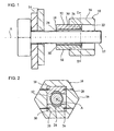
- FIGS. 1-4 a nut 10 is shown in a first embodiment.
- the nut 10 is in an open state, so that they without threaded engagement on the threaded shaft 12 of a screw passing through two objects 14 to be screwed are guided, in FIG. 1 to the left, that is pushed in its tightening direction and from this to the right, that is in their release direction can be deducted.
- the nut 10 has an outer body 16 and two jaws 18, 20.
- the outer body 16 has an axial passage opening 22 in which the jaws 18, 20 in axially slidably received, as explained in more detail below becomes.
- the passage opening 22 here has a rectangular cross-section and runs coaxially to the longitudinal axis A of the nut 10.
- the jaws 18, 20 are cuboidal here Blocks whose length corresponds to the length of the outer body 16 and whose Width is slightly smaller than the width of the through hole 22, as in the FIG. 2 is easy to see, so that they are non-rotatably seated in the passage opening 22.
- Each jaw 18, 20 has on its radially inner surface, ie on that surface, to the threaded shaft 12, a female thread segment 24, the fitting is formed to the external thread of the threaded shaft 12. Consequently, the in the FIG. 1 and 2 upper jaw 18 her female thread segment 24 on its underside, while the lower jaw 20 carries its female thread segment 24 on its upper side.
- the two jaws 18, 20 are symmetrical distributed around the longitudinal axis A and thus also around the threaded shaft 12, the means they are at an angular distance of 180 ° to each other.
- This arrangement applies correspondingly also for other embodiments (not shown) of the nut 10, where more than two jaws are provided: in the case of three jaws are this then preferably at an angular distance of 120 ° to each other about the longitudinal axis A. arranged around.
- first guide means are provided on the outer body 16, which here comprise four lugs 26 projecting from the passage opening 22.
- the noses 26 are here through the inner end of Pins formed, which are inserted from the outside into through holes 28 in the outer body 16 were.
- each groove 30 includes, in each of which one of the lugs 26 runs. Every cheek 18, 20 has its in FIG. 2 left side surface of a groove 30 and in their right Side surface on a symmetrical to this other groove 30.
- grooves are straight here, they can also be curved in the axial direction be.
- FIGS. 1 and 2 the operation of the nut 10 described.
- the nut 10 is shown in the open state, in the jaws 18, 20 are so far apart that their internal thread segments 24 are not in engagement with the external thread of the threaded shaft 12.
- the nut 10 can therefore in this open state to the right in the FIG. 1, ie in the release direction, are quickly removed from the threaded shaft 12, without having to be rotated about its longitudinal axis A, as in a conventional one-piece mother is the case.
- the mother 10 can of course also after left, that is in the tightening direction, quickly pushed onto the threaded shaft 12 without having to be turned.
- the outer body 16 is relative to the jaws 18, 20 in the release direction until the stop of the lugs 26 at the right end of the grooves 30 shifted so that the jaws 18, 20 only to about half in the through hole 22 stuck. Since each groove 30 with its right end closer to the Longitudinal axis A is as with their remaining course, the jaws 18, 20 so far moved apart, that their female thread segments 24 are not engaged with the Threaded shaft 12 stand.
- the height of the jaws 18, 20 is chosen so that they with their radially outer surface 32, in the upper jaw 18 whose top and at the lower jaw 20th whose bottom is, in this open state, the nut 10 at the top or lower surface of the through hole 22, it is prevented around the noses 30 tilt down and then that the lower left edge of the upper Jaw 18 and the right upper edge of the lower jaw 20 on the threaded shaft 12 abut.
- the outer body 16 is not unintentionally relative to the inner body in the release direction away slips, which can occur, for example, when the screw from nut 10 and threaded shaft 12 vibration is exposed, the grooves can 30 have at their left end a portion which is parallel to the longitudinal axis A runs and only after this parallel section in the release direction, that is, to the right of the longitudinal axis A approaches. This is especially good in FIG. 5 to recognize.
- the outer body 16 are moved so far relative to these in the release direction until the noses 26 has arrived at the right end of this parallel portion of the grooves 30.
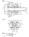
- FIGS. 6 and 7 two jaws 18, 20 are shown in a second embodiment.
- a parallel to this second groove 30 ' is provided to the left of each groove 30 .
- the outer body 16 of FIG. 1 to 4 (not shown) to the left of each nose 26 (indicated as a dotted line) also a second Nose 26 '(indicated as a dotted line), in the associated second groove 30 'is running. This causes the jaws 18, 20 as parallel to Longitudinal axis A are held.
- Means which prevent the jaws 18, 20 are axially displaced relative to each other when the outer body is pushed onto or removed from them.
- Such Means are also suitable for all other embodiments of the jaws.
- These Means here include, for example, two guide rods 110, which on the in FIG. 6 right end of the jaws 18, 20 in FIG. 7 left and right next to the longitudinal axis A are arranged and each displaceable in two opposite guide holes 112 sit in the jaws 18, 20.
- the jaws 18, 20 can therefore for opening and closing as desired relative to each other radially, but not axially be moved.
- the means may also have fewer or more than two guide rods 110 include.
- the jaws 18, 20 by two coil springs 114 radially biased outwardly, each surrounded by a guide rod 110 and to support the underside of the upper jaw 18 and at the top of the lower jaw 20. As a result, the opening of the jaws 18, 20 during removal of the outer body 16 supported.
- FIGS. 1-7 illustrated form of the jaws 18, 20th
- these can also be shaped so that they are closed form a complete internal thread, as in the third embodiment of the Baking 18, 20 according to FIG. 8 is shown.
- FIGS. 9 and 10 the nut 10 is shown in a second embodiment. in the Difference to the first embodiment of FIG. 1 to 5 are here in addition to the first and second guide means 26, 30 corresponding wedge surfaces 34, 36 provided.
- an inner wedge surface 34 is provided, the is formed by the passage opening 22 and in the tightening of the Longitudinal axis A removed.
- a first inner wedge surface 34 is at the bottom, to upper jaw 18 facing top of the through hole 22 is formed, and a second inner wedge surface 34 is symmetrical thereto at the top, to the bottom Jaw 20 facing bottom of the through hole 22 is formed.
- an outer wedge surface 36 is provided on each jaw 18, 20, the formed corresponding to the respective opposite inner wedge surface 34 is and thus removed in the tightening of the longitudinal axis A.
- a first outer wedge surface 36 is formed at the top of the upper jaw 18, and a second outer wedge surface 36 is symmetrical thereto at the bottom of the lower Jaw 20 is formed.
- the corresponding inner and outer wedge surfaces 34, 36 are designed such that that in the closed state of the nut 10 they match each other exactly, as shown in FIG. 9 is clearly visible, and their inclination relative to the longitudinal axis A is chosen in view of the inclination of the grooves 30 such that they when moving the outer body 16 relative to the inner body 18, 20 for opening and closing the nut 10 can be moved past each other. In the closed State of the nut 10 is therefore a frictional engagement between the inner and outer wedge surfaces 34, 36, so that the outer body 16 on the inner body 18, 20 is held.
- the nut 10 is shown in a third embodiment, which a modification of the second embodiment of FIG. 9 and 10 represents.
- the wedge surfaces 34, 36 divided into five sections, namely in three to the longitudinal axis A.
- parallel sections 120 and into two inclined sections 122 which are in the tightening direction from the longitudinal axis A and between the three parallel sections 120 lie.
- the Grooves 30 are correspondingly parallel to the central parallel section 120 and the right oblique portion 122 adjoining on the right.
- wedge surfaces 34, 36 are planar here, they can also be curved as needed, in the axial direction and / or in the circumferential direction.
- FIGS. 11 and 12 is a radially outwardly projecting flange 124 on left outer edge of the jaws 18, 20 provided such that when closed Nut 10 between its right flank and the left end faces of the outer body 16 a gap is formed.
- the blade a screwdriver set and rotated to pry the nut 10, if the outer body 16 should sit so firmly on the inner body 18, 20 that he can not be pulled off with his fingers.
- This flange 124 is also suitable for all other embodiments of the nut 10.
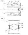
- the aforementioned unintentional slipping of the outer body 16 relative to Inner body 18, 20 in the release direction can also by the following measures prevented or at least impeded, which in the FIG. 13 to 16 shown are.
- a Clamping 38 may be mounted, of the corresponding wedge surface 34, 36th protrudes and made of a deformable material, such as rubber or silicone consists.
- a deformable material such as rubber or silicone consists.
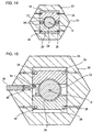
- FIG. 14 in which the nut 10 is shown in a fifth embodiment can also clamp body 38 on the upper jaw 18 and / or the lower Jaw 20 may be mounted in the closed state of the nut 10 between These jaws 18, 20 are clamped.
- the jaws 18, 20 are radial pressed outwards, so that in the case of the second embodiment of FIG. 9 and 10 and the third embodiment of FIG. 11 and 12 the friction between the inner and outer wedge surfaces 34, 36 and in the case of the first embodiment of the FIG. 1 to 4, the friction between the lugs 26 and the radially outer surfaces the grooves 30 is increased.
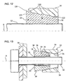
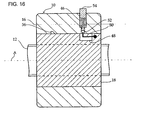
- FIGS. 15 and 16 the nut 10 of FIG. 4 is shown with a locking device. prevents the outer body 16 unintentionally when the nut 10 is closed relative to the inner body 18, 20 can be moved in the release direction.
- the locking device in a first embodiment according to FIG. 15 has a Locking pin 40, the transversely to the longitudinal axis A displaceable in a through hole is guided by the outer body 16 and from the passage opening 22nd protruding inwards with its inner end. Also, on the upper cheek 18 a locking surface 42 is provided, which is transverse to the longitudinal axis A in the tightening direction has. This locking surface 42 is here part of the left edge of the underside of the upper Jaw 18 downwardly projecting protrusion, which is above the top of the Locking pin 40 ends. The inner end of the locking pin 40 carries an upwardly angled Extension 44, which in the locked position of the locking pin 40 on the locking surface 42 is present. Now, if the locking pin 40 from the in FIG.
- the locking pin 40 is radially outwardly by a coil spring 46, that is in biased the blocking position, the thinner middle portion of the locking pin 40th surrounds and sits together with the locking pin 40 in the through hole.
- the Coil spring 46 is supported with its radially inner end to a shoulder of in a through bore and with its radially outer end on a shoulder of the Locking pin 40 from, as shown in FIG. 15 is clearly visible.
- the locking device is shown in a second embodiment.
- This second embodiment has the upper jaw 18 at the right end of its in FIG. 16 upwardly facing side surface on a recess 48, the one L-shaped spring plate 50 receives.
- the axial leg of this spring plate 50 is in attached to the right wall of the recess 48, and the outwardly directed radial leg the spring plate 50 jumps in the relaxed state of the spring plate 50th from the side surface of the jaw 28.
- closed State of the nut 10 projects the free end of this radial leg up into a through hole 52 in the outer body 16. This will be in this Locking position prevents the outer body 16 relative to the jaw 18 in the release direction, that is, to the right in FIG. 16 can be moved.
- This left edge of the through hole 52 thus has the same function as the locking surface 42 of the first Embodiment of the locking device.
- a release pin 54 is arranged, which like the locking pin 40 of FIG. 15 is biased radially outwardly by a coil spring 46 and with his outer end of the outer body 16 protrudes. Now, if the release pin 54 radially is pressed inwards, then pushes its inner end of the radial leg of the Spring plate 50 out of the through hole 52, wherein the axial leg is bent radially inwardly resiliently. Once the radial thigh is no longer in the Through hole 52 protrudes into the outer body 16 ver in the release direction be pushed.
- a blind hole 56 provided, in which engages the radial leg when the outer body 16th has been moved so far in the release direction that the internal thread segments 24 no longer be in engagement with the external thread of the threaded shaft 12. If the nut 10 in this open state in the tightening on the threaded shaft 12 is pushed, then prevents the locked in the blind hole 56 radial leg, that the outer body 10 is pushed onto the inner body 18, 20 when an internal thread segment 24 unintentionally on the threaded shaft 12th should get stuck.
- the release pin 54 also be omitted.
- Radial leg in the release position to bring, then, as before described at the blind hole 54, the left wall of the through hole 52 after be tilted lower left (not shown).
- the inclined at the Wall adjacent radial legs deflected radially inward until it does not more protrudes into the through hole 52 and the outer body 16 further unhindered relative to the inner body 18, 20 can be deducted.
- Each locking device of FIG. 15 and 16 is not only for nuts 10 with radially displaceable Baking 18, 20, as they are the subject of this invention, suitable but also for the known nuts with swivel jaws, as for example in DE 40 24 784 A1 and FR 2 640 336 A1 are described. This also applies to the clamping body 38 of FIG. 13 and 14.
- Both the locking pin 40 in FIG. 15 and the release pin 54 in FIG. 16 stand in its locking position with its outer end of the outer body 16 before, so that the user can press in with a finger to release. But an unintentional Preventing these outer ends in the Locking position are sunk in the corresponding through hole.
- a tool such as a pair of pliers, with a in the Through hole matching tooth required with the locking pin 40 respectively Release pin 54 can be pressed.
- the nut 10 is shown in a sixth embodiment.
- the jaws 18, 20 at its right end in the connection on her female thread segment 24 a threadless recess 58 on, in a bent insert 60 of deformable material, such as plastic sitting.
- a threadless recess 58 on, in a bent insert 60 of deformable material, such as plastic sitting.
- the nut 10 is shown in a seventh embodiment.
- These Nut 10 is intended for use on crimping tubes 60 having at their ends a Bear beading edge 64.
- this seventh embodiment is similar to the sixth embodiment at the right end of the jaws 18, 20 a recess 58 provided, in the closed state of the nut 10 of the flanged edge 64th fits into it.
- the jaws 10, 20 In the illustrated open state of the nut 10, the jaws 10, 20 so far apart that the beading 64 to the right in FIG. 18 can be pulled out of the recess 58. This is for example then required when seated on the flare 62 nut 10 are replaced got to.
Landscapes
- Engineering & Computer Science (AREA)
- General Engineering & Computer Science (AREA)
- Mechanical Engineering (AREA)
- Transmission Devices (AREA)
- Dowels (AREA)
- Mutual Connection Of Rods And Tubes (AREA)
- Materials For Medical Uses (AREA)
- Gripping Jigs, Holding Jigs, And Positioning Jigs (AREA)
- Valve Device For Special Equipments (AREA)
- Clamps And Clips (AREA)
- Saccharide Compounds (AREA)
Priority Applications (1)
| Application Number | Priority Date | Filing Date | Title |
|---|---|---|---|
| SI200130490T SI1287263T1 (sl) | 2000-05-16 | 2001-05-16 | Matica |
Applications Claiming Priority (3)
| Application Number | Priority Date | Filing Date | Title |
|---|---|---|---|
| DE10023675 | 2000-05-16 | ||
| DE10023675A DE10023675C2 (de) | 2000-05-16 | 2000-05-16 | Mutter |
| PCT/DE2001/001838 WO2001088390A1 (de) | 2000-05-16 | 2001-05-16 | Mutter |
Publications (2)
| Publication Number | Publication Date |
|---|---|
| EP1287263A1 EP1287263A1 (de) | 2003-03-05 |
| EP1287263B1 true EP1287263B1 (de) | 2005-11-09 |
Family
ID=7642060
Family Applications (1)
| Application Number | Title | Priority Date | Filing Date |
|---|---|---|---|
| EP01944929A Expired - Lifetime EP1287263B1 (de) | 2000-05-16 | 2001-05-16 | Mutter |
Country Status (16)
| Country | Link |
|---|---|
| US (1) | US7331745B2 (cg-RX-API-DMAC7.html) |
| EP (1) | EP1287263B1 (cg-RX-API-DMAC7.html) |
| JP (1) | JP2003533649A (cg-RX-API-DMAC7.html) |
| KR (1) | KR100896540B1 (cg-RX-API-DMAC7.html) |
| CN (1) | CN1207497C (cg-RX-API-DMAC7.html) |
| AT (1) | ATE309479T1 (cg-RX-API-DMAC7.html) |
| AU (1) | AU2001267306A1 (cg-RX-API-DMAC7.html) |
| BR (1) | BR0110834B1 (cg-RX-API-DMAC7.html) |
| CA (1) | CA2409017C (cg-RX-API-DMAC7.html) |
| DE (2) | DE10023675C2 (cg-RX-API-DMAC7.html) |
| DK (1) | DK1287263T3 (cg-RX-API-DMAC7.html) |
| EA (1) | EA004360B1 (cg-RX-API-DMAC7.html) |
| ES (1) | ES2252246T3 (cg-RX-API-DMAC7.html) |
| MX (1) | MXPA02011067A (cg-RX-API-DMAC7.html) |
| WO (1) | WO2001088390A1 (cg-RX-API-DMAC7.html) |
| ZA (1) | ZA200209140B (cg-RX-API-DMAC7.html) |
Cited By (1)
| Publication number | Priority date | Publication date | Assignee | Title |
|---|---|---|---|---|
| DE102017129644A1 (de) | 2017-08-22 | 2019-02-28 | DEHN + SÖHNE GmbH + Co. KG. | Schnellverschraubung, insbesondere zum Verbinden von mehrteiligen Baugruppen |
Families Citing this family (34)
| Publication number | Priority date | Publication date | Assignee | Title |
|---|---|---|---|---|
| DE10049092A1 (de) | 2000-09-27 | 2002-06-20 | Arno Giehl | Gesicherte Schraubenverbindung |
| GB0122486D0 (en) * | 2001-09-18 | 2001-11-07 | More Nicholas | Quick reaction nut |
| US6974291B2 (en) * | 2004-04-26 | 2005-12-13 | Feiyu Li | Quick coupling nut |
| DE102005046362A1 (de) * | 2005-09-28 | 2007-04-05 | Airbus Deutschland Gmbh | Klemmstück und Haltevorrichtung mit einem derartigen Klemmstück |
| FR2902473B1 (fr) * | 2006-06-15 | 2009-11-20 | Peugeot Citroen Automobiles Sa | Dispositif formant ecrou a montage rapide |
| US8540471B2 (en) * | 2006-07-05 | 2013-09-24 | Visenut Llc | Quick attaching and detaching nut |
| US20080008556A1 (en) * | 2006-07-05 | 2008-01-10 | Steven Dvorak | Quick Attaching and Detaching Nut |
| US8998155B2 (en) | 2008-10-30 | 2015-04-07 | Erico International Corporation | Quick threaded rod locking devices and method |
| DE102009039822A1 (de) * | 2009-09-02 | 2011-03-03 | Westfalia-Automotive Gmbh | Befestigungseinrichtung mit einer Spannmutteranordnung |
| DE102010016758B4 (de) * | 2010-05-03 | 2019-05-02 | Jörg Hohmann | Segmentierte Mutter für Verschraubungen |
| CN105579717A (zh) * | 2013-05-03 | 2016-05-11 | 爱瑞柯国际公司 | 快速螺杆锁紧装置及方法 |
| US9394706B2 (en) | 2013-10-08 | 2016-07-19 | Simpson Strong-Tie Company, Inc. | Concrete anchor |
| US9163655B2 (en) | 2014-01-14 | 2015-10-20 | Kaoru Taneichi | Thrust nut |
| CN104653581A (zh) * | 2015-03-20 | 2015-05-27 | 河海大学常州校区 | 一种组合式螺母 |
| CN106848930A (zh) * | 2016-01-15 | 2017-06-13 | 赵牧青 | 高压电力架线金具 |
| CN107046196A (zh) * | 2016-01-15 | 2017-08-15 | 赵牧青 | 电力架线金具 |
| CN108105147B (zh) * | 2016-01-25 | 2020-12-22 | 朱保生 | 采用控制系统的泵停车密封装置、工作方法 |
| ES2574992B1 (es) * | 2016-04-01 | 2017-01-20 | Schneider Electric España, S.A. | Dispositivo de bloqueo para soportes de conductos en suspensión |
| US10378257B2 (en) * | 2017-07-26 | 2019-08-13 | Fca Us Llc | Nut for threaded hinge pin |
| WO2019026253A1 (ja) * | 2017-08-03 | 2019-02-07 | 種市 薫 | ナット |
| CN108321688A (zh) * | 2017-12-29 | 2018-07-24 | 安徽乾轩信息科技有限公司 | 一种具有内置电力设备调节机构的低压配电柜 |
| CN108953350B (zh) * | 2018-07-31 | 2024-01-05 | 中山市美图塑料工业有限公司 | 一种能快速装拆的螺母及包含其的螺纹紧固组件 |
| CN108799310A (zh) * | 2018-08-27 | 2018-11-13 | 安徽西马新能源技术有限公司 | 一种汽车安装紧固组件 |
| CA3044632A1 (en) * | 2019-05-29 | 2020-11-29 | Gordian Enterprises Inc. | Split nut |
| CN112267780B (zh) * | 2020-10-13 | 2021-04-30 | 力野精密工业(深圳)有限公司 | 一种汽车门铰链 |
| CA3137418A1 (en) * | 2020-11-05 | 2022-05-05 | Eaton Intelligent Power Limited | Structural fastener including coupler for threaded rod |
| CA3150565A1 (en) * | 2021-03-03 | 2022-09-03 | Eaton Intelligent Power Limited | Structural fastener including coupler for threaded rod |
| US20220362952A1 (en) * | 2021-05-17 | 2022-11-17 | Big Country Concepts, LLC | Knife Enclosure |
| DE102022108601A1 (de) * | 2021-05-25 | 2022-12-01 | Illinois Tool Works Inc. | Vorrichtung zum Befestigen eines Bauteils an einem Trägerbauteil |
| EP4443011A1 (de) | 2023-03-15 | 2024-10-09 | Arno Giehl | Mutter |
| DE202023101283U1 (de) | 2023-03-15 | 2023-03-22 | Arno Giehl | Mutter |
| WO2024188805A1 (de) | 2023-03-15 | 2024-09-19 | Arno Giehl | Mutter |
| DE202023101439U1 (de) | 2023-03-22 | 2023-03-29 | Arno Giehl | Mutter |
| US20250257788A1 (en) * | 2024-02-14 | 2025-08-14 | Theodore James Thompson | Custom fastened locking stopping covered wire rope clip system |
Family Cites Families (19)
| Publication number | Priority date | Publication date | Assignee | Title |
|---|---|---|---|---|
| US3312264A (en) * | 1965-06-21 | 1967-04-04 | Dresdner Alexander | Speed-lock-nut |
| US3352341A (en) * | 1965-10-20 | 1967-11-14 | Eva N Schertz | Fast-action nut assembly |
| US4378187A (en) * | 1979-09-24 | 1983-03-29 | Fullerton Robert L | Quick-acting nut assembly |
| JPS58121310A (ja) * | 1981-12-08 | 1983-07-19 | 大洋製器工業株式会社 | タ−ンバツクル |
| FR2640336B1 (fr) * | 1988-12-12 | 1991-03-29 | Jouve Daniel | Ecrou rapide |
| DE4024784A1 (de) * | 1990-08-04 | 1992-02-13 | Anton Woerndle | Schnellmontagemutter |
| DE4216355A1 (de) * | 1991-05-16 | 1992-11-26 | Idt Ag Fuer In Vivo Diagnostik | Verfahren zur bereitstellung von antigen-spezifischen b- und t-lymphozyten sowie davon erhaltene monoklonale antikoerper |
| US5154560A (en) * | 1991-07-22 | 1992-10-13 | Benjamin Copito | Self-locking lock nut |
| US5340252A (en) * | 1993-06-01 | 1994-08-23 | The United States Of America As Represented By The United States National Aeronautics And Space Administration | Quick connect fastener |
| JPH08193610A (ja) * | 1994-09-13 | 1996-07-30 | Tokuei Sakai | 弛み止め機材、弛み止めナット |
| JPH09273529A (ja) * | 1996-04-04 | 1997-10-21 | Nifco Inc | ナット部材 |
| US5826847A (en) * | 1997-06-30 | 1998-10-27 | Warner; Stanley H. | Telescoping pole with quick length adjustment |
| JPH1151015A (ja) * | 1997-07-30 | 1999-02-23 | Kasei Kogyo Kk | ジョイント |
| DE19740823A1 (de) * | 1997-09-17 | 1999-03-18 | Hilti Ag | Spreizdübel |
| JP3559697B2 (ja) | 1997-12-01 | 2004-09-02 | キヤノン株式会社 | インクジェット記録ヘッドの製造方法 |
| US6053655A (en) * | 1998-07-30 | 2000-04-25 | The United States Of America As Represented By The Secretary Of The Army | Fastener with cam engagement |
| JP2000117902A (ja) | 1998-10-12 | 2000-04-25 | Toray Ind Inc | シートまたはフィルム |
| US6737109B2 (en) | 2001-10-31 | 2004-05-18 | Xerox Corporation | Method of coating an ejector of an ink jet printhead |
| US6974291B2 (en) * | 2004-04-26 | 2005-12-13 | Feiyu Li | Quick coupling nut |
-
2000
- 2000-05-16 DE DE10023675A patent/DE10023675C2/de not_active Expired - Fee Related
-
2001
- 2001-05-16 BR BRPI0110834-4A patent/BR0110834B1/pt not_active IP Right Cessation
- 2001-05-16 ES ES01944929T patent/ES2252246T3/es not_active Expired - Lifetime
- 2001-05-16 WO PCT/DE2001/001838 patent/WO2001088390A1/de not_active Ceased
- 2001-05-16 JP JP2001584750A patent/JP2003533649A/ja active Pending
- 2001-05-16 EP EP01944929A patent/EP1287263B1/de not_active Expired - Lifetime
- 2001-05-16 AU AU2001267306A patent/AU2001267306A1/en not_active Abandoned
- 2001-05-16 CA CA002409017A patent/CA2409017C/en not_active Expired - Fee Related
- 2001-05-16 US US10/276,449 patent/US7331745B2/en not_active Expired - Fee Related
- 2001-05-16 AT AT01944929T patent/ATE309479T1/de not_active IP Right Cessation
- 2001-05-16 DK DK01944929T patent/DK1287263T3/da active
- 2001-05-16 MX MXPA02011067A patent/MXPA02011067A/es active IP Right Grant
- 2001-05-16 CN CNB01809502XA patent/CN1207497C/zh not_active Expired - Fee Related
- 2001-05-16 KR KR1020027015325A patent/KR100896540B1/ko not_active Expired - Fee Related
- 2001-05-16 DE DE50108010T patent/DE50108010D1/de not_active Expired - Lifetime
- 2001-05-16 EA EA200201218A patent/EA004360B1/ru not_active IP Right Cessation
-
2002
- 2002-11-11 ZA ZA200209140A patent/ZA200209140B/en unknown
Cited By (2)
| Publication number | Priority date | Publication date | Assignee | Title |
|---|---|---|---|---|
| DE102017129644A1 (de) | 2017-08-22 | 2019-02-28 | DEHN + SÖHNE GmbH + Co. KG. | Schnellverschraubung, insbesondere zum Verbinden von mehrteiligen Baugruppen |
| WO2019037938A1 (de) | 2017-08-22 | 2019-02-28 | Dehn + Söhne Gmbh + Co. Kg | Schnellverschraubung, insbesondere zum verbinden von mehrteiligen baugruppen |
Also Published As
| Publication number | Publication date |
|---|---|
| CN1207497C (zh) | 2005-06-22 |
| CA2409017C (en) | 2008-12-02 |
| JP2003533649A (ja) | 2003-11-11 |
| EA004360B1 (ru) | 2004-04-29 |
| WO2001088390A1 (de) | 2001-11-22 |
| ES2252246T3 (es) | 2006-05-16 |
| CN1429319A (zh) | 2003-07-09 |
| KR20030017514A (ko) | 2003-03-03 |
| US7331745B2 (en) | 2008-02-19 |
| DE10023675A1 (de) | 2002-01-03 |
| EP1287263A1 (de) | 2003-03-05 |
| CA2409017A1 (en) | 2002-11-14 |
| MXPA02011067A (es) | 2004-08-19 |
| BR0110834B1 (pt) | 2010-02-23 |
| ZA200209140B (en) | 2003-10-22 |
| EA200201218A1 (ru) | 2003-04-24 |
| DK1287263T3 (da) | 2006-03-13 |
| DE10023675C2 (de) | 2003-04-17 |
| ATE309479T1 (de) | 2005-11-15 |
| AU2001267306A1 (en) | 2001-11-26 |
| BR0110834A (pt) | 2003-12-30 |
| US20030156922A1 (en) | 2003-08-21 |
| DE50108010D1 (de) | 2005-12-15 |
| KR100896540B1 (ko) | 2009-05-07 |
Similar Documents
| Publication | Publication Date | Title |
|---|---|---|
| EP1287263B1 (de) | Mutter | |
| DE69826499T2 (de) | Schneidwerkzeug | |
| DE60300968T2 (de) | Niet mit einem elastischen Fuss | |
| DE2047185C3 (de) | Klemmverbindung insbesondere bei Bauwerken, Gerüsten o.dgl. | |
| EP1661523B1 (de) | Einsatz für ein Klemmelement, Klemmelement mit einem solchen Einsatz und daraus gebildete Gelenkverbindung | |
| EP1297596B1 (de) | Anschlussarmatur mit elastischem ring als anschlag | |
| DE69415534T2 (de) | Wiederverwendbares siegel für einen stab | |
| DE2813025C2 (de) | Sicherheitsbolzen | |
| EP0967701A2 (de) | Anschlussarmatur mit einem durch Schlitze in Halterungen aufgeteilten Befestigungsvorsprung | |
| EP1627608A1 (de) | Klemmelement und Gelenkelement | |
| DE60023761T2 (de) | Vorrichtung zur Kopplung eines Ventilkörpers oder Ähnlichem mit einem Verbindungsstück | |
| EP3721102B1 (de) | Zweiteilige schraubenmutter mit hoher andrückkraft | |
| DE4231320A1 (de) | Vorrichtung zum lösbaren Verbinden von mindestens zwei Gegenständen | |
| DE6948050U (de) | Steckschluesseleinsatz | |
| CH689062A5 (de) | Befestigungskupplung fuer Wellrohre. | |
| EP1586228A1 (de) | Gewindeverbindung, insbesondere zur Befestigung eines Werkzeugs oder eines Werkzeugadapters, an einer Verlängerungseinrichtung | |
| DE68904100T2 (de) | Vorrichtung zur beweglichen verbindung eines objektes, insbesondere eines schmuckstueckes, auf einer unterlage. | |
| DE29811259U1 (de) | Anschlußarmatur mit einem durch Schlitze in Haltezungen aufgeteilten Befestigungsvorsprung | |
| DE29820121U1 (de) | Spreizniet | |
| DE29603389U1 (de) | Schnellverschluß | |
| DE4412056C2 (de) | Kabelschloß | |
| DE19924664A1 (de) | Zange mit verstellbarer Maulweite | |
| DE9014254U1 (de) | Vorrichtung zum lösbaren Verbinden zweier Bauteile | |
| WO2002008616A1 (de) | Schraube | |
| DE2214466A1 (de) | Aus einem Schraubenzieher und Schraubengreifer bestehendes kombiniertes Werkzeug |
Legal Events
| Date | Code | Title | Description |
|---|---|---|---|
| PUAI | Public reference made under article 153(3) epc to a published international application that has entered the european phase |
Free format text: ORIGINAL CODE: 0009012 |
|
| 17P | Request for examination filed |
Effective date: 20021216 |
|
| AK | Designated contracting states |
Kind code of ref document: A1 Designated state(s): AT BE CH CY DE DK ES FI FR GB GR IE IT LI LU MC NL PT SE TR |
|
| AX | Request for extension of the european patent |
Extension state: AL LT LV MK RO SI |
|
| 17Q | First examination report despatched |
Effective date: 20030602 |
|
| GRAP | Despatch of communication of intention to grant a patent |
Free format text: ORIGINAL CODE: EPIDOSNIGR1 |
|
| GRAS | Grant fee paid |
Free format text: ORIGINAL CODE: EPIDOSNIGR3 |
|
| GRAA | (expected) grant |
Free format text: ORIGINAL CODE: 0009210 |
|
| AK | Designated contracting states |
Kind code of ref document: B1 Designated state(s): AT BE CH CY DE DK ES FI FR GB GR IE IT LI LU MC NL PT SE TR |
|
| AX | Request for extension of the european patent |
Extension state: SI |
|
| REG | Reference to a national code |
Ref country code: GB Ref legal event code: FG4D Free format text: NOT ENGLISH |
|
| REG | Reference to a national code |
Ref country code: CH Ref legal event code: EP |
|
| REG | Reference to a national code |
Ref country code: IE Ref legal event code: FG4D Free format text: LANGUAGE OF EP DOCUMENT: GERMAN |
|
| REF | Corresponds to: |
Ref document number: 50108010 Country of ref document: DE Date of ref document: 20051215 Kind code of ref document: P |
|
| REG | Reference to a national code |
Ref country code: CH Ref legal event code: NV Representative=s name: BRAUNPAT BRAUN EDER AG |
|
| REG | Reference to a national code |
Ref country code: SE Ref legal event code: TRGR |
|
| REG | Reference to a national code |
Ref country code: DK Ref legal event code: T3 |
|
| GBT | Gb: translation of ep patent filed (gb section 77(6)(a)/1977) |
Effective date: 20060220 |
|
| REG | Reference to a national code |
Ref country code: GR Ref legal event code: EP Ref document number: 20060400232 Country of ref document: GR |
|
| REG | Reference to a national code |
Ref country code: ES Ref legal event code: FG2A Ref document number: 2252246 Country of ref document: ES Kind code of ref document: T3 |
|
| PG25 | Lapsed in a contracting state [announced via postgrant information from national office to epo] |
Ref country code: MC Free format text: LAPSE BECAUSE OF NON-PAYMENT OF DUE FEES Effective date: 20060531 |
|
| ET | Fr: translation filed | ||
| PLBE | No opposition filed within time limit |
Free format text: ORIGINAL CODE: 0009261 |
|
| STAA | Information on the status of an ep patent application or granted ep patent |
Free format text: STATUS: NO OPPOSITION FILED WITHIN TIME LIMIT |
|
| 26N | No opposition filed |
Effective date: 20060810 |
|
| PG25 | Lapsed in a contracting state [announced via postgrant information from national office to epo] |
Ref country code: LU Free format text: LAPSE BECAUSE OF NON-PAYMENT OF DUE FEES Effective date: 20060516 |
|
| PG25 | Lapsed in a contracting state [announced via postgrant information from national office to epo] |
Ref country code: CY Free format text: LAPSE BECAUSE OF FAILURE TO SUBMIT A TRANSLATION OF THE DESCRIPTION OR TO PAY THE FEE WITHIN THE PRESCRIBED TIME-LIMIT Effective date: 20051109 |
|
| PGFP | Annual fee paid to national office [announced via postgrant information from national office to epo] |
Ref country code: DK Payment date: 20090526 Year of fee payment: 9 Ref country code: IE Payment date: 20090520 Year of fee payment: 9 Ref country code: NL Payment date: 20090520 Year of fee payment: 9 |
|
| PGFP | Annual fee paid to national office [announced via postgrant information from national office to epo] |
Ref country code: AT Payment date: 20090522 Year of fee payment: 9 Ref country code: FI Payment date: 20090525 Year of fee payment: 9 Ref country code: PT Payment date: 20090513 Year of fee payment: 9 Ref country code: SE Payment date: 20090525 Year of fee payment: 9 Ref country code: TR Payment date: 20090507 Year of fee payment: 9 |
|
| PGFP | Annual fee paid to national office [announced via postgrant information from national office to epo] |
Ref country code: BE Payment date: 20090526 Year of fee payment: 9 |
|
| PGFP | Annual fee paid to national office [announced via postgrant information from national office to epo] |
Ref country code: CH Payment date: 20090525 Year of fee payment: 9 |
|
| PGFP | Annual fee paid to national office [announced via postgrant information from national office to epo] |
Ref country code: GR Payment date: 20090430 Year of fee payment: 9 |
|
| REG | Reference to a national code |
Ref country code: PT Ref legal event code: MM4A Free format text: LAPSE DUE TO NON-PAYMENT OF FEES Effective date: 20101116 |
|
| BERE | Be: lapsed |
Owner name: *GIEHL ARNO Effective date: 20100531 |
|
| REG | Reference to a national code |
Ref country code: NL Ref legal event code: V1 Effective date: 20101201 |
|
| REG | Reference to a national code |
Ref country code: CH Ref legal event code: PL |
|
| REG | Reference to a national code |
Ref country code: DK Ref legal event code: EBP |
|
| PG25 | Lapsed in a contracting state [announced via postgrant information from national office to epo] |
Ref country code: AT Free format text: LAPSE BECAUSE OF NON-PAYMENT OF DUE FEES Effective date: 20100516 Ref country code: FI Free format text: LAPSE BECAUSE OF NON-PAYMENT OF DUE FEES Effective date: 20100516 |
|
| EUG | Se: european patent has lapsed | ||
| PG25 | Lapsed in a contracting state [announced via postgrant information from national office to epo] |
Ref country code: LI Free format text: LAPSE BECAUSE OF NON-PAYMENT OF DUE FEES Effective date: 20100531 Ref country code: PT Free format text: LAPSE BECAUSE OF NON-PAYMENT OF DUE FEES Effective date: 20101116 Ref country code: CH Free format text: LAPSE BECAUSE OF NON-PAYMENT OF DUE FEES Effective date: 20100531 |
|
| REG | Reference to a national code |
Ref country code: SI Ref legal event code: KO00 Effective date: 20110110 |
|
| REG | Reference to a national code |
Ref country code: IE Ref legal event code: MM4A |
|
| PG25 | Lapsed in a contracting state [announced via postgrant information from national office to epo] |
Ref country code: SE Free format text: LAPSE BECAUSE OF NON-PAYMENT OF DUE FEES Effective date: 20100517 Ref country code: GR Free format text: LAPSE BECAUSE OF NON-PAYMENT OF DUE FEES Effective date: 20101202 Ref country code: NL Free format text: LAPSE BECAUSE OF NON-PAYMENT OF DUE FEES Effective date: 20101201 Ref country code: BE Free format text: LAPSE BECAUSE OF NON-PAYMENT OF DUE FEES Effective date: 20100531 |
|
| PG25 | Lapsed in a contracting state [announced via postgrant information from national office to epo] |
Ref country code: IE Free format text: LAPSE BECAUSE OF NON-PAYMENT OF DUE FEES Effective date: 20100517 Ref country code: DK Free format text: LAPSE BECAUSE OF NON-PAYMENT OF DUE FEES Effective date: 20100531 |
|
| PG25 | Lapsed in a contracting state [announced via postgrant information from national office to epo] |
Ref country code: TR Free format text: LAPSE BECAUSE OF NON-PAYMENT OF DUE FEES Effective date: 20100516 |
|
| REG | Reference to a national code |
Ref country code: FR Ref legal event code: PLFP Year of fee payment: 16 |
|
| REG | Reference to a national code |
Ref country code: FR Ref legal event code: PLFP Year of fee payment: 17 |
|
| REG | Reference to a national code |
Ref country code: FR Ref legal event code: PLFP Year of fee payment: 18 |
|
| PGFP | Annual fee paid to national office [announced via postgrant information from national office to epo] |
Ref country code: ES Payment date: 20180626 Year of fee payment: 18 |
|
| PGFP | Annual fee paid to national office [announced via postgrant information from national office to epo] |
Ref country code: IT Payment date: 20180518 Year of fee payment: 18 Ref country code: FR Payment date: 20180523 Year of fee payment: 18 |
|
| PGFP | Annual fee paid to national office [announced via postgrant information from national office to epo] |
Ref country code: GB Payment date: 20180523 Year of fee payment: 18 |
|
| PGFP | Annual fee paid to national office [announced via postgrant information from national office to epo] |
Ref country code: DE Payment date: 20190705 Year of fee payment: 19 |
|
| GBPC | Gb: european patent ceased through non-payment of renewal fee |
Effective date: 20190516 |
|
| PG25 | Lapsed in a contracting state [announced via postgrant information from national office to epo] |
Ref country code: GB Free format text: LAPSE BECAUSE OF NON-PAYMENT OF DUE FEES Effective date: 20190516 Ref country code: IT Free format text: LAPSE BECAUSE OF NON-PAYMENT OF DUE FEES Effective date: 20190516 |
|
| PG25 | Lapsed in a contracting state [announced via postgrant information from national office to epo] |
Ref country code: FR Free format text: LAPSE BECAUSE OF NON-PAYMENT OF DUE FEES Effective date: 20190531 |
|
| REG | Reference to a national code |
Ref country code: ES Ref legal event code: FD2A Effective date: 20200928 |
|
| PG25 | Lapsed in a contracting state [announced via postgrant information from national office to epo] |
Ref country code: ES Free format text: LAPSE BECAUSE OF NON-PAYMENT OF DUE FEES Effective date: 20190517 |
|
| REG | Reference to a national code |
Ref country code: DE Ref legal event code: R119 Ref document number: 50108010 Country of ref document: DE |
|
| PG25 | Lapsed in a contracting state [announced via postgrant information from national office to epo] |
Ref country code: DE Free format text: LAPSE BECAUSE OF NON-PAYMENT OF DUE FEES Effective date: 20201201 |