EP1285938A1 - Epoxyharz Verkapselungszusammensetzung - Google Patents
Epoxyharz Verkapselungszusammensetzung Download PDFInfo
- Publication number
- EP1285938A1 EP1285938A1 EP02255685A EP02255685A EP1285938A1 EP 1285938 A1 EP1285938 A1 EP 1285938A1 EP 02255685 A EP02255685 A EP 02255685A EP 02255685 A EP02255685 A EP 02255685A EP 1285938 A1 EP1285938 A1 EP 1285938A1
- Authority
- EP
- European Patent Office
- Prior art keywords
- weight
- component
- epoxy resin
- clause
- solid state
- Prior art date
- Legal status (The legal status is an assumption and is not a legal conclusion. Google has not performed a legal analysis and makes no representation as to the accuracy of the status listed.)
- Granted
Links
- 0 *B1OB(*)OB(*)O1 Chemical compound *B1OB(*)OB(*)O1 0.000 description 1
Images
Classifications
-
- H—ELECTRICITY
- H01—ELECTRIC ELEMENTS
- H01L—SEMICONDUCTOR DEVICES NOT COVERED BY CLASS H10
- H01L33/00—Semiconductor devices with at least one potential-jump barrier or surface barrier specially adapted for light emission; Processes or apparatus specially adapted for the manufacture or treatment thereof or of parts thereof; Details thereof
- H01L33/48—Semiconductor devices with at least one potential-jump barrier or surface barrier specially adapted for light emission; Processes or apparatus specially adapted for the manufacture or treatment thereof or of parts thereof; Details thereof characterised by the semiconductor body packages
- H01L33/52—Encapsulations
- H01L33/56—Materials, e.g. epoxy or silicone resin
-
- C—CHEMISTRY; METALLURGY
- C08—ORGANIC MACROMOLECULAR COMPOUNDS; THEIR PREPARATION OR CHEMICAL WORKING-UP; COMPOSITIONS BASED THEREON
- C08G—MACROMOLECULAR COMPOUNDS OBTAINED OTHERWISE THAN BY REACTIONS ONLY INVOLVING UNSATURATED CARBON-TO-CARBON BONDS
- C08G59/00—Polycondensates containing more than one epoxy group per molecule; Macromolecules obtained by polymerising compounds containing more than one epoxy group per molecule using curing agents or catalysts which react with the epoxy groups
- C08G59/18—Macromolecules obtained by polymerising compounds containing more than one epoxy group per molecule using curing agents or catalysts which react with the epoxy groups ; e.g. general methods of curing
- C08G59/20—Macromolecules obtained by polymerising compounds containing more than one epoxy group per molecule using curing agents or catalysts which react with the epoxy groups ; e.g. general methods of curing characterised by the epoxy compounds used
- C08G59/22—Di-epoxy compounds
- C08G59/24—Di-epoxy compounds carbocyclic
-
- C—CHEMISTRY; METALLURGY
- C08—ORGANIC MACROMOLECULAR COMPOUNDS; THEIR PREPARATION OR CHEMICAL WORKING-UP; COMPOSITIONS BASED THEREON
- C08G—MACROMOLECULAR COMPOUNDS OBTAINED OTHERWISE THAN BY REACTIONS ONLY INVOLVING UNSATURATED CARBON-TO-CARBON BONDS
- C08G59/00—Polycondensates containing more than one epoxy group per molecule; Macromolecules obtained by polymerising compounds containing more than one epoxy group per molecule using curing agents or catalysts which react with the epoxy groups
- C08G59/18—Macromolecules obtained by polymerising compounds containing more than one epoxy group per molecule using curing agents or catalysts which react with the epoxy groups ; e.g. general methods of curing
- C08G59/40—Macromolecules obtained by polymerising compounds containing more than one epoxy group per molecule using curing agents or catalysts which react with the epoxy groups ; e.g. general methods of curing characterised by the curing agents used
- C08G59/42—Polycarboxylic acids; Anhydrides, halides or low molecular weight esters thereof
- C08G59/4215—Polycarboxylic acids; Anhydrides, halides or low molecular weight esters thereof cycloaliphatic
-
- C—CHEMISTRY; METALLURGY
- C08—ORGANIC MACROMOLECULAR COMPOUNDS; THEIR PREPARATION OR CHEMICAL WORKING-UP; COMPOSITIONS BASED THEREON
- C08G—MACROMOLECULAR COMPOUNDS OBTAINED OTHERWISE THAN BY REACTIONS ONLY INVOLVING UNSATURATED CARBON-TO-CARBON BONDS
- C08G59/00—Polycondensates containing more than one epoxy group per molecule; Macromolecules obtained by polymerising compounds containing more than one epoxy group per molecule using curing agents or catalysts which react with the epoxy groups
- C08G59/18—Macromolecules obtained by polymerising compounds containing more than one epoxy group per molecule using curing agents or catalysts which react with the epoxy groups ; e.g. general methods of curing
- C08G59/68—Macromolecules obtained by polymerising compounds containing more than one epoxy group per molecule using curing agents or catalysts which react with the epoxy groups ; e.g. general methods of curing characterised by the catalysts used
- C08G59/72—Complexes of boron halides
-
- H—ELECTRICITY
- H01—ELECTRIC ELEMENTS
- H01L—SEMICONDUCTOR DEVICES NOT COVERED BY CLASS H10
- H01L2224/00—Indexing scheme for arrangements for connecting or disconnecting semiconductor or solid-state bodies and methods related thereto as covered by H01L24/00
- H01L2224/01—Means for bonding being attached to, or being formed on, the surface to be connected, e.g. chip-to-package, die-attach, "first-level" interconnects; Manufacturing methods related thereto
- H01L2224/42—Wire connectors; Manufacturing methods related thereto
- H01L2224/47—Structure, shape, material or disposition of the wire connectors after the connecting process
- H01L2224/48—Structure, shape, material or disposition of the wire connectors after the connecting process of an individual wire connector
- H01L2224/4805—Shape
- H01L2224/4809—Loop shape
- H01L2224/48091—Arched
-
- H—ELECTRICITY
- H01—ELECTRIC ELEMENTS
- H01L—SEMICONDUCTOR DEVICES NOT COVERED BY CLASS H10
- H01L2224/00—Indexing scheme for arrangements for connecting or disconnecting semiconductor or solid-state bodies and methods related thereto as covered by H01L24/00
- H01L2224/01—Means for bonding being attached to, or being formed on, the surface to be connected, e.g. chip-to-package, die-attach, "first-level" interconnects; Manufacturing methods related thereto
- H01L2224/42—Wire connectors; Manufacturing methods related thereto
- H01L2224/47—Structure, shape, material or disposition of the wire connectors after the connecting process
- H01L2224/48—Structure, shape, material or disposition of the wire connectors after the connecting process of an individual wire connector
- H01L2224/481—Disposition
- H01L2224/48151—Connecting between a semiconductor or solid-state body and an item not being a semiconductor or solid-state body, e.g. chip-to-substrate, chip-to-passive
- H01L2224/48221—Connecting between a semiconductor or solid-state body and an item not being a semiconductor or solid-state body, e.g. chip-to-substrate, chip-to-passive the body and the item being stacked
- H01L2224/48245—Connecting between a semiconductor or solid-state body and an item not being a semiconductor or solid-state body, e.g. chip-to-substrate, chip-to-passive the body and the item being stacked the item being metallic
- H01L2224/48247—Connecting between a semiconductor or solid-state body and an item not being a semiconductor or solid-state body, e.g. chip-to-substrate, chip-to-passive the body and the item being stacked the item being metallic connecting the wire to a bond pad of the item
-
- H—ELECTRICITY
- H01—ELECTRIC ELEMENTS
- H01L—SEMICONDUCTOR DEVICES NOT COVERED BY CLASS H10
- H01L23/00—Details of semiconductor or other solid state devices
- H01L23/28—Encapsulations, e.g. encapsulating layers, coatings, e.g. for protection
- H01L23/29—Encapsulations, e.g. encapsulating layers, coatings, e.g. for protection characterised by the material, e.g. carbon
- H01L23/293—Organic, e.g. plastic
Definitions
- This invention relates to packaged solid state devices comprising an encapsulant.
- the invention also relates to a method for encapsulating a solid state device, such as a light emitting diode (LED).
- LED light emitting diode
- Solid state devices sometimes referred to as semiconductor devices or opto-electronic devices, comprise LEDs, CCDs, LSIs, photodiodes, phototransistors, photocouplers, opto-electronic couplers and the like. Such devices often exhibit special packaging needs. High-efficiency, high lumen, solid-state white LEDs require a novel packaging material which can withstand more demanding conditions than those required by typical low-intensity, longer wavelength LEDs. Common packaging materials will often undergo a gradual loss of optical and mechanical properties due to the combination of thermal, oxidative and photodegradation processes.
- Resins for encapsulation of solid state devices have primarily relied on blends of bisphenol-A epoxy resins and aliphatic anhydride curing agents.
- one disadvantage of these compositions which harden fast through the use of known accelerators such as tertiary amines, imidazoles or boron trifluoride complexes, is their poor thermal aging stability.
- the materials used heretofore become discolored in extended storage at temperatures above 80°C.
- these encapsulants are typically less stable to ultraviolet radiation. Therefore, these materials may tend to degrade on extended exposure to light having an ultraviolet component. Such degradation can lead to discoloration of the encapsulant and reduced light transmittance.
- Denk et al. describe resin compositions for the sealing of opto-electronic components. These resins comprise a (i) cycloaliphatic epoxy resin, (ii) a carbonic acid anhydride (iii) zinc octoate and (iv) a solvent selected from the group consisting of a low molecular weight polyol, a low molecular weight ester and mixtures thereof.
- the compositions in Denk et al. are at most 46% epoxy resin by weight. Such low levels of epoxy resin and concomitant high levels of curing agents can lead to color formation in the cured resin, reducing the overall transmittance of a LED.
- Wada et al. in U.S. Patent No. 5,145,889 describe a composition consisting essentially of (i) 100 parts by weight of an epoxy resin (ii) 70 to 140 parts by weight of a curing agent including an acid anhydride (iii) 0.5 to 4.0 parts by weight of a curing accelerator including an onium or diazabicycloalkene salt (iv) 0.5 to 5.0 parts by weight of a phosphorus triphosphite and (v) 0.5 to 5.0 parts by weight of a silane coupling agent represented certain formulas.
- the compositions in Wada et al. are at most 58% epoxy resin by weight.
- Such high levels of curing agents can lead to color formation during thermal curing of the resin encapsulant, reducing the overall transmittance of a LED.
- said encapsulating resin requires the use of a cure accelerator such as an onium or diazabicycloalkene salts to enhance cure rates and allow for reasonable processing times.
- Uram in U.S. Patent No. 4,454,201 describes transparent composite compositions for applications, such as windows for military helicopters, which would require transparency, resistance to heat, abrasion and to penetration by projectiles.
- a transparent layer in the composite comprises a blend of (i) from about 80 to about 100 parts by weight of an epoxy resin (ii) from about 5 to about 30 parts by weight of a boroxine, such as trimethoxyboroxine (iii) from about 1 part to about 40 parts by weight of an organic phosphorus compound having a specific structure.
- a boroxine cured epoxy resins in composite applications for military use, encapsulation of opto-electronic devices is not described. Further the benefits of nonaromatic epoxy resins in combination with boroxine curatives for encapsulation of opto-electronic devices is not taught.
- packaging material desirably possessing properties such as high transmission in a range from near UV to the visible wavelength; long term thermal, oxidative and UV stability; thermal compliance with other materials used to envelope the solid state device; low color; and high reflective index.
- the present inventors have discovered curable resin compositions ideally suited for an encapsulation of solid state devices such as light emitting diodes.
- the present invention relates to a packaged solid state device comprising: (a) a package; (b) a chip (4); and (c) an encapsulant comprising: (A) at least one cycloaliphatic epoxy resin, (B) a curing agent comprising hexahydro-4-methylphthalic anhydride, (C) at least one a boron containing catalyst that is essentially free of halogen, and (D) at least one cure modifier.
- a method of encapsulating a solid state device comprising: placing a solid state device into a package; and providing an encapsulant comprising: (A) at least one cycloaliphatic epoxy resin, (B) a curing agent comprising hexahydro-4-methylphthalic anhydride, (C) at least one a boron containing catalyst that is essentially free of halogen, and (D) at least one cure modifier.
- Epoxy resins useful as component (A) in the encapsulants of present invention comprise those described in "Chemistry and Technology of the Epoxy Resins," B. Ellis (Ed.) Chapman Hall 1993, New York and in “Epoxy Resins Chemistry and Technology", edited by C. A. May, Marcel Dekker, New York, 2nd edition, 1988.
- Epoxy resins that can be used for the present invention comprise those that could be produced by reaction of a hydroxyl, carboxyl or amine containing compound with epichlorohydrin, preferably in the presence of a basic catalyst, such as a metal hydroxide, for example sodium hydroxide.
- Epoxy resins that can be used for the present invention also comprise those that could be produced by reaction of a compound containing at least one and preferably two or more carbon-carbon double bonds with a peroxide, such as a peroxyacid.
- epoxy resins for the present invention comprise cycloaliphatic and aliphatic epoxy resins.
- Aliphatic epoxy resins comprise compounds that contain at least one aliphatic group and at least one epoxy group.
- Examples of aliphatic epoxies comprise butadiene dioxide, dimethylpentane dioxide, diglycidyl ether, 1,4-butanedioldiglycidyl ether, diethylene glycol diglycidyl ether, and dipentene dioxide.
- Cycloaliphatic epoxy resins are well known to the art and comprise compounds that contain at least about one cycloaliphatic group and at least one oxirane group.
- cycloaliphatic epoxies comprise compounds that contain at least one cycloaliphatic group and at least two oxirane rings per molecule.
- Specific examples comprise 2-(3,4-epoxy)cyclohexyl-5, 5-spiro-(3,4-epoxy)cyclohexane- m -dioxane, 3,4-epoxycyclohexylmethyl-3,4-epoxycyclohexanecarboxylate, 3,4-epoxy-6-methylcyclohexylmethyl-3,4-epoxy-6-methylcyclohexanecarboxylate, vinylcyclohexane dioxide, bis(3,4-epoxycyclohexylmethyl)adipate, bis(3,4-epoxy-6-methylcyclo hexylmethyl)adipate, exo-exo bis(2,3-epoxycyclopentyl) ether, endo-exo bis(2,3-epoxycyclopentyl) ether, 2,2-bis(4-(2,3-epoxypropoxy)cyclohexyl)propane, 2,6-bis(2,3-epoxy
- cycloaliphatic epoxy resins are 3,4-epoxycyclohexylmethyl-3,4-epoxycyclohexanecarboxylate and 3,4-epoxy-6-methylcyclohexylmethyl-3,4-epoxy-6-methylcyclohexanecarboxylate.
- Aromatic epoxy resins may also be used with the present invention, but are not as advantageous as cycloaliphatic and aliphatic compounds due to the greater tendency of aromatic resins to discolor. Additives such as thermal stabilizers or antioxidants may be used with aromatic epoxy resins to lessen discoloring.
- examples of epoxy resins useful in the present invention also comprise bisphenol-A epoxy resins, bisphenol-F epoxy resins, phenol novolac epoxy resins, cresol-novolac epoxy resins, biphenol epoxy resins, biphenyl epoxy resins, 4,4'-biphenyl epoxy resins, polyfunctional epoxy resins, divinylbenzene dioxide, and 2-glycidylphenylglycidyl ether.
- aliphatic epoxy resins that may be used as flexibilizers in the formulation. These comprise aliphatic epoxy resins, such as butane dioldiglycidyl ether and siloxane resins.
- the anhydride curing agent comprises a methylated cycloaliphatic anhydride.
- Non-methylated cycloaliphatic anhydrides often show inferior UV resistance.
- the anhydride curing agent comprises a methylhexahydrophthalic anhydride.
- the anhydride curing agent comprises hexahydro-4-methylphthalic anhydride.
- Such methylated cycloaliphatic anhydrides curing agent(s) useful in the present invention are those known to the art such as described in "Chemistry and Technology of the Epoxy Resins" B. Ellis (Ed.) Chapman Hall 1993, New York and "Epoxy Resins Chemistry and Technology", edited by C. A.
- the methylated cycloaliphatic anhydride constitutes in some enbodiments greater than 20% of the anhydride mixture; in other enbodiments greater than 40% of the anhydride mixture; in other enbodiments greater than 60% of the anhydride mixture; in still other enbodiments greater than 80% of the anhydride mixture; and in still other enbodiments greater than 95% of the anhydride mixture.
- Boron-containing catalysts useful as component (C) in the encapsulants of present invention comprise those that are essentially free of halogen.
- the term essentially free of halogen means that halogen is not present in the boron catalyst or present in such minute quantities that the encapsulant end product is not substantially discolored by the presence of minute quantities of halogen.
- Such materials comprise those of formulas (I) and (II): wherein R 1 -R 3 are C 1-20 aryl, alkyl or cycloalkyl residues and substituted derivatives thereof, or C 1-20 aryloxy, alkyloxy or cycloalkoxy residues and substituted derivatives thereof.
- the aforementioned catalysts comprise triphenylborate, tributylborate, trihexylborate, tricyclohexylborate, triphenylboroxine, trimethylboroxine, tributylboroxine, trimethoxyboroxine, and tributoxyboroxine.
- Cure modifiers may modify the rate of cure of epoxy resin.
- cure modifiers useful as component (D) in the present invention comprise at least one of cure accelerators or cure inhibitors.
- Cure modifiers may comprise compounds containing heteroatoms that possess lone electron pairs.
- cure modifiers comprise alcohols such as polyfunctional alcohols such as diols, triols, etc., and bisphenols, trisphenols, etc. Further, the alcohol group in such compounds may be primary, secondary or tertiary, or mixtures thereof. In particular embodiments the alcohol group is secondary or tertiary.
- Representative examples comprise benzyl alcohol, cyclohexanemethanol, alkyl diols, cyclohexanedimethanol, ethylene glycol, propylene glycol, butanediol, pentanediol, hexanediol, heptanediol, octanediol, polyethylene glycol, glycerol, polyether polyols such as those sold under the trade name VORANOL by the Dow Chemical Company, and the like. Phosphites may also be used as cure modifiers.
- phosphites comprise trialkylphosphites, triarylphosphites, trialkylthiophosphites, and triarylthiophosphites.
- phosphites comprise triphenyl phosphite, benzyldiethyl phosphite, or tributyl phosphite.
- Other suitable cure modifiers comprise sterically hindered amines and 2,2,6,6-tetramethylpiperidyl residues, such as for example bis(2,2,6,6-tetramethylpiperidyl) sebacate. Mixtures of cure modifiers may also be employed.
- the amounts of cycloaliphatic epoxy resin (A), anhydride curing agent (B), boron containing catalyst (C), and cure modifier (D) can be varied over a wide range.
- the amount of cycloaliphatic epoxy resin (A) in the composition is greater than about 60% by weight based on the combined weight of cycloaliphatic epoxy resin (A), anhydride curing agent (B), boron containing catalyst (C), and cure modifier (D).
- the amount of cycloaliphatic epoxy resin (A) in the composition is in a range of between about 60% by weight and about 92% by weight based on the combined weight of cycloaliphatic epoxy resin (A), anhydride curing agent (B), boron containing catalyst (C), and cure modifier (D). In other embodiments the amount of cycloaliphatic epoxy resin (A) in the composition is in a range of between about 68% by weight and about 80% by weight based on the combined weight of cycloaliphatic epoxy resin (A), anhydride curing agent (B), boron containing catalyst (C), and cure modifier (D).
- the amount of anhydride curing agent (B) in the composition is in a range of between about 1% by weight and about 30% by weight based on the combined weight of cycloaliphatic epoxy resin (A), anhydride curing agent (B), boron containing catalyst (C), and cure modifier (D). In other embodiments the amount of anhydride curing agent (B) in the composition is in a range of between about 2% by weight and about 26% by weight based on the combined weight of cycloaliphatic epoxy resin (A), anhydride curing agent (B), boron containing catalyst (C), and cure modifier (D).
- the amount of anhydride curing agent (B) in the composition is in a range of between about 4% by weight and about 24% by weight based on the combined weight of cycloaliphatic epoxy resin (A), anhydride curing agent (B), boron containing catalyst (C), and cure modifier (D).
- the amount of boron containing catalyst (C) in the composition is less than about 8% by weight based on the combined weight of cycloaliphatic epoxy resin (A), anhydride curing agent (B), boron containing catalyst (C), and cure modifier (D). In other embodiments the amount of boron containing catalyst (C) in the composition is less than about 6% by weight based on the combined weight of cycloaliphatic epoxy resin (A), anhydride curing agent (B), boron containing catalyst (C), and cure modifier (D).
- the amount of boron containing catalyst (C) in the composition is in a range of between about 0.4% by weight and about 6% by weight based on the combined weight of cycloaliphatic epoxy resin (A), anhydride curing agent (B), boron containing catalyst (C), and cure modifier (D). In other embodiments the amount of boron containing catalyst (C) in the composition is in a range of between about 1% by weight and about 6% by weight based on the combined weight of cycloaliphatic epoxy resin (A), anhydride curing agent (B), boron containing catalyst (C), and cure modifier (D).
- the amount of cure modifier (D) in the composition is less than about 8% by weight based on the combined weight of cycloaliphatic epoxy resin (A), anhydride curing agent (B), boron containing catalyst (C), and cure modifier (D). In other embodiments the amount of cure modifier (D) in the composition is less than about 6% by weight based on the combined weight of cycloaliphatic epoxy resin (A), anhydride curing agent (B), boron containing catalyst (C), and cure modifier (D).
- the amount of cure modifier (D) in the composition is in a range of between about 0.4% by weight and about 6% by weight based on the combined weight of cycloaliphatic epoxy resin (A), anhydride curing agent (B), boron containing catalyst (C), and cure modifier (D). In other embodiments the amount of cure modifier (D) in the composition is in a range of between about 1% by weight and about 6% by weight based on the combined weight of cycloaliphatic epoxy resin (A), anhydride curing agent (B), boron containing catalyst (C), and cure modifier (D).
- compositions of the invention comprise cycloaliphatic epoxy resin (A) and anhydride curing agent (B) in a molar ratio of anhydride to epoxy of less than 1.
- the molar ratio of anhydride to epoxy is less than about 0.85; in another embodiment less than about 0.58; and in still another embodiment less than about 0.37.
- One or more ancillary curing catalysts may optionally be present in the encapsulants of the present invention.
- Suitable ancillary curing catalysts comprise those known in the art. Illustrative examples include those described in "Chemistry and Technology of the Epoxy Resins” edited by B. Ellis, Chapman Hall, New York, 1993, and in “Epoxy Resins Chemistry and Technology", edited by C. A. May, Marcel Dekker, New York, 2nd edition, 1988.
- the ancillary curing catalyst comprises an organometallic salt, a sulfonium salt or an iodonium salt.
- the ancillary curing catalyst comprises at least one of a metal carboxylate, a metal acetylacetonate, zinc octoate, stannous octoate, triarylsulfonium hexafluorophosphate, triarylsulfonium hexafluoroantimonate (such as CD 1010 sold by Sartomer Corporation), diaryliodonium hexafluoroantimonate, or diaryliodonium tetrakis(pentafluorophenyl)borate.
- the amount of ancillary curing catalyst in the composition is less than about 10% by weight based on the combined weight of cycloaliphatic epoxy resin (A), anhydride curing agent (B), boron containing catalyst (C), cure modifier (D), and ancillary curing catalyst (E). In some embodiments the amount of ancillary curing catalyst (E) in the composition is in a range between about 0.01% by weight and about 10% by weight based on the combined weight of cycloaliphatic epoxy resin (A), anhydride curing agent (B), boron containing catalyst (C), cure modifier (D), and ancillary curing catalyst (E).
- the amount of ancillary curing catalyst (E) in the composition is in a range between about 0.05% by weight and about 5% by weight based on the combined weight of cycloaliphatic epoxy resin (A), anhydride curing agent (B), boron containing catalyst (C), cure modifier (D), and ancillary curing catalyst (E). In some embodiments the amount of ancillary curing catalyst (E) in the composition is in a range between about 0.05% by weight and about 1.0 % by weight based on the combined weight of cycloaliphatic epoxy resin (A), anhydride curing agent (B), boron containing catalyst (C), cure modifier (D), and ancillary curing catalyst (E).
- the amount of ancillary curing catalyst (E) in the composition is in a range between about 0.05% by weight and about 0.5% by weight based on the combined weight of cycloaliphatic epoxy resin (A), anhydride curing agent (B), boron containing catalyst (C), cure modifier (D), and ancillary curing catalyst (E).
- thermal stabilizers or UV-stabilizers or mixtures thereof may optionally be present in the compositions of the invention. Such stabilizers may reduce color formation during processing of the encapsulant.
- Many stabilizers to improve the thermal and or UV stability are known in the art and have been described in numerous patents and publications such as in J. F. Rabek, "Photostabilization of Polymers; Principles and Applications”, Elsevier Applied Science, NY, 1990 and in “Plastics Additives Handbook", 5th edition, edited by H. Zweifel, Hanser Publishers, 2001.
- Suitable stabilizers comprise organic phosphites and phosphonites, such as triphenyl phosphite, diphenylalkyl phosphites, phenyldialkyl phosphites, tri-(nonylphenyl) phosphite, trilauryl phosphite, trioctadecyl phosphite, distearyl-pentaerythritol diphosphite, tris-(2,4-di-tert-butylphenyl) phosphite, diisodecylpentaerythritol diphosphite, di-(2,4-di-tert-butylphenyl) pentaerythritol diphosphite, tristearyl-sorbitol triphosphite, and tetrakis-(2,4-di-tert-butylphenyl)-4,4'-bi
- suitable stabilizers also comprise sulfur-containing phosphorus compounds such as trismethylthiophosphite, trisethylthiophosphite, trispropylthiophosphite, trispentylthiophosphite, trishexylthiophosphite, trisheptylthiophosphite, trisoctylthiophosphite, trisnonylthiophosphite, trislaurylthiophosphite, trisphenylthiophosphite, trisbenzylthiophosphite, bispropiothiomethylphosphite, bispropiothiononylphosphite, bisnonylthiomethylphosphite, bisnonylthiobutylphosphite, methylethylthiobutylphosphite, methylethylthiopropio
- Suitable stabilizers also comprise sterically hindered phenols which are known in the art.
- Illustrative examples of sterically hindered phenol stabilizers comprise 2-tertiaryalkyl-substituted phenol derivatives, 2-tertiary-amyl-substituted phenol derivatives, 2-tertiary-octyl-substituted phenol derivatives, 2-tertiary-butyl-substituted phenol derivatives, 2,6-di-tertiary-butyl-substituted phenol derivatives, 2-tertiary-butyl-6-methyl- (or 6-methylene-) substituted phenol derivatives, and 2,6-di-methylsubstituted phenol derivatives. These compounds can be used singly or in a combination of at least two compounds.
- sterically hindered phenol stabilizers comprise alpha-tocopherol and butylated hydroxy toluene.
- Suitable stabilizers also comprise sterically hindered amines, illustrative examples of which comprise bis-(2,2,6,6-tetramethylpiperidyl) sebacate, bis-(1,2,2,6,6-pentamethylpiperidyl) sebacate, n-butyl-3,5-di-tert-butyl-4-hydroxybenzyl malonic acid bis-(1,2,2,6,6-pentamethylpiperidyl)ester, condensation product of 1-hydroxyethyl-2,2,6,6-tetramethyl-4-hydroxypiperidine and succinic acid, condensation product of N,N'-(2,2,6,6-tetramethylpiperidyl)-hexamethylenediamine and 4-tertoctyl-amino-2,6-dichloro-s-triazine, tris-(2,2,6,6-tetramethylpiperidyl)-nitrilotriacetate, tetrakis-(2,2,6,6-tetramethyl-4
- Suitable stabilizers also comprise compounds which destroy peroxide, illustrative examples of which comprise esters of beta-thiodipropionic acid, for example the lauryl, stearyl, myristyl or tridecyl esters; mercaptobenzimidazole or the zinc salt of 2-mercaptobenzimidazole; zinc dibutyl-dithiocarbamate; dioctadecyl disulfide; and pentaerythritol tetrakis-(beta-dodecylmercapto)-propionate. These compounds can be used singly or in a combination of at least two compounds.
- esters of beta-thiodipropionic acid for example the lauryl, stearyl, myristyl or tridecyl esters
- mercaptobenzimidazole or the zinc salt of 2-mercaptobenzimidazole zinc dibutyl-dithiocarbamate
- Optional components in the present invention also comprise coupling agents which in various embodiments may help epoxy resin bind to a matrix, such as a glass matrix, so as to form a strong bond to the surface such that premature failure does not occur.
- Coupling agents comprise compounds that contain both silane and mercapto moieties, illustrative examples of which comprise mercaptomethyltriphenylsilane, betamercaptoethyltriphenylsilane, beta-mercaptopropyltriphenylsilane, gammamercaptopropyldiphenylmethylsilane, gamma-mercaptopropylphenyldimethylsilane, delta-mercaptobutylphenyldimethylsilane, delta-mercaptobutyltriphenylsilane, tris(beta-mercaptoethyl) phenylsilane, tris(gamma-mercaptopropyl)phenylsilane, tris(gamma
- Coupling agents also comprise compounds which comprise both an alkoxysilane and an organic moiety, illustrative examples of which comprise compounds of the formula (R 5 O) 3 Si-R 6 wherein R 5 is an alkyl group and R 6 is selected from the group consisting of vinyl, 3-glycidoxypropyl, 3-mercaptopropyl, 3-acryloxypropyl, 3-methacryloxypropyl, and C n H 2n+1 .
- R 5 is methyl or ethyl
- n has the value of 4-16.
- coupling agents comprise those comprising both an alkoxysilane and an epoxy moiety. Coupling agents can be used singly or in a combination of at least two compounds.
- Optional components in the present invention also comprise refractive index modifiers.
- refractive index modifiers As light passes from the relatively high index of diffraction chip (typically 2.8-3.2) to the lower refractive index epoxy encapsulant (typically 1.2-1.6) some of the light is reflected back to the chip at the critical angle. Modifiers with high refractive index added to the epoxy increase its refractive index, producing a better match of the two refractive indices and an increase in the amount of emitted light.
- Modifiers of this type comprise additives with high refractive index.
- These materials comprise optically transparent organics or inorganics, and agglomerates of particles or structures whose size is less than the size of the wavelength of the emitted light. Such agglomerates are sometimes referred to as nanoparticles.
- Such materials are known in the art and comprise a variety of transparent metal oxides or group II-VI materials that are relatively free from scattering.
- a nanoparticle material is titanium dioxide. In other embodiments other types of transparent metal oxides or combinations of metal oxides can be used.
- nanoparticles are made from one of the group II-VI materials comprising zinc selenide, zinc sulphide, and alloys made from Zn, Se, S, and Te.
- gallium nitride, silicon nitride, or aluminum nitride can be also used to make nanoparticles.
- compositions of the present invention can be prepared by combining the various components, including optional components, in any convenient order. In various embodiments all the components may be mixed together. In other embodiments two or more components may be premixed and then subsequently combined with other components. In one embodiment the components of the compositions of the invention comprise a two-part composition, wherein the various components are premixed in at least two separate compositions before combination to provide a final composition.
- Encapsulation techniques for solid state devices are well known to the art and may be used in the present invention. In various embodiments such techniques comprise casting, resin transfer molding and the like. After the solid state device is enveloped in the uncured resin, typically performed in a mold, the resin is cured. These resins may be cured in one or more stages using art-known methods comprising thermal, UV or electron beam techniques or combination thereof. For example, thermal cure may be performed at temperatures in one embodiment in a range of from about room temperature to about 200°C, in another embodiment in a range of from about 80°C to about 200°C, in another embodiment in a range of from about 100°C to about 200°C, and in another embodiment in a range of from about 120°C to about 160°C.
- these materials can be photo-chemically cured, initially at about room temperature, using art-known techniques. Although some thermal excursion from the photochemical reaction and subsequent cure can occur, no external heating is typically required.
- these materials may be cured in two stages wherein an initial thermal or UV cure, for example, may be used to produce a partially hardened or B-staged epoxy resin. This material, which is easily handled, may then be further cured using, for example, either thermal or UV techniques, to produce a material with the desired thermal performance (for example Tg, CTE), optical properties and moisture resistance required for encapsulated solid state devices.
- Epoxy resin encapsulants were prepared by combining the epoxy resins arid curing agents as shown in Table 1, and curing under the specified conditions. All quantities are in parts by weight.
- Component Ex. 1 Comp. Ex. 1
- Component A 3,4-epoxycyclohexylmethyl-3,4-epoxycyclohexanecarboxylate (ERL 4221D) 73 73
- Component B hexahydro-4-methylphthalic anhydride 17 -- hexahydrophthalic anhydride -- 17
- Component C trimethoxyboroxine 3
- Optional components glycidoxypropyltrimethoxysilane 2 2 Processing Cure time, time (hrs.)/temp.
- % transmission at a wavelength were measured on 5 mm thick specimens after 430 hours exposure to A lamp at 340 nm. The values are shown in Table 2.
- % transmission at wavelength Ex. 1 Comp. Ex. 1 360 63.288 56.821 370 67.967 61.387 380 71.538 65.013 390 74.404 68.122 400 76.974 70.978 410 79.23 73.621 420 81.342 76.008 430 83.23 78.113 440 84.82 79.838 450 86.199 81.340 460 87.394 82.659 470 88.292 83.674 480 89.068 84.479 490 89.626 85.154 500 90.109 85.729 510 90.475 86.170 520 90.758 86.519 530 90.986 86.810
- hexahydro-4-methylphthalic anhydride in cured epoxy leads to improved transmission characteristics and color over hexahydrophthalic anhydride, in the spectral regions between 400 nm and 530 nm. More importantly, the use of hexahydro-4-methylphthalic anhydride has improved the degradation process in cured epoxy under UV radiation. This make these encapsulants particularly suited for white emitting, UV stable LEDs.
- Epoxy resin encapsulants were prepared by combining the epoxy resins and curing agents as shown in Table 3 and curing under the specified conditions. All quantities are in parts by weight. The abbreviation "RT” means room temperature.
- Example 2 which comprised a boroxine/ hexahydro-4-methylphthalic anhydride curing catalyst showed improved Tg and pot-life over the cured sample of Comparative Example 2 which employed boroxine alone as curing catalyst. Also the cured sample of Example 2 which comprised a boroxine/hexahydro-4-methylphthalic anhydride curing catalyst showed improved Tg and YI over the cured sample of Comparative Example 3 which employed hexahydrophthalic anhydride alone as curing catalyst. It should also be noted the level of anhydride in Example 2 is much lower than previously described in the art and lower than present in the anhydride cured epoxy in Comparative Example 3.
- a solid state device is a LED.
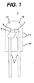
- Figure 1 schematically illustrates a LED 1 according to one embodiment of the present invention.
- the LED 1 contains a LED chip 4, which is electrically connected to a lead frame 5.
- the LED chip 4 may be directly electrically connected to an anode or cathode electrode of the lead frame 5 and connected by a lead 7 to the opposite cathode or anode electrode of the lead frame 5, as illustrated in Figure 1.
- the lead frame 5 supports the LED chip 4.
- the lead 7 may be omitted, and the LED chip 4 may straddle both electrodes of the lead frame 5 with the bottom of the LED chip 4 containing the contact layers, which contact both the anode and cathode electrode of the lead frame 5.
- the LED chip 4 may be connected with a separate lead 7 to the cathode and the anode electrode of the lead frame 5.
- the lead frame 5 connects to a power supply, such as a current or voltage source or to another circuit (not shown).
- the LED chip 4 emits radiation from the radiation emitting surface 9.
- the LED may emit visible, ultraviolet or infrared radiation.
- the LED chip may comprise any LED chip containing a p-n junction of any semiconductor layers capable of emitting the desired radiation.
- the LED chip may contain any desired Group III-V compound semiconductor layers, such as GaAs, GaAlAs, GaN, InGaN, GaP, etc., or Group II-VI compound semiconductor layers such ZnSe, ZnSSe, CdTe, etc., or Group IV-IV semiconductor layers, such as SiC.
- the LED chip 4 may also contain other layers, such as cladding layers, waveguide layers and contact layers.
- the LED 1 is packaged with an encapsulant 11 of the present invention.
- An alternative term for encapsulant is encapsulating material.
- the LED packaging includes encapsulant 11 located in a package, such as a shell 14.
- the shell may be any plastic or other material, such as polycarbonate, which is transparent to the LED radiation.
- the shell 14 may be omitted to simplify processing if encapsulant 11 has sufficient toughness and rigidity to be used without a shell.
- the outer surface of encapsulant 11 would act in some embodiments as a shell 14 or package.
- the shell 14 contains a light or radiation emitting surface 15 above the LED chip 4 and a non-emitting surface 16 adjacent to the lead frame 5.
- the radiation emitting surface 15 may be curved to act as a lens and/or may be colored to act as a filter.
- the non-emitting surface 16 may be opaque to the LED radiation, and may be made of opaque materials such as metal.
- the shell 14 may also contain a reflector around the LED chip 4, or other components, such as resistors, etc., if desired.
- encapsulating materials may optionally contain a phosphor to optimize the color output of the LED 1.
- a phosphor may be interspersed or mixed as a phosphor powder with encapsulant 11 or coated as a thin film on the LED chip 4 or coated on the inner surface of the shell 14. Any phosphor material may be used with the LED chip.
- a yellow emitting cerium doped yttrium aluminum garnet phosphor (YAG:Ce 3+ ) may be used with a blue emitting InGaN active layer LED chip to produce a visible yellow and blue light output which appears to a human observer.
- Other combinations of LED chips and phosphors may be used as desired.
- the packaged LED chip 4 is supported by the lead frame 5
- the LED 1 can have various other structures.
- the LED chip 4 may be supported by the bottom surface 16 of the shell 14 or by a pedestal (not shown) located on the bottom of the shell 14, instead of by the lead frame 5.
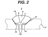
- the LED chip 4 of the LED 2 may be supported by a carrier substrate 17, as illustrated in Figure 2.
- the carrier substrate 17 comprises a lower portion of the LED package, and may comprise any material, such as plastic, metal or ceramic.
- the carrier substrate is made out of plastic and contains a groove 19 in which the LED chip 4 is located. The sides of the groove 19 may be coated with a reflective metal 21, such as aluminum, which acts as a reflector.
- the LED chip 4 may be formed over a flat surface of the substrate 17.
- the substrate 17 contains electrodes 23 that electrically contact the contact layers of the LED chip 4. Alternatively, the electrodes 23 may be electrically connected to the LED chip 4 with one or two leads as illustrated in Figure 1. If desired, the shell 14 or a glass plate may be formed over the encapsulant 11 to act as a lens or protective material.
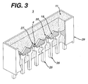
- a LED array 3 may be fabricated on a plastic substrate, as illustrated in Figure 3.
- the LED chips or die 4 are physically and electrically mounted on cathode leads 26.
- the top surfaces of the LED chips 4 are electrically connected to anode leads 25 with lead wires 27.
- the lead wires may be attached by known wire bonding techniques to a conductive chip pad.
- the leads 26, 25 comprise a lead frame and may be made of a metal, such as silver plated copper.
- the lead frame and LED chip array 3 are contained in a plastic package 29, such as a polycarbonate package.
- the polycarbonate comprises a bisphenol A polycarbonate.
- the plastic package 29 is filled with an encapsulant 11 of the present invention.
- the package 29 contains tapered interior sidewalls 18, which enclose the LED chips 4, and form a light spreading cavity 20, which ensures cross fluxing of LED light.
Applications Claiming Priority (2)
| Application Number | Priority Date | Filing Date | Title |
|---|---|---|---|
| US935409 | 1997-09-23 | ||
| US09/935,409 US6617401B2 (en) | 2001-08-23 | 2001-08-23 | Composition comprising cycloaliphatic epoxy resin, 4-methylhexahydrophthalic anhydride curing agent and boron catalyst |
Publications (2)
| Publication Number | Publication Date |
|---|---|
| EP1285938A1 true EP1285938A1 (de) | 2003-02-26 |
| EP1285938B1 EP1285938B1 (de) | 2006-01-25 |
Family
ID=25467073
Family Applications (1)
| Application Number | Title | Priority Date | Filing Date |
|---|---|---|---|
| EP02255685A Expired - Lifetime EP1285938B1 (de) | 2001-08-23 | 2002-08-14 | Epoxyharz Verkapselungszusammensetzung |
Country Status (4)
| Country | Link |
|---|---|
| US (2) | US6617401B2 (de) |
| EP (1) | EP1285938B1 (de) |
| JP (1) | JP2003176333A (de) |
| DE (1) | DE60208863T2 (de) |
Cited By (5)
| Publication number | Priority date | Publication date | Assignee | Title |
|---|---|---|---|---|
| WO2004107457A2 (en) * | 2003-05-30 | 2004-12-09 | Brasscorp Limited | Led inspection lamp, cluster led, and led with stabilizing agents |
| WO2005044890A1 (en) * | 2003-11-03 | 2005-05-19 | Union Carbide Chemicals & Plastics Technology Corporation | Tougher cycloaliphatic epoxide resins |
| WO2012158291A1 (en) * | 2011-05-13 | 2012-11-22 | Dow Global Technologies Llc | Insulation formulations |
| CN102985460A (zh) * | 2010-10-08 | 2013-03-20 | 株式会社大赛璐 | 环氧树脂用固化剂组合物、固化性树脂组合物及其固化物 |
| CN105936815A (zh) * | 2016-06-08 | 2016-09-14 | 天津德高化成光电科技有限责任公司 | 触变性环氧树脂、制备方法及在led芯片封装应用 |
Families Citing this family (33)
| Publication number | Priority date | Publication date | Assignee | Title |
|---|---|---|---|---|
| US20050288458A1 (en) * | 2002-07-29 | 2005-12-29 | Klemarczyk Philip T | Reworkable thermosetting resin composition |
| US6949771B2 (en) * | 2001-04-25 | 2005-09-27 | Agilent Technologies, Inc. | Light source |
| US6989412B2 (en) | 2001-06-06 | 2006-01-24 | Henkel Corporation | Epoxy molding compounds containing phosphor and process for preparing such compositions |
| US6617400B2 (en) * | 2001-08-23 | 2003-09-09 | General Electric Company | Composition of cycloaliphatic epoxy resin, anhydride curing agent and boron catalyst |
| US6617401B2 (en) * | 2001-08-23 | 2003-09-09 | General Electric Company | Composition comprising cycloaliphatic epoxy resin, 4-methylhexahydrophthalic anhydride curing agent and boron catalyst |
| US6734465B1 (en) * | 2001-11-19 | 2004-05-11 | Nanocrystals Technology Lp | Nanocrystalline based phosphors and photonic structures for solid state lighting |
| US6841802B2 (en) | 2002-06-26 | 2005-01-11 | Oriol, Inc. | Thin film light emitting diode |
| TWI302153B (en) * | 2003-02-27 | 2008-10-21 | Eternal Chemical Co Ltd | Material composition for packaging photo-sensitive elements and method of using the same |
| KR100537560B1 (ko) * | 2003-11-25 | 2005-12-19 | 주식회사 메디아나전자 | 2단계 큐어 공정을 포함하는 백색 발광 다이오드 소자의제조방법 |
| JP2005167091A (ja) * | 2003-12-04 | 2005-06-23 | Nitto Denko Corp | 光半導体装置 |
| JP3969661B2 (ja) * | 2003-12-12 | 2007-09-05 | スタンレー電気株式会社 | 熱硬化性樹脂組成物及び該組成物を封止剤とする発光ダイオード |
| KR100540848B1 (ko) * | 2004-01-02 | 2006-01-11 | 주식회사 메디아나전자 | 이중 몰드로 구성된 백색 발광다이오드 소자 및 그 제조방법 |
| US7875686B2 (en) * | 2004-08-18 | 2011-01-25 | Promerus Llc | Polycycloolefin polymeric compositions for semiconductor applications |
| US7446136B2 (en) * | 2005-04-05 | 2008-11-04 | Momentive Performance Materials Inc. | Method for producing cure system, adhesive system, and electronic device |
| US7405246B2 (en) * | 2005-04-05 | 2008-07-29 | Momentive Performance Materials Inc. | Cure system, adhesive system, electronic device |
| US8048819B2 (en) * | 2005-06-23 | 2011-11-01 | Momentive Performance Materials Inc. | Cure catalyst, composition, electronic device and associated method |
| EP2323178B1 (de) | 2005-08-04 | 2015-08-19 | Nichia Corporation | Licht emittierende Anordnung, Verfahren zu ihrer Herstellung, Formkörper und Abdichtglied |
| US8044412B2 (en) | 2006-01-20 | 2011-10-25 | Taiwan Semiconductor Manufacturing Company, Ltd | Package for a light emitting element |
| KR100665373B1 (ko) * | 2006-02-21 | 2007-01-09 | 삼성전기주식회사 | 발광다이오드 패키지 |
| US9502624B2 (en) | 2006-05-18 | 2016-11-22 | Nichia Corporation | Resin molding, surface mounted light emitting apparatus and methods for manufacturing the same |
| US8092735B2 (en) * | 2006-08-17 | 2012-01-10 | 3M Innovative Properties Company | Method of making a light emitting device having a molded encapsulant |
| JP5470680B2 (ja) * | 2007-02-06 | 2014-04-16 | 日亜化学工業株式会社 | 発光装置及びその製造方法並びに成形体 |
| US8330176B2 (en) * | 2007-02-13 | 2012-12-11 | 3M Innovative Properties Company | LED devices having lenses and methods of making same |
| US9944031B2 (en) * | 2007-02-13 | 2018-04-17 | 3M Innovative Properties Company | Molded optical articles and methods of making same |
| US20090065792A1 (en) | 2007-09-07 | 2009-03-12 | 3M Innovative Properties Company | Method of making an led device having a dome lens |
| JP5353629B2 (ja) * | 2008-11-14 | 2013-11-27 | 信越化学工業株式会社 | 熱硬化性樹脂組成物 |
| JP5478603B2 (ja) * | 2009-03-05 | 2014-04-23 | 新日鉄住金化学株式会社 | エポキシ樹脂組成物 |
| JP2012122002A (ja) | 2010-12-09 | 2012-06-28 | Daicel Corp | 付加硬化性メタロシロキサン化合物 |
| US8486214B2 (en) * | 2011-09-27 | 2013-07-16 | Source Photonics, Inc. | Ramped, variable power UV adhesive cure process for improved alignment |
| JP5885126B2 (ja) * | 2012-05-02 | 2016-03-15 | 川崎化成工業株式会社 | エポキシ化合物及びその製造方法ならびにエポキシ樹脂組成物及びその硬化物 |
| TWI494339B (zh) | 2012-10-23 | 2015-08-01 | Ind Tech Res Inst | 部分酯化環氧樹脂及應用其製成之環氧樹脂組成物及其製法 |
| JP6517043B2 (ja) * | 2015-02-25 | 2019-05-22 | ルネサスエレクトロニクス株式会社 | 光結合装置、光結合装置の製造方法および電力変換システム |
| DE102016106031A1 (de) | 2016-04-01 | 2017-10-05 | Dr. Neidlinger Holding Gmbh | Heißhärtendes Zweikomponenten-Epoxidharz |
Citations (6)
| Publication number | Priority date | Publication date | Assignee | Title |
|---|---|---|---|---|
| US4026862A (en) * | 1974-02-11 | 1977-05-31 | Westinghouse Electric Corporation | Carboxylic acid storage stabilizers for latent catalyst cured epoxy resins |
| JPH04209624A (ja) * | 1990-12-10 | 1992-07-31 | Toshiba Chem Corp | 光半導体封止用エポキシ樹脂組成物 |
| US5145889A (en) * | 1988-12-23 | 1992-09-08 | Kabushiki Kaisha Toshiba | Acid anhydride-cured epoxy resin encapsulant with triorganothiophosphite |
| EP0702042A1 (de) * | 1994-02-24 | 1996-03-20 | New Japan Chemical Co.,Ltd. | Epoxydharz, verfahren zu ihrer herstellung und photohärtbare harzzusammensetzung und pulverlackzusammensetzung, die diesen harz enthalten |
| US6218482B1 (en) * | 1994-02-24 | 2001-04-17 | New Japan Chemical Co., Ltd. | Epoxy resin, process for preparing the resin and photo-curable resin composition and resin composition for powder coatings containing the epoxy resin |
| WO2002019440A1 (en) * | 2000-09-01 | 2002-03-07 | General Electric Company | Encapsulants for solid state devices |
Family Cites Families (14)
| Publication number | Priority date | Publication date | Assignee | Title |
|---|---|---|---|---|
| NL299937A (de) * | 1963-10-30 | |||
| US4336367A (en) | 1969-05-15 | 1982-06-22 | The United States Of America As Represented By The Secretary Of The Navy | Epoxy adhesive composition |
| DE2642465C3 (de) | 1976-09-21 | 1981-01-22 | Siemens Ag, 1000 Berlin Und 8000 Muenchen | Verfahren zur Herstellung einer VerguBmasse |
| US4454201A (en) | 1981-02-05 | 1984-06-12 | Goodyear Aerospace Corporation | Transparencies produced from epoxy resins cured with adducts of boroxines and interlayers of mercaptan resins |
| JPS5867051A (ja) * | 1981-10-16 | 1983-04-21 | Hitachi Chem Co Ltd | 半導体素子封止用エポキシ樹脂組成物 |
| JPS60137046A (ja) * | 1984-11-02 | 1985-07-20 | Nitto Electric Ind Co Ltd | 発光素子または受光素子封止体 |
| US4873309A (en) * | 1987-06-08 | 1989-10-10 | Shell Oil Company | Stabilized flame-retardant epoxy resin composition from a brominated epoxy resin and a vinyl monomer diluent |
| US4999699A (en) * | 1990-03-14 | 1991-03-12 | International Business Machines Corporation | Solder interconnection structure and process for making |
| US5198479A (en) | 1990-08-24 | 1993-03-30 | Shin-Etsu Chemical Company Limited | Light transmissive epoxy resin compositions and optical semiconductor devices encapsulated therewith |
| US5212261A (en) * | 1990-12-17 | 1993-05-18 | Henkel Research Corporation | Latent, heat-curable epoxy resin compositions containing metal carboxylate curing systems |
| JPH065464A (ja) * | 1992-06-19 | 1994-01-14 | Hitachi Chem Co Ltd | コンデンサ用エポキシ樹脂組成物 |
| CN1129648C (zh) * | 1997-01-21 | 2003-12-03 | 陶氏环球技术公司 | 用于环氧固化体系的潜伏催化剂 |
| US6180696B1 (en) * | 1997-02-19 | 2001-01-30 | Georgia Tech Research Corporation | No-flow underfill of epoxy resin, anhydride, fluxing agent and surfactant |
| US6617401B2 (en) * | 2001-08-23 | 2003-09-09 | General Electric Company | Composition comprising cycloaliphatic epoxy resin, 4-methylhexahydrophthalic anhydride curing agent and boron catalyst |
-
2001
- 2001-08-23 US US09/935,409 patent/US6617401B2/en not_active Expired - Fee Related
-
2002
- 2002-08-14 EP EP02255685A patent/EP1285938B1/de not_active Expired - Lifetime
- 2002-08-14 DE DE60208863T patent/DE60208863T2/de not_active Expired - Fee Related
- 2002-08-22 JP JP2002241363A patent/JP2003176333A/ja not_active Withdrawn
-
2003
- 2003-04-29 US US10/425,904 patent/US6809162B2/en not_active Expired - Fee Related
Patent Citations (6)
| Publication number | Priority date | Publication date | Assignee | Title |
|---|---|---|---|---|
| US4026862A (en) * | 1974-02-11 | 1977-05-31 | Westinghouse Electric Corporation | Carboxylic acid storage stabilizers for latent catalyst cured epoxy resins |
| US5145889A (en) * | 1988-12-23 | 1992-09-08 | Kabushiki Kaisha Toshiba | Acid anhydride-cured epoxy resin encapsulant with triorganothiophosphite |
| JPH04209624A (ja) * | 1990-12-10 | 1992-07-31 | Toshiba Chem Corp | 光半導体封止用エポキシ樹脂組成物 |
| EP0702042A1 (de) * | 1994-02-24 | 1996-03-20 | New Japan Chemical Co.,Ltd. | Epoxydharz, verfahren zu ihrer herstellung und photohärtbare harzzusammensetzung und pulverlackzusammensetzung, die diesen harz enthalten |
| US6218482B1 (en) * | 1994-02-24 | 2001-04-17 | New Japan Chemical Co., Ltd. | Epoxy resin, process for preparing the resin and photo-curable resin composition and resin composition for powder coatings containing the epoxy resin |
| WO2002019440A1 (en) * | 2000-09-01 | 2002-03-07 | General Electric Company | Encapsulants for solid state devices |
Non-Patent Citations (1)
| Title |
|---|
| PATENT ABSTRACTS OF JAPAN vol. 016, no. 548 (C - 1005) 18 November 1992 (1992-11-18) * |
Cited By (8)
| Publication number | Priority date | Publication date | Assignee | Title |
|---|---|---|---|---|
| WO2004107457A2 (en) * | 2003-05-30 | 2004-12-09 | Brasscorp Limited | Led inspection lamp, cluster led, and led with stabilizing agents |
| WO2004107457A3 (en) * | 2003-05-30 | 2005-11-03 | Brasscorp Ltd | Led inspection lamp, cluster led, and led with stabilizing agents |
| WO2005044890A1 (en) * | 2003-11-03 | 2005-05-19 | Union Carbide Chemicals & Plastics Technology Corporation | Tougher cycloaliphatic epoxide resins |
| CN102985460A (zh) * | 2010-10-08 | 2013-03-20 | 株式会社大赛璐 | 环氧树脂用固化剂组合物、固化性树脂组合物及其固化物 |
| CN102985460B (zh) * | 2010-10-08 | 2017-02-22 | 株式会社大赛璐 | 环氧树脂用固化剂组合物、固化性树脂组合物及其固化物 |
| WO2012158291A1 (en) * | 2011-05-13 | 2012-11-22 | Dow Global Technologies Llc | Insulation formulations |
| CN105936815A (zh) * | 2016-06-08 | 2016-09-14 | 天津德高化成光电科技有限责任公司 | 触变性环氧树脂、制备方法及在led芯片封装应用 |
| CN105936815B (zh) * | 2016-06-08 | 2018-11-30 | 天津德高化成光电科技有限责任公司 | 触变性环氧树脂、制备方法及在led芯片封装应用 |
Also Published As
| Publication number | Publication date |
|---|---|
| DE60208863D1 (de) | 2006-04-13 |
| US6617401B2 (en) | 2003-09-09 |
| DE60208863T2 (de) | 2006-09-28 |
| US6809162B2 (en) | 2004-10-26 |
| US20030071368A1 (en) | 2003-04-17 |
| JP2003176333A (ja) | 2003-06-24 |
| EP1285938B1 (de) | 2006-01-25 |
| US20030208008A1 (en) | 2003-11-06 |
Similar Documents
| Publication | Publication Date | Title |
|---|---|---|
| EP1285938B1 (de) | Epoxyharz Verkapselungszusammensetzung | |
| US6617400B2 (en) | Composition of cycloaliphatic epoxy resin, anhydride curing agent and boron catalyst | |
| US7144763B2 (en) | Epoxy resin compositions, solid state devices encapsulated therewith and method | |
| US6507049B1 (en) | Encapsulants for solid state devices | |
| EP1408087B1 (de) | Epoxy-polysiloxanharzzusammensetzungen, damit eingekapselte Halbleitereinrichtungen und Verfahren | |
| JP2008007782A (ja) | オプトエレクトロニックデバイス | |
| EP1505121B1 (de) | Härtbare zusammensetzung, härtendes produkt, herstellungsverfahren dafür und mit dem härtenden produkt versiegelte lichtemittierende diode | |
| EP2532693A1 (de) | Härtbare epoxidharzzusammensetzung | |
| US20070295956A1 (en) | Optoelectronic device | |
| US20080160317A1 (en) | Optoelectronic device | |
| US20070299162A1 (en) | Optoelectronic device | |
| US20070295983A1 (en) | Optoelectronic device | |
| JP2012041403A (ja) | 熱硬化性エポキシ樹脂組成物及び半導体装置 | |
| US20080001140A1 (en) | Optoelectronic device | |
| JP2006299073A (ja) | 光半導体封止用樹脂組成物 | |
| KR20160094368A (ko) | 광반도체 장치용 열경화성 수지 조성물 및 그것을 이용하여 얻어지는 광반도체 장치용 리드 프레임, 그리고 광반도체 장치 | |
| KR20140098679A (ko) | 경화성 수지 조성물 및 광 반도체 밀봉용 수지 조성물 | |
| TW201446873A (zh) | 光半導體反射器用環氧樹脂組成物、光半導體裝置用熱硬化性樹脂組成物及使用其製得之光半導體裝置用引線框、密封型光半導體元件以及光半導體裝置 | |
| KR101405532B1 (ko) | 에폭시 수지 조성물 및 이를 포함하는 광반도체 장치 |
Legal Events
| Date | Code | Title | Description |
|---|---|---|---|
| PUAI | Public reference made under article 153(3) epc to a published international application that has entered the european phase |
Free format text: ORIGINAL CODE: 0009012 |
|
| AK | Designated contracting states |
Designated state(s): AT BE BG CH CY CZ DE DK EE ES FI FR GB GR IE IT LI LU MC NL PT SE SK TR Kind code of ref document: A1 Designated state(s): AT BE BG CH CY CZ DE DK EE ES FI FR GB GR IE IT LI LU MC NL PT SE SK TR |
|
| AX | Request for extension of the european patent |
Extension state: AL LT LV MK RO SI |
|
| 17P | Request for examination filed |
Effective date: 20030826 |
|
| AKX | Designation fees paid |
Designated state(s): DE FR GB IT |
|
| 17Q | First examination report despatched |
Effective date: 20040206 |
|
| GRAP | Despatch of communication of intention to grant a patent |
Free format text: ORIGINAL CODE: EPIDOSNIGR1 |
|
| GRAS | Grant fee paid |
Free format text: ORIGINAL CODE: EPIDOSNIGR3 |
|
| GRAA | (expected) grant |
Free format text: ORIGINAL CODE: 0009210 |
|
| AK | Designated contracting states |
Kind code of ref document: B1 Designated state(s): DE FR GB IT |
|
| PG25 | Lapsed in a contracting state [announced via postgrant information from national office to epo] |
Ref country code: IT Free format text: LAPSE BECAUSE OF FAILURE TO SUBMIT A TRANSLATION OF THE DESCRIPTION OR TO PAY THE FEE WITHIN THE PRESCRIBED TIME-LIMIT;WARNING: LAPSES OF ITALIAN PATENTS WITH EFFECTIVE DATE BEFORE 2007 MAY HAVE OCCURRED AT ANY TIME BEFORE 2007. THE CORRECT EFFECTIVE DATE MAY BE DIFFERENT FROM THE ONE RECORDED. Effective date: 20060125 |
|
| REG | Reference to a national code |
Ref country code: GB Ref legal event code: FG4D |
|
| REF | Corresponds to: |
Ref document number: 60208863 Country of ref document: DE Date of ref document: 20060413 Kind code of ref document: P |
|
| PGFP | Annual fee paid to national office [announced via postgrant information from national office to epo] |
Ref country code: DE Payment date: 20061002 Year of fee payment: 5 |
|
| PLBE | No opposition filed within time limit |
Free format text: ORIGINAL CODE: 0009261 |
|
| STAA | Information on the status of an ep patent application or granted ep patent |
Free format text: STATUS: NO OPPOSITION FILED WITHIN TIME LIMIT |
|
| 26N | No opposition filed |
Effective date: 20061026 |
|
| GBPC | Gb: european patent ceased through non-payment of renewal fee |
Effective date: 20060814 |
|
| PG25 | Lapsed in a contracting state [announced via postgrant information from national office to epo] |
Ref country code: GB Free format text: LAPSE BECAUSE OF NON-PAYMENT OF DUE FEES Effective date: 20060814 |
|
| PG25 | Lapsed in a contracting state [announced via postgrant information from national office to epo] |
Ref country code: FR Free format text: LAPSE BECAUSE OF FAILURE TO SUBMIT A TRANSLATION OF THE DESCRIPTION OR TO PAY THE FEE WITHIN THE PRESCRIBED TIME-LIMIT Effective date: 20070316 |
|
| PG25 | Lapsed in a contracting state [announced via postgrant information from national office to epo] |
Ref country code: DE Free format text: LAPSE BECAUSE OF NON-PAYMENT OF DUE FEES Effective date: 20080301 |
|
| PG25 | Lapsed in a contracting state [announced via postgrant information from national office to epo] |
Ref country code: FR Free format text: LAPSE BECAUSE OF FAILURE TO SUBMIT A TRANSLATION OF THE DESCRIPTION OR TO PAY THE FEE WITHIN THE PRESCRIBED TIME-LIMIT Effective date: 20060125 |