EP1285757A1 - Verfahren und Druckmaschine zum Ermitteln von Registerfehlern - Google Patents
Verfahren und Druckmaschine zum Ermitteln von Registerfehlern Download PDFInfo
- Publication number
- EP1285757A1 EP1285757A1 EP02006044A EP02006044A EP1285757A1 EP 1285757 A1 EP1285757 A1 EP 1285757A1 EP 02006044 A EP02006044 A EP 02006044A EP 02006044 A EP02006044 A EP 02006044A EP 1285757 A1 EP1285757 A1 EP 1285757A1
- Authority
- EP
- European Patent Office
- Prior art keywords
- register
- sheet
- printing
- conveyor belt
- register mark
- Prior art date
- Legal status (The legal status is an assumption and is not a legal conclusion. Google has not performed a legal analysis and makes no representation as to the accuracy of the status listed.)
- Granted
Links
- 238000000034 method Methods 0.000 title claims abstract description 9
- 238000001514 detection method Methods 0.000 claims abstract description 11
- 230000007246 mechanism Effects 0.000 abstract 1
- 238000003384 imaging method Methods 0.000 description 9
- 230000000694 effects Effects 0.000 description 5
- 238000006073 displacement reaction Methods 0.000 description 2
- 239000003086 colorant Substances 0.000 description 1
- 230000000994 depressogenic effect Effects 0.000 description 1
- 230000005484 gravity Effects 0.000 description 1
- 239000000463 material Substances 0.000 description 1
- 230000035945 sensitivity Effects 0.000 description 1
- 238000000926 separation method Methods 0.000 description 1
Images

Classifications
-
- B—PERFORMING OPERATIONS; TRANSPORTING
- B41—PRINTING; LINING MACHINES; TYPEWRITERS; STAMPS
- B41F—PRINTING MACHINES OR PRESSES
- B41F33/00—Indicating, counting, warning, control or safety devices
- B41F33/0081—Devices for scanning register marks
-
- B—PERFORMING OPERATIONS; TRANSPORTING
- B41—PRINTING; LINING MACHINES; TYPEWRITERS; STAMPS
- B41P—INDEXING SCHEME RELATING TO PRINTING, LINING MACHINES, TYPEWRITERS, AND TO STAMPS
- B41P2233/00—Arrangements for the operation of printing presses
- B41P2233/50—Marks on printed material
- B41P2233/52—Marks on printed material for registering
Definitions
- the invention relates to a method according to claim 1 and to a Printing machine for carrying out the method according to claim 3.
- registration marks are determined by register marks used by what deviations from the correct position pressure from Operator of the printing machine can be determined and measured.
- the registration with the help of sensors in determined and calculated by the printing press. For this, the sensors record the Register marks on the conveyor belt or the sheet and determine using the Position of the register marks, whether the printing takes place without errors.
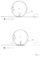
- the upper illustration shows a side view of an intermediate cylinder 25 of a printing press, on which an image of an imaging cylinder 23 is applied.
- the intermediate cylinder 25 moves at the angular velocity ⁇ 1 in the direction of the curved arrow and presses with the force F on the surface of an endless conveyor belt 1 which moves to the left in the direction of the arrow.
- ⁇ 1 in the direction of the curved arrow
- the lower illustration is similar to the upper illustration, wherein in the lower illustration there is a sheet 3 of paper on the conveyor belt 1 which is caused by gravity and essentially by electrostatic attractive forces is held on the conveyor belt 1.
- the curve 3 under the intermediate cylinder 25 influences the movement of the intermediate cylinder 25 in such a way that the speed of the intermediate cylinder 25 changes in comparison to the illustration above.
- the conveyor belt 1 in the region of the intermediate cylinder 25 is depressed in the lower illustration compared to the upper illustration by approximately the length which corresponds to the thickness of the sheet 3.
- the angular velocity ⁇ of the intermediate cylinder 25 of the lower illustration is now ⁇ 2 compared to the upper illustration due to the arc 3 between the conveyor belt 1 and the intermediate cylinder 25. This change in speed due to the sheet 3 leads to register errors during printing, as described in detail below.
- FIG. 2 shows two representations, each with a top view of a section of a conveyor belt 1 that moves in the direction of the arrow.
- the upper illustration shows a first register mark 5 and a second register mark 6, the front edges of which have a time interval between the detection by a second sensor 13 behind the printing modules of the printing press, which can be clearly described by a cycle number, in this case, the number of cycles TaktzahI SOLL.
- the lower illustration shows a section of a conveyor belt 1, similar to that of the upper illustration.
- the sheet 3 is located on the conveyor belt 1.
- an intermediate cylinder 25 presses on the section 3 of the conveyor belt 1 according to FIG , as described, the angular velocity of the intermediate cylinder 25 from ⁇ 1 to ⁇ 2 .
- the sheet 3 exerts a braking effect on the movement of the intermediate cylinder 25 on the conveyor belt 1.
- the speed change of the intermediate cylinder 25 with sheet 3 leads to errors in the transfer of the image from the intermediate cylinder 25 to the sheet 3, since the ratio of the speeds of the conveyor belt 1 and the angular velocity ⁇ of the intermediate cylinder 25 changes, this ratio for the Applying the image to the sheet 3 in register is essential.
- a calibration run for determining the register error is carried out with the aid of an arrangement of the lower illustration in FIG. 2.
- the first sensor 12 first detects the front edge of the first register mark 5 and then the front edge of the second register mark 6, corresponding to the illustration above in FIG. 2.
- the number of cycles between the detection of the front edges of the register marks 5, 6 is not the desired number of cycles , but deviates by an amount by which the second register mark 6 is later applied to the sheet 3 due to the effect described above.
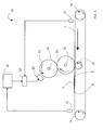
- Fig. 3 shows a schematic side view of a device 10 with one part a printing module of a printing machine above the conveyor belt 1.
- the printing press has several printing modules, for each color Print module, whereby the individual colors are combined to form the overall picture.
- the conveyor belt 1 is driven by the drive on the second deflection roller 14 and moves in the direction of the arrow.
- the first deflection roller 16, the second deflection roller 14, a pressure roller 27 for providing a counterforce to the pressing force of the intermediate cylinder 25, the intermediate cylinder 25 and the imaging cylinder 23 move in the directions shown in FIG. 3.
- the imaging cylinder 23 and the intermediate cylinder 25 have a first encoder 24 or a second encoder 26, which has a specific angle of rotation of the imaging cylinder 23 or the intermediate cylinder 25 so that the angle of rotation is known at all times.
- a first sensor 12 at the beginning of the conveyor belt 1 detects the leading edge of the sheet 3 and transmits in response a signal to a clock counter 20.
- a clock counter 20 As a result of this signal another Generated signal, which the imaging of the imaging cylinder 23 by means of a Imaging device 22 triggers.
- the further signal occurs exactly to one Time that the image transferred to the imaging cylinder 23 on the Rolled intermediate cylinder 25 and from this in exactly the right place on the Sheet 3 is transmitted. This is by knowing the speed of the conveyor belt 1 with arc 3 and the distance between the first sensor 12 and the this generated sensor signal from the transfer point of the image between the intermediate cylinder 25 and the sheet 3, the printing nip or nip possible.
- the time difference between the further signal and the application of the image, which is caused by the further signal is defined here as a delay time, which is uniquely assigned a delay value, which is represented as a number of cycles.
- a delay time which is uniquely assigned a delay value, which is represented as a number of cycles.
- the first register mark 5 is printed from the intermediate cylinder 25 onto the conveyor belt 1, as described above. The printing takes place in such a way that the first register mark 5 is followed by a sheet 3 on the conveyor belt 1.
- the intermediate cylinder 25 of the printing module applies the second register mark 6 to the conveyor belt 1.
- the conveyor belt 1 consequently has an arrangement as shown in FIG. 2 below.
- the second sensor 13 at the end of the printing module detects the front edge of the first register mark 5 and the front edge of the second register mark 6 and transmits signals to a correction device 30 which detects the Start the clock counter 20 when the front edge of the first register mark 5 is detected and stop when the front edge of the second register mark 6 is detected.
- a cycle number of cycle numbers IST is obtained which relates to the distance from the front edge of the first register mark 5 to the front edge of the second register mark 6 and can be converted into this distance using the speed of the conveyor belt 1.
- the number of cycles, cycle number IST can be assigned to the time which elapses from the detection of the front edge of the first register mark 5 to the detection of the front edge of the second register mark 6, since a clock number can be assigned a time in a unique manner.
- the cycle number cycle number ACTUAL differs from the cycle number cycle number TARGET because the sheet 3 causes a change in the angular velocity ⁇ of the intermediate cylinder 25 in relation to the conveyor belt 1 when passing through the nip between the intermediate cylinder 25 and the conveyor belt 1. This effect cannot be determined for the first register mark 5, since this is registered in front of the sheet 3, as can be seen in FIG. 3.
- the effect can be determined by the difference in the number of cycles DIFF .
- the difference in the number of cycles DIFF is averaged.
- the delay value shown as the number of cycles is changed by the difference in the number of cycles DIFF .
- the corrected delay value is used for the pressure following the calibration run. Consequently, the imaging device 22 begins to transmit the corresponding image at a different time than without the calibration run described above.
- image denotes image lines, image sections and images of individual color separations of the printing modules, which are composed to form the overall image.
- the above description includes exemplary embodiments with sheet 3. However, the invention extends to all types of non-endless printing material and is not limited to sheet 3.
Landscapes
- Inking, Control Or Cleaning Of Printing Machines (AREA)
- Controlling Sheets Or Webs (AREA)
Abstract
Description
- Fig. 1
- zeigt zwei Darstellungen zur Beschreibung des Registerfehlers, wobei die obere Darstellung einen Bedruckzylinder auf einem Transportband ohne Beeinflussung der Drehgeschwindigkeit des Bedruckzylinders durch einen Bogen darstellt und die untere Darstellung mit Beeinflussung,
- Fig. 2
- zeigt einen Teil eines Transportbands, wobei auf dem Transportband eine erste Registermarke und eine zweite Registermarke aufgebracht sind, zwischen denen sich ein Bogen befindet,
- Fig. 3
- zeigt eine Einrichtung mit einem Teil eines Druckmoduls bezüglich der Erfindung.
Claims (5)
- Verfahren zum Ermitteln von Registerfehlern beim Druck, welche durch eine Geschwindigkeitsänderung eines Druckzylinders, insbesondere aufgrund eines Bogens (3), verursacht sind, gekennzeichnet durch ein Aufbringen von wenigstens einer ersten Registermarke (5) auf das Transportband (1) vor einem Bogen (3) und wenigstens einer zweiten Registermarke (6) auf das Transportband (1) hinter dem Bogen (3), ein Erfassen der ersten Registermarke (5) und der zweiten Registermarke (6), ein Berechnen einer Taktzahl zwischen dem Erfassen der ersten Registermarke (5) und der zweiten Registermarke (6) und einen Vergleich der berechneten Taktzahl mit einem Sollwert.
- Verfahren nach Anspruch 1, dadurch gekennzeichnet, dass der Bogen (3) von einem ersten Sensor (12) vor den Druckmodulen erfasst wird, welcher beim Erkennen des Bogens (3) ein Startsignal zum Starten eines Taktzählers (20) erzeugt, die Registermarken (5, 6) von den Druckmodulen aufgebracht werden und die Registermarken (5, 6) von einem zweiten Sensor (13) hinter den Druckmodulen erfasst werden, welcher ein Stopsignal zum Anhalten des Taktzählers (20) erzeugt.
- Druckmaschine, vorzugsweise zur Durchführung des Verfahrens nach Anspruch 1, gekennzeichnet durch eine Einrichtung (10) zum Ermitteln von Registerfehlern beim Druck, welche durch Geschwindigkeitsänderungen eines Druckzylinders aufgrund eines Bogens (3) verursacht sind.
- Druckmaschine nach Anspruch 3, gekennzeichnet durch eine Korrektureinrichtung (30) zum Korrigieren des ermittelten Registerfehlers.
- Druckmaschine nach Anspruch 3 oder 4, gekennzeichnet durch einen ersten Sensor (12) zum Erzeugen eines Startsignals zum Starten eines Taktzählers (20) beim Erkennen eines Bogens (3), Druckmodule zum Aufbringen von Registermarken (5, 6), einen zweiten Sensor (13) zum Erzeugen eines Stopsignals zum Anhalten des Taktzählers (20) und eine Korrektureinrichtung (30) zum Korrigieren von Registerfehlern beim Druck, welche durch Geschwindigkeitsänderungen eines Druckzylinders aufgrund eines Bogen (3) verursacht sind.
Applications Claiming Priority (2)
| Application Number | Priority Date | Filing Date | Title |
|---|---|---|---|
| DE10141035A DE10141035A1 (de) | 2001-08-22 | 2001-08-22 | Verfahren und Druckmaschine zum Ermitteln von Registerfehlern |
| DE10141035 | 2001-08-22 |
Publications (2)
| Publication Number | Publication Date |
|---|---|
| EP1285757A1 true EP1285757A1 (de) | 2003-02-26 |
| EP1285757B1 EP1285757B1 (de) | 2006-10-18 |
Family
ID=7696180
Family Applications (1)
| Application Number | Title | Priority Date | Filing Date |
|---|---|---|---|
| EP02006044A Expired - Lifetime EP1285757B1 (de) | 2001-08-22 | 2002-03-16 | Verfahren und Druckmaschine zum Ermitteln von Registerfehlern |
Country Status (4)
| Country | Link |
|---|---|
| US (1) | US6718879B2 (de) |
| EP (1) | EP1285757B1 (de) |
| JP (1) | JP2003072035A (de) |
| DE (2) | DE10141035A1 (de) |
Families Citing this family (15)
| Publication number | Priority date | Publication date | Assignee | Title |
|---|---|---|---|---|
| JP3687634B2 (ja) * | 2002-07-26 | 2005-08-24 | ブラザー工業株式会社 | プリンタ |
| DE10241609A1 (de) * | 2002-09-07 | 2004-03-18 | Nexpress Solutions Llc | Verfahren und Steuerungseinrichtung zum Bestimmen eines Registerfehlers |
| DE10305047B4 (de) * | 2002-10-11 | 2010-08-12 | Eastman Kodak Company | Verfahren zur Kalibrierung des passergenauen Druckprozesses einer Farbdruckmaschine |
| DE10304763A1 (de) | 2003-02-05 | 2004-08-26 | Nexpress Solutions Llc | Verfahren zur Korrektur der Kalibrierung eines passergenauen Druckprozesses |
| KR100472487B1 (ko) * | 2003-03-07 | 2005-03-09 | 삼성전자주식회사 | 화상 정렬 오차 보정방법 및 장치 |
| DE10333626A1 (de) * | 2003-07-24 | 2005-02-17 | Robert Bürkle GmbH | Vorrichtung zum Bedrucken von flächigen Werkstücken |
| CA2680589A1 (en) | 2007-03-14 | 2008-09-18 | Universita' Degli Studi Di Milano - Bicocca | Modulator compounds of the drug resistance in epithelial tumour cells |
| GB0705260D0 (en) * | 2007-03-19 | 2007-04-25 | Field Group Plc | Rotary embossing |
| US20100196072A1 (en) | 2009-02-03 | 2010-08-05 | Xerox Corporation | Modular color xerographic printing architecture |
| US8526054B2 (en) * | 2009-04-27 | 2013-09-03 | Xerox Corporation | Dynamic image registration apparatus and method |
| JP2015230394A (ja) * | 2014-06-05 | 2015-12-21 | 株式会社リコー | 画像形成装置 |
| EP3028969A1 (de) | 2014-11-18 | 2016-06-08 | OCE-Technologies B.V. | Kalibrierungssystem für einen fördermechanismus und verfahren zum kalibrieren einer fördereinrichtung |
| US11829084B2 (en) | 2021-09-28 | 2023-11-28 | Eastman Kodak Company | Registration of white toner in an electrophotographic printer |
| US11822262B2 (en) | 2021-09-28 | 2023-11-21 | Eastman Kodak Company | Registration of white toner using sensing system with colored reflector plate |
| CN116766762B (zh) * | 2022-03-08 | 2025-08-05 | 长声工业股份有限公司 | 轮转式印刷设备及其方法 |
Citations (2)
| Publication number | Priority date | Publication date | Assignee | Title |
|---|---|---|---|---|
| US5875380A (en) * | 1997-02-18 | 1999-02-23 | Ricoh Company, Ltd. | Image forming apparatus eliminating influence of fluctuation in speed of a conveying belt to correction of offset in color registration |
| EP1005981A1 (de) * | 1998-11-25 | 2000-06-07 | MAN Roland Druckmaschinen AG | Vorrichtung und Verfahren zur Kompensation von Schlupf einer Druckformhülse |
Family Cites Families (6)
| Publication number | Priority date | Publication date | Assignee | Title |
|---|---|---|---|---|
| JPS5625454A (en) | 1979-01-11 | 1981-03-11 | Satoshi Kawakatsu | Textile printing device |
| JP3454996B2 (ja) * | 1995-12-22 | 2003-10-06 | 富士通株式会社 | カラー画像形成装置 |
| US5963240A (en) * | 1996-02-02 | 1999-10-05 | Ricoh Company, Ltd. | Deflecting mirror adjusting device for an image forming apparatus |
| JPH10142895A (ja) * | 1996-11-07 | 1998-05-29 | Ricoh Co Ltd | カラー画像形成装置 |
| JPH10198110A (ja) * | 1996-11-18 | 1998-07-31 | Ricoh Co Ltd | カラー画像形成方法 |
| JP2000272089A (ja) | 1999-03-24 | 2000-10-03 | Tdk Corp | 印刷位置ズレ補正方法 |
-
2001
- 2001-08-22 DE DE10141035A patent/DE10141035A1/de not_active Withdrawn
-
2002
- 2002-03-16 DE DE50208478T patent/DE50208478D1/de not_active Expired - Lifetime
- 2002-03-16 EP EP02006044A patent/EP1285757B1/de not_active Expired - Lifetime
- 2002-07-30 US US10/208,216 patent/US6718879B2/en not_active Expired - Lifetime
- 2002-08-21 JP JP2002240822A patent/JP2003072035A/ja not_active Abandoned
Patent Citations (2)
| Publication number | Priority date | Publication date | Assignee | Title |
|---|---|---|---|---|
| US5875380A (en) * | 1997-02-18 | 1999-02-23 | Ricoh Company, Ltd. | Image forming apparatus eliminating influence of fluctuation in speed of a conveying belt to correction of offset in color registration |
| EP1005981A1 (de) * | 1998-11-25 | 2000-06-07 | MAN Roland Druckmaschinen AG | Vorrichtung und Verfahren zur Kompensation von Schlupf einer Druckformhülse |
Also Published As
| Publication number | Publication date |
|---|---|
| EP1285757B1 (de) | 2006-10-18 |
| JP2003072035A (ja) | 2003-03-12 |
| US20030037689A1 (en) | 2003-02-27 |
| DE10141035A1 (de) | 2003-03-20 |
| DE50208478D1 (de) | 2006-11-30 |
| US6718879B2 (en) | 2004-04-13 |
Similar Documents
| Publication | Publication Date | Title |
|---|---|---|
| EP1285757B1 (de) | Verfahren und Druckmaschine zum Ermitteln von Registerfehlern | |
| DE69806653T2 (de) | Verfahren zum Aufbringen von Längsmarken einer Rolle auf Druckmaterial | |
| EP2392459B1 (de) | Verfahren und Vorrichtung zur Registersteuerung einer Druckmaschine | |
| EP1285756B1 (de) | Verfahren und Druckmaschine zum Ermitteln von Registerfehlern | |
| EP1572457B1 (de) | Vorregistereinstellung | |
| EP1157837A2 (de) | Verfahren und Vorrichtung zur Registereinstellung an einer Mehrfarbendruckmaschine | |
| EP3539777B1 (de) | Verfahren und vorrichtung zum korrigieren einer druckposition eines druckwerks sowie druckmaschine | |
| DE10139310B4 (de) | Verfahren zum Ermitteln von START OF FRAME-Korrekturdaten und START OF LINE-Korrekturdaten zur Registereinstellung für Druckmaschinen beim Mehrfarbdruck | |
| DE102005019566A1 (de) | Druckmaschine und Verfahren zur Registerkorrektur | |
| DE10208597B4 (de) | Verfahren zum Vermeiden von Registerfehlern bei einer Druckmaschine | |
| WO2002042075A1 (de) | Verfahren zur regelung eines umfangsregisters in einer rollenrotationsdruckmaschine | |
| DE102004007367A1 (de) | Verfahren und Druckmaschine zum Erfassen von Marken | |
| EP1759844B1 (de) | Verfahren zur Druckkorrektur | |
| EP1396341B1 (de) | Verfahren und Steuerungseinrichtung zum Bestimmen eines Registerfehlers | |
| DE102009047776B4 (de) | Verfahren und Vorrichtung zum Messen einer Laufrichtung einer Substratbahn | |
| DE10227766A1 (de) | Verfahren und Steuerungseinrichtung zum Vermeiden von Registerfehlern | |
| EP2862715A2 (de) | Druckmaschine | |
| DE102011008359B3 (de) | Verfahren zur Registerregelung mit frei wählbaren Marken | |
| DE102004015101B4 (de) | Verfahren und Sensoreinrichtung zum Steuern eines endlosen, eine Naht aufweisenden Transportmediums für eine Druckmaschine | |
| EP4159442A1 (de) | Messwertkorrektur einer referenzmarke auf einer warenbahn | |
| DE10036989C2 (de) | Bahnverarbeitende Maschine und Verfahren zu deren Betrieb | |
| DE10306442A1 (de) | Verfahren und Einrichtung zum Erfassen einer Registermarke | |
| DE102005030280B3 (de) | Verfahren zum Betrieb einer bahnverarbeitenden Maschine | |
| DE102015200148B4 (de) | Verfahren zur Anpassung mindestens einer Länge einer auf mehreren Druckbogen jeweils gleich groß drucktechnisch auszubildenden Fläche | |
| DE10318997A1 (de) | Verfahren und Steuerungseinrichtung zum Vermeiden von Registerfehlern |
Legal Events
| Date | Code | Title | Description |
|---|---|---|---|
| PUAI | Public reference made under article 153(3) epc to a published international application that has entered the european phase |
Free format text: ORIGINAL CODE: 0009012 |
|
| AK | Designated contracting states |
Kind code of ref document: A1 Designated state(s): AT BE CH CY DE DK ES FI FR GB GR IE IT LI LU MC NL PT SE TR |
|
| AX | Request for extension of the european patent |
Extension state: AL LT LV MK RO SI |
|
| 17P | Request for examination filed |
Effective date: 20030826 |
|
| AKX | Designation fees paid |
Designated state(s): BE DE FR GB IT NL |
|
| RAP1 | Party data changed (applicant data changed or rights of an application transferred) |
Owner name: EASTMAN KODAK COMPANY |
|
| GRAP | Despatch of communication of intention to grant a patent |
Free format text: ORIGINAL CODE: EPIDOSNIGR1 |
|
| GRAS | Grant fee paid |
Free format text: ORIGINAL CODE: EPIDOSNIGR3 |
|
| RIN1 | Information on inventor provided before grant (corrected) |
Inventor name: METZLER, PATRICK, DR. Inventor name: DREHER, INGO KLAUS MICHAEL Inventor name: HUNOLD, HEIKO Inventor name: SCHRADER, STEFAN |
|
| GRAA | (expected) grant |
Free format text: ORIGINAL CODE: 0009210 |
|
| AK | Designated contracting states |
Kind code of ref document: B1 Designated state(s): BE DE FR GB IT NL |
|
| PG25 | Lapsed in a contracting state [announced via postgrant information from national office to epo] |
Ref country code: IT Free format text: LAPSE BECAUSE OF FAILURE TO SUBMIT A TRANSLATION OF THE DESCRIPTION OR TO PAY THE FEE WITHIN THE PRESCRIBED TIME-LIMIT;WARNING: LAPSES OF ITALIAN PATENTS WITH EFFECTIVE DATE BEFORE 2007 MAY HAVE OCCURRED AT ANY TIME BEFORE 2007. THE CORRECT EFFECTIVE DATE MAY BE DIFFERENT FROM THE ONE RECORDED. Effective date: 20061018 Ref country code: NL Free format text: LAPSE BECAUSE OF FAILURE TO SUBMIT A TRANSLATION OF THE DESCRIPTION OR TO PAY THE FEE WITHIN THE PRESCRIBED TIME-LIMIT Effective date: 20061018 |
|
| REG | Reference to a national code |
Ref country code: GB Ref legal event code: FG4D Free format text: NOT ENGLISH |
|
| REF | Corresponds to: |
Ref document number: 50208478 Country of ref document: DE Date of ref document: 20061130 Kind code of ref document: P |
|
| NLV1 | Nl: lapsed or annulled due to failure to fulfill the requirements of art. 29p and 29m of the patents act | ||
| GBV | Gb: ep patent (uk) treated as always having been void in accordance with gb section 77(7)/1977 [no translation filed] |
Effective date: 20061018 |
|
| EN | Fr: translation not filed | ||
| PLBE | No opposition filed within time limit |
Free format text: ORIGINAL CODE: 0009261 |
|
| STAA | Information on the status of an ep patent application or granted ep patent |
Free format text: STATUS: NO OPPOSITION FILED WITHIN TIME LIMIT |
|
| 26N | No opposition filed |
Effective date: 20070719 |
|
| PG25 | Lapsed in a contracting state [announced via postgrant information from national office to epo] |
Ref country code: GB Free format text: LAPSE BECAUSE OF FAILURE TO SUBMIT A TRANSLATION OF THE DESCRIPTION OR TO PAY THE FEE WITHIN THE PRESCRIBED TIME-LIMIT Effective date: 20061018 |
|
| BERE | Be: lapsed |
Owner name: EASTMAN KODAK CY Effective date: 20070331 |
|
| PG25 | Lapsed in a contracting state [announced via postgrant information from national office to epo] |
Ref country code: BE Free format text: LAPSE BECAUSE OF NON-PAYMENT OF DUE FEES Effective date: 20070331 |
|
| PG25 | Lapsed in a contracting state [announced via postgrant information from national office to epo] |
Ref country code: FR Free format text: LAPSE BECAUSE OF FAILURE TO SUBMIT A TRANSLATION OF THE DESCRIPTION OR TO PAY THE FEE WITHIN THE PRESCRIBED TIME-LIMIT Effective date: 20070601 |
|
| PG25 | Lapsed in a contracting state [announced via postgrant information from national office to epo] |
Ref country code: FR Free format text: LAPSE BECAUSE OF FAILURE TO SUBMIT A TRANSLATION OF THE DESCRIPTION OR TO PAY THE FEE WITHIN THE PRESCRIBED TIME-LIMIT Effective date: 20061018 |
|
| PGFP | Annual fee paid to national office [announced via postgrant information from national office to epo] |
Ref country code: DE Payment date: 20190215 Year of fee payment: 18 |
|
| REG | Reference to a national code |
Ref country code: DE Ref legal event code: R119 Ref document number: 50208478 Country of ref document: DE |
|
| PG25 | Lapsed in a contracting state [announced via postgrant information from national office to epo] |
Ref country code: DE Free format text: LAPSE BECAUSE OF NON-PAYMENT OF DUE FEES Effective date: 20201001 |