EP1282092B1 - Raumsensor mit Montageadapter - Google Patents
Raumsensor mit Montageadapter Download PDFInfo
- Publication number
- EP1282092B1 EP1282092B1 EP02016508A EP02016508A EP1282092B1 EP 1282092 B1 EP1282092 B1 EP 1282092B1 EP 02016508 A EP02016508 A EP 02016508A EP 02016508 A EP02016508 A EP 02016508A EP 1282092 B1 EP1282092 B1 EP 1282092B1
- Authority
- EP
- European Patent Office
- Prior art keywords
- mounting adapter
- sensor
- room
- base housing
- room sensor
- Prior art date
- Legal status (The legal status is an assumption and is not a legal conclusion. Google has not performed a legal analysis and makes no representation as to the accuracy of the status listed.)
- Expired - Lifetime
Links
- 238000009434 installation Methods 0.000 claims abstract description 13
- 239000000126 substance Substances 0.000 claims 1
- 238000000034 method Methods 0.000 description 2
- 230000001419 dependent effect Effects 0.000 description 1
- 238000001514 detection method Methods 0.000 description 1
- 238000011161 development Methods 0.000 description 1
- 230000018109 developmental process Effects 0.000 description 1
- 238000003384 imaging method Methods 0.000 description 1
- 238000003780 insertion Methods 0.000 description 1
- 230000037431 insertion Effects 0.000 description 1
- 238000004519 manufacturing process Methods 0.000 description 1
- 239000007787 solid Substances 0.000 description 1
- 239000012780 transparent material Substances 0.000 description 1
Images

Classifications
-
- G—PHYSICS
- G08—SIGNALLING
- G08B—SIGNALLING OR CALLING SYSTEMS; ORDER TELEGRAPHS; ALARM SYSTEMS
- G08B13/00—Burglar, theft or intruder alarms
- G08B13/18—Actuation by interference with heat, light, or radiation of shorter wavelength; Actuation by intruding sources of heat, light, or radiation of shorter wavelength
- G08B13/189—Actuation by interference with heat, light, or radiation of shorter wavelength; Actuation by intruding sources of heat, light, or radiation of shorter wavelength using passive radiation detection systems
- G08B13/19—Actuation by interference with heat, light, or radiation of shorter wavelength; Actuation by intruding sources of heat, light, or radiation of shorter wavelength using passive radiation detection systems using infrared-radiation detection systems
- G08B13/193—Actuation by interference with heat, light, or radiation of shorter wavelength; Actuation by intruding sources of heat, light, or radiation of shorter wavelength using passive radiation detection systems using infrared-radiation detection systems using focusing means
Definitions
- the present invention relates to a wall or ceiling of a room fixing room sensor and an associated mounting adapter, by means of the sensor can be mounted in a certain way.
- the housing of a room sensor is usually designed such that the sensor on a certain way can be fixed to the wall or ceiling of a room.
- mushroom-shaped sensors are known which form a cylindrical Base housing and arranged in front of the base housing dome-shaped headboard exhibit.
- the base housing is dimensioned such that it is in a conventional Installation box - for example, in a Euro can - can be mounted.
- the present invention is therefore based on the object to simple and cost effective way to open a sensor in different ways Mounting methods to attach to the wall or ceiling of a room.
- the senor is a surface mount adapter provided, which determines the distance between the edge region of Head portion of the sensor and the wall or ceiling of a room fills.
- a flush mounting adapter provided, which for insertion into an opening of a wall or ceiling of a Room is determined, with the flush mounting adapter the distance between the opening edge of the wall or ceiling opening and the head part of Room sensor fills.
- the surface mounting adapter can be designed annular and in assembled condition surrounding the base housing of the sensor form fit.
- the flush mounting adapter is preferably designed such that it Distance between the opening edge of the wall or ceiling opening and a active area of the headboard - which is in the case of a presence sensor for example, is a lens assembly - fills.
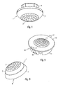
- the illustrated in Figure 1 mushroom-shaped room sensor 1 consists of a Base housing 4 and one arranged on the front side of the base housing 4 conical or dome-shaped head part 2.
- the base housing 4 has an octagonal Form and is designed for mounting within an installation box, such as will be explained later.
- the room sensor 1 shown here is a movement or Presence sensor.
- the head part 2 has a lens arrangement 3 an infrared transparent material, e.g. Plastic on, which serves the detected by the sensor 1 detection area located in the housing 4 in the Imaging sensor element.
- the present invention not only relates on such passive infrared-sensitive sensors (so-called. PIR sensors) but on all types of sensors, for example, instead of the movement or shown here Presence sensor also on brightness sensors or the like.
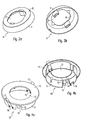
- a surface mounting adapter 6 is provided, the top and Bottom view in Figures 2a and 2b is shown.
- This ring-shaped surface mounting adapter 6 has a frusto-conical circumferential surface 7, which at its Upper edge of an opening 9 having an annular bearing surface. 8 is limited.
- the shape of the opening 9 corresponds to the cross section of the octagonal base housing 4, so that the room sensor 1 from the top of the Surface mounting adapter 6 can be pushed, this then the Base housing 4 includes form-fitting. This results in a forest, as shown in FIG.
- the frustoconical outer side 7 forms the Surface mounting adapter 6 together with the dome-shaped head part 2 the Housing formed from the sensor 1 and the surface mounting adapter 6 Combination.
- the base housing 4 is within the annular surface mounting adapter 6 arranged so that the combination formed in this way a surface mounting can be attached to the wall or ceiling of a room.
- On the surface mounting adapter 6 and the base housing 4 can not - shown - Verrastieri be provided that a solid cohesion allow between the sensor 1 and the surface mounting adapter 6.
- FIGs 4a and 4b show a flush mounting adapter according to the invention 10, which is a so-called flush mounting or the ceiling mounting of the sensor. 1 allows.
- This flush mounting adapter 10 is also annular and has a cylindrical side wall 11 which at its top of a annular surface 12 is limited with a circular opening 13. A connection between the sensor 1 and this flush mount adapter 10 takes place thereby, that the sensor 1 from the bottom in the annular flush mounting adapter 10 is used.
- the circular opening 13 of the annular top 12 is in this case dimensioned that only the lens assembly 3 as the active region of the protruding dome-shaped head part 2.
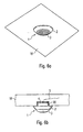
- FIGS. 6a and 6b show firstly the one alone - ie without mounting adapter - Sensor attached to a ceiling 18 of a room 1.
- the installation takes place here Help a arranged in the ceiling 18 installation box 19 - for example this is a Euro can - in which the base housing 4 is inserted and can be attached. As the illustration shows, this is the dome-shaped head part 2 of the sensor 1 on the underside of the ceiling 18 at.
- the Power supply and data line 5 of the sensor 1 extends from the Installation box 19 through the ceiling 18th
- Figures 7a and 7b show the possibility of the sensor 1 by means of a Surface mounting to attach to a ceiling 18 of a room, so at the Outside or bottom. This mounting method is necessary, for example, then if there is no installation box in the ceiling 18.
- the sensor 1 is for this purpose in the manner described above with the surface mounting adapter 6 connected.
- the out of the sensor 1 and the surface mounting adapter 6 formed combination can then on the ceiling by means (not shown) screws, wherein the housing 4 of the sensor 1 now is disposed entirely within the surface mounting adapter 6, so that this fills the distance between the edge region of the head part 2 and the ceiling 18.
- the annular bearing surface 8 of the surface mounting adapter 6 forms the Support surface for the head part 2, the truncated cone-shaped side surface 7 of the Surface mounting adapter 6 forms together with the cover 2 the Overall housing of the sensor mounting adapter combination.
- the height of the side wall 7 of the surface mounting adapter 6 is at least equal high - but preferably slightly higher - as the base housing 4. Accordingly is the case 4 with respect to the surface mounting adapter 6 does not protrude, so that the entire combination can be flush mounted to the underside of the ceiling 18 can.
- the connecting line 5 for the sensor 1 extends through a small within the ceiling 18 located opening, an installation box is for mounting of the sensor 1 is not necessary.
- FIGS. 8a and b show the flush or ceiling installation the formed from the sensor 1 and the flush mounting adapter 10 Combination, especially for mounting in thin suspended Ceilings 19 offers.
- the illustrated examples illustrate that with the help of the two Mounting adapter according to the invention in a simple way the mounting options can be increased for a single sensor. This is not expensive and costly redesign of the sensor housing necessary, rather it is sufficient to use a simple and inexpensive to manufacture adapter.
Description
- Fig. 1
- einen Präsenzsensor in perspektivischer Darstellung, der für sich allein zur Montage in einer Installationsdose vorgesehen ist;
- Fig. 2a und b
- die Ober- und Unterseite eines erfindungsgemäßen Aufputz-Montageadapters;
- Fig. 3
- den mit dem Sensor zusammengesetzten Aufputz-Montageadapter;
- Fig. 4a und b
- die Ober- und Unterseite eines erfindungsgemäßen Unterputz-Montageadapters;
- Fig. 5
- den mit dem Sensor zusammengesetzten Unterputz-Montageadapter;
- Fig. 6a und b
- den in einer ersten Montageweise an einer Decke befestigten Sensor in perspektivischer Darstellung und im Schnitt;
- Fig. 7a und b
- die an einer Decke befestigte Kombination aus dem Sensor und dem Aufputz-Montageadapter in perspektivischer Darstellung und im Schnitt; und
- Fig. 8a und b
- die an einer Decke befestigte Kombination aus dem Sensor und dem Unterputz-Montageadapter in perspektivischer Darstellung und im Schnitt.
Claims (13)
- Pilzartig ausgebildeter Raumsensor (1) mit einem im wesentlichen zylinderförmigen oder eckigen Basisgehäuse (4) sowie einem vor dem Basisgehäuse (4) angeordneten kuppelförmigen Kopfteil (2),
gekennzeichnet durch
einen das Basisgehäuse (4) aufnehmenden Aufputz-Montageadapter (6), welcher den Abstand zwischen dem Randbereich des Kopfteils (2) und der Wand oder Decke (18, 19) eines Raumes ausfüllt. - Raumsensor nach Anspruch 1,
dadurch gekennzeichnet, daß der Aufputz-Montageadapter (6) ringförmig ist. - Raumsensor nach Anspruch 2,
dadurch gekennzeichnet, daß der Aufputz-Montageadapter (6) das Basisgehäuse (4) formschlüssig umfaßt. - Raumsensor nach einem der Ansprüche 1 bis 3,
dadurch gekennzeichnet, daß die Höhe des Montageadapters (6) im wesentlichen der Höhe des Basisgehäuses (4) entspricht. - Raumsensor nach einem der vorherigen Ansprüche,
dadurch gekennzeichnet, daß das Kopfteil (2) eine Linsenanordnung (3) aufweist. - Pilzartig ausgebildeter Raumsensor (1) mit einem im wesentlichen zylinderförmigen oder eckigen Basisgehäuse (4) sowie einem vor dem Basisgehäuse (4) angeordneten kuppelförmigen Kopfteil (2),
gekennzeichnet durch
einen Unterputz-Montageadapter (10), welcher zum Einsetzen in eine Öffnung einer Wand oder Decke (18, 19) eines Raumes bestimmt ist, wobei der Unterputz-Montageadapter (10) den Abstand zwischen dem Öffnungsrand und dem Kopfteil (2) des Raumsensors (1) ausfüllt. - Raumsensor nach Anspruch 6,
dadurch gekennzeichnet, daß der Unterputz-Montageadapter (10) den Abstand zwischen dem Öffnungsrand und einem aktiven Bereich (3) des Kopfteiles (2) ausfüllt. - Raumsensor nach Anspruch 7,
dadurch gekennzeichnet, daß der aktive Bereich eine Linsenanordnung (3) ist. - Raumsensor nach einem der Ansprüche 6 bis 8,
dadurch gekennzeichnet, daß der Unterputz-Montageadapter (10) ringförmig und der Raumsensor (1) von der Rückseite her in den Unterputz-Montageadapter (10) einsetzbar ist. - Raumsensor nach einem der nach Ansprüche 6 bis 9,
dadurch gekennzeichnet, daß der Unterputz-Montageadapter (10) Befestigungsfedern (17) zur Befestigung an einer Raumdecke (19) aufweist. - Raumsensor nach einem der vorherigen Ansprüche,
dadurch gekennzeichnet, daß der Aufputz-Montageadapter (6) oder der Unterputz-Montageadapter (10) Verrastelemente zum Verrasten mit dem Raumsensor (1) aufweisen. - Raumsensor nach einem der vorherigen Ansprüche,
dadurch gekennzeichnet, daß dessen Basisgehäuse (4) in eine in der Wand oder Decke (18, 19) angeordnete Installationsdose (20) einsetzbar ist. - Raumsensor nach einem der vorherigen Ansprüche,
dadurch gekennzeichnet, daß es sich bei dem Raumsensor (1) um einen Anwesenheitssensor handelt.
Applications Claiming Priority (2)
| Application Number | Priority Date | Filing Date | Title |
|---|---|---|---|
| DE10135762 | 2001-07-23 | ||
| DE10135762A DE10135762A1 (de) | 2001-07-23 | 2001-07-23 | Raumsensor mit Montageadapter |
Publications (3)
| Publication Number | Publication Date |
|---|---|
| EP1282092A2 EP1282092A2 (de) | 2003-02-05 |
| EP1282092A3 EP1282092A3 (de) | 2003-05-28 |
| EP1282092B1 true EP1282092B1 (de) | 2005-03-02 |
Family
ID=7692750
Family Applications (1)
| Application Number | Title | Priority Date | Filing Date |
|---|---|---|---|
| EP02016508A Expired - Lifetime EP1282092B1 (de) | 2001-07-23 | 2002-07-23 | Raumsensor mit Montageadapter |
Country Status (4)
| Country | Link |
|---|---|
| EP (1) | EP1282092B1 (de) |
| AT (1) | ATE290244T1 (de) |
| DE (2) | DE10135762A1 (de) |
| ES (1) | ES2236405T3 (de) |
Cited By (4)
| Publication number | Priority date | Publication date | Assignee | Title |
|---|---|---|---|---|
| CN102483224A (zh) * | 2009-02-13 | 2012-05-30 | 路创电子公司 | 用于配置无线传感器的方法和设备 |
| DE102015004458A1 (de) | 2014-06-26 | 2015-12-31 | Elmos Semiconductor Aktiengesellschaft | Vorrichtung und Verfahren für einen klassifizierenden, rauchkammerlosen Luftzustandssensor |
| DE102014019773A1 (de) | 2014-12-17 | 2016-06-23 | Elmos Semiconductor Aktiengesellschaft | Vorrichtung und Verfahren zur Unterscheidung von festen Objekten, Kochdunst und Rauch mittels des Displays eines Mobiltelefons |
| DE102014019172A1 (de) | 2014-12-17 | 2016-06-23 | Elmos Semiconductor Aktiengesellschaft | Vorrichtung und Verfahren zur Unterscheidung von festen Objekten, Kochdunst und Rauch mit einem kompensierenden optischen Messsystem |
Families Citing this family (2)
| Publication number | Priority date | Publication date | Assignee | Title |
|---|---|---|---|---|
| FR2951572B1 (fr) | 2009-10-15 | 2012-04-27 | Hager Controls | Detecteur de mouvements a cache mobile |
| US10429214B2 (en) | 2017-03-07 | 2019-10-01 | Newtonoid Technologies, L.L.C. | Modular elongated wall-mounted sensor system and method |
Family Cites Families (26)
| Publication number | Priority date | Publication date | Assignee | Title |
|---|---|---|---|---|
| DE2920217A1 (de) * | 1979-05-18 | 1980-10-30 | Fuss Fritz Kg | Infrarot-bewegungsmelder |
| US4306230A (en) * | 1979-12-10 | 1981-12-15 | Honeywell Inc. | Self-checking photoelectric smoke detector |
| JPS57123586U (de) * | 1981-01-19 | 1982-08-02 | ||
| DE3447089A1 (de) * | 1984-12-22 | 1986-07-10 | Klaus Maresch | Bewegungsmelder mit wandaufliegend zu befestigendem gehaeuse |
| FR2579802B3 (fr) * | 1985-03-29 | 1988-04-29 | Emile Hugon | Nouveau detecteur optique ponctuel de fumees |
| DE3608393A1 (de) * | 1986-03-13 | 1987-09-17 | Preussag Ag Feuerschutz | Optischer rauchmelder |
| JPS63239592A (ja) * | 1987-03-27 | 1988-10-05 | ホーチキ株式会社 | 光電式煙感知器 |
| DE3710561A1 (de) * | 1987-03-30 | 1988-10-13 | Kopp Gmbh & Co Kg Heinrich | Infrarot-bewegungsmelder |
| DE3710614A1 (de) * | 1987-03-31 | 1988-10-20 | Siedle & Soehne S | Bewegungsmelder |
| DE3735956A1 (de) * | 1987-10-23 | 1989-05-03 | Kopp Gmbh & Co Kg Heinrich | Optisches richtmittel fuer infrarot-bewegungsmelder, punktleuchten u. dgl. |
| DE3900605A1 (de) * | 1989-01-11 | 1990-07-12 | Asea Brown Boveri | Bewegungsmelder |
| DE3910514C2 (de) * | 1989-04-01 | 1998-07-02 | Merten Gmbh & Co Kg Geb | Infrarot-Bewegungsmelder |
| DE4027347A1 (de) * | 1990-08-29 | 1992-03-05 | Hvg Handels Und Warenvermittlu | Aussenleuchte mit integriertem optischen bewegungsmelder |
| DE4137560C1 (de) * | 1991-11-15 | 1993-02-25 | Abb Patent Gmbh, 6800 Mannheim, De | |
| CH685409A5 (de) * | 1993-03-19 | 1995-06-30 | Cerberus Ag | Brandmelder. |
| DE4407497A1 (de) * | 1994-03-07 | 1995-09-14 | Merten Gmbh & Co Kg Geb | Infrarot-Bewegungsmelder |
| DE9403597U1 (de) * | 1994-03-03 | 1994-05-05 | Fritz Poeschel Etg | Einbauteil |
| DE9416314U1 (de) * | 1994-10-10 | 1994-12-01 | Fuss Fritz Gmbh & Co | Rauchmelder |
| DE4445197A1 (de) * | 1994-12-17 | 1996-06-20 | Abb Patent Gmbh | Passiv-Infrarot-Bewegungsmelder mit Sammellinsen zu einer Rundumerfassung von 360 DEG |
| DE29509400U1 (de) * | 1995-06-08 | 1995-09-28 | Gev Gutkes Elektro Vertriebs G | Bewegungsmelderanordnung |
| DE19607872C2 (de) * | 1996-03-01 | 1999-08-12 | Sonlux Licht Und Elektroinstal | Leuchte mit Bewegungsmelder |
| DE29616748U1 (de) * | 1996-09-25 | 1996-11-28 | Kopp Heinrich Ag | Vorrichtung zur Unterputzmontage von tiefbauenden elektrischen Bauteilen und Installationsgeräten |
| DE19639318C1 (de) * | 1996-09-25 | 1997-12-18 | Andreas Toeteberg | Mehrfach-Passiv-Infrarot-(PIR)-Bewegungsmelder |
| DE19648467A1 (de) * | 1996-11-22 | 1998-06-10 | Merten Gmbh & Co Kg Geb | Berührungslos wirkendes Schaltgerät |
| DE29620405U1 (de) * | 1996-11-22 | 1997-06-19 | Merten Gmbh & Co Kg Geb | Bewegungsmelder |
| DE19648466A1 (de) * | 1996-11-22 | 1998-05-28 | Merten Gmbh & Co Kg Geb | Überwachungsgerät |
-
2001
- 2001-07-23 DE DE10135762A patent/DE10135762A1/de not_active Ceased
-
2002
- 2002-07-23 EP EP02016508A patent/EP1282092B1/de not_active Expired - Lifetime
- 2002-07-23 AT AT02016508T patent/ATE290244T1/de active
- 2002-07-23 DE DE50202356T patent/DE50202356D1/de not_active Expired - Lifetime
- 2002-07-23 ES ES02016508T patent/ES2236405T3/es not_active Expired - Lifetime
Cited By (5)
| Publication number | Priority date | Publication date | Assignee | Title |
|---|---|---|---|---|
| CN102483224A (zh) * | 2009-02-13 | 2012-05-30 | 路创电子公司 | 用于配置无线传感器的方法和设备 |
| CN102483224B (zh) * | 2009-02-13 | 2014-04-16 | 路创电子公司 | 用于配置无线传感器的方法和设备 |
| DE102015004458A1 (de) | 2014-06-26 | 2015-12-31 | Elmos Semiconductor Aktiengesellschaft | Vorrichtung und Verfahren für einen klassifizierenden, rauchkammerlosen Luftzustandssensor |
| DE102014019773A1 (de) | 2014-12-17 | 2016-06-23 | Elmos Semiconductor Aktiengesellschaft | Vorrichtung und Verfahren zur Unterscheidung von festen Objekten, Kochdunst und Rauch mittels des Displays eines Mobiltelefons |
| DE102014019172A1 (de) | 2014-12-17 | 2016-06-23 | Elmos Semiconductor Aktiengesellschaft | Vorrichtung und Verfahren zur Unterscheidung von festen Objekten, Kochdunst und Rauch mit einem kompensierenden optischen Messsystem |
Also Published As
| Publication number | Publication date |
|---|---|
| ATE290244T1 (de) | 2005-03-15 |
| DE10135762A1 (de) | 2003-02-13 |
| EP1282092A2 (de) | 2003-02-05 |
| ES2236405T3 (es) | 2005-07-16 |
| DE50202356D1 (de) | 2005-04-07 |
| EP1282092A3 (de) | 2003-05-28 |
Similar Documents
| Publication | Publication Date | Title |
|---|---|---|
| DE2814769C3 (de) | Rauchmeldegerät nach dem Lichtstreuprinzip | |
| DE102019204304A1 (de) | Sicherheitsschalter | |
| EP0566921A1 (de) | Halbleiterbaugruppe, insbesondere Fernsteuer-Empfangsmodul | |
| EP2474987A1 (de) | Einbauschalter | |
| EP1635434A1 (de) | Elektrische/elektronische Installationseinheit | |
| EP1983620A2 (de) | Steckdose mit Orientierungsbeleuchtung | |
| DE69822086T2 (de) | Elektrische Anschlusseinheit mit einem eine verlängerte Seitenwand aufweisenden Verbindungsblock | |
| DE69630147T2 (de) | Dreiteiliges armaturenbrett und verfahren | |
| EP1282092B1 (de) | Raumsensor mit Montageadapter | |
| DE19623708C1 (de) | Lüftungseinrichtung | |
| EP0326942A2 (de) | Infrarot-Sensor | |
| EP3111176B1 (de) | Infrarot-bewegungsmelder | |
| DE60001338T2 (de) | Brandmelder | |
| DE10011615C2 (de) | Station einer Türanlage | |
| EP3627456A1 (de) | Betätigungshandhabe mit zutrittskontrollsystem | |
| EP1477726B1 (de) | LED- Einbauleuchte | |
| EP2650849A2 (de) | Einbau-Passiv-Infrarot-Sensorvorrichtung | |
| EP0234335A2 (de) | Leuchte | |
| CH685409A5 (de) | Brandmelder. | |
| EP1400936B2 (de) | Sicherungs- und Überwachungsvorrichtung für Türen, Fenster oder dergleichen | |
| EP3627457A1 (de) | Zutrittsystem | |
| EP1052748A1 (de) | Bedienungselement zum Befestigen an einer Frontplatte | |
| DE102020109188A1 (de) | Befestigungssystem, Monument und Verfahren zum Anbringen eines Ausstattungsgegenstands an einem Monument | |
| EP0418496B1 (de) | Elektrisches Installationsgerät, insbesondere Schutzkontaktsteckdose | |
| EP3062111A1 (de) | Vorrichtung zur erkennung der präsenz oder bewegung von personen |
Legal Events
| Date | Code | Title | Description |
|---|---|---|---|
| PUAI | Public reference made under article 153(3) epc to a published international application that has entered the european phase |
Free format text: ORIGINAL CODE: 0009012 |
|
| AK | Designated contracting states |
Designated state(s): AT BE BG CH CY CZ DE DK EE ES FI FR GB GR IE IT LI LU MC NL PT SE SK TR |
|
| AX | Request for extension of the european patent |
Extension state: AL LT LV MK RO SI |
|
| PUAL | Search report despatched |
Free format text: ORIGINAL CODE: 0009013 |
|
| AK | Designated contracting states |
Designated state(s): AT BE BG CH CY CZ DE DK EE ES FI FR GB GR IE IT LI LU MC NL PT SE SK TR |
|
| AX | Request for extension of the european patent |
Extension state: AL LT LV MK RO SI |
|
| 17P | Request for examination filed |
Effective date: 20031119 |
|
| AKX | Designation fees paid |
Designated state(s): AT BE BG CH CY CZ DE DK EE ES FI FR GB GR IE IT LI LU MC NL PT SE SK TR |
|
| GRAP | Despatch of communication of intention to grant a patent |
Free format text: ORIGINAL CODE: EPIDOSNIGR1 |
|
| GRAS | Grant fee paid |
Free format text: ORIGINAL CODE: EPIDOSNIGR3 |
|
| GRAA | (expected) grant |
Free format text: ORIGINAL CODE: 0009210 |
|
| AK | Designated contracting states |
Kind code of ref document: B1 Designated state(s): AT BE BG CH CY CZ DE DK EE ES FI FR GB GR IE IT LI LU MC NL PT SE SK TR |
|
| PG25 | Lapsed in a contracting state [announced via postgrant information from national office to epo] |
Ref country code: IE Free format text: LAPSE BECAUSE OF FAILURE TO SUBMIT A TRANSLATION OF THE DESCRIPTION OR TO PAY THE FEE WITHIN THE PRESCRIBED TIME-LIMIT Effective date: 20050302 Ref country code: FI Free format text: LAPSE BECAUSE OF FAILURE TO SUBMIT A TRANSLATION OF THE DESCRIPTION OR TO PAY THE FEE WITHIN THE PRESCRIBED TIME-LIMIT Effective date: 20050302 Ref country code: EE Free format text: LAPSE BECAUSE OF FAILURE TO SUBMIT A TRANSLATION OF THE DESCRIPTION OR TO PAY THE FEE WITHIN THE PRESCRIBED TIME-LIMIT Effective date: 20050302 Ref country code: CZ Free format text: LAPSE BECAUSE OF FAILURE TO SUBMIT A TRANSLATION OF THE DESCRIPTION OR TO PAY THE FEE WITHIN THE PRESCRIBED TIME-LIMIT Effective date: 20050302 Ref country code: TR Free format text: LAPSE BECAUSE OF FAILURE TO SUBMIT A TRANSLATION OF THE DESCRIPTION OR TO PAY THE FEE WITHIN THE PRESCRIBED TIME-LIMIT Effective date: 20050302 Ref country code: SK Free format text: LAPSE BECAUSE OF FAILURE TO SUBMIT A TRANSLATION OF THE DESCRIPTION OR TO PAY THE FEE WITHIN THE PRESCRIBED TIME-LIMIT Effective date: 20050302 |
|
| REG | Reference to a national code |
Ref country code: GB Ref legal event code: FG4D Free format text: NOT ENGLISH |
|
| REG | Reference to a national code |
Ref country code: CH Ref legal event code: NV Representative=s name: A. BRAUN, BRAUN, HERITIER, ESCHMANN AG PATENTANWAE Ref country code: CH Ref legal event code: EP |
|
| RAP2 | Party data changed (patent owner data changed or rights of a patent transferred) |
Owner name: ZUMTOBEL STAFF GMBH |
|
| REG | Reference to a national code |
Ref country code: IE Ref legal event code: FG4D Free format text: GERMAN |
|
| REF | Corresponds to: |
Ref document number: 50202356 Country of ref document: DE Date of ref document: 20050407 Kind code of ref document: P |
|
| NLT2 | Nl: modifications (of names), taken from the european patent patent bulletin |
Owner name: ZUMTOBEL STAFF GMBH |
|
| PG25 | Lapsed in a contracting state [announced via postgrant information from national office to epo] |
Ref country code: GR Free format text: LAPSE BECAUSE OF FAILURE TO SUBMIT A TRANSLATION OF THE DESCRIPTION OR TO PAY THE FEE WITHIN THE PRESCRIBED TIME-LIMIT Effective date: 20050602 Ref country code: BG Free format text: LAPSE BECAUSE OF FAILURE TO SUBMIT A TRANSLATION OF THE DESCRIPTION OR TO PAY THE FEE WITHIN THE PRESCRIBED TIME-LIMIT Effective date: 20050602 Ref country code: DK Free format text: LAPSE BECAUSE OF FAILURE TO SUBMIT A TRANSLATION OF THE DESCRIPTION OR TO PAY THE FEE WITHIN THE PRESCRIBED TIME-LIMIT Effective date: 20050602 |
|
| REG | Reference to a national code |
Ref country code: ES Ref legal event code: FG2A Ref document number: 2236405 Country of ref document: ES Kind code of ref document: T3 |
|
| PG25 | Lapsed in a contracting state [announced via postgrant information from national office to epo] |
Ref country code: CY Free format text: LAPSE BECAUSE OF FAILURE TO SUBMIT A TRANSLATION OF THE DESCRIPTION OR TO PAY THE FEE WITHIN THE PRESCRIBED TIME-LIMIT Effective date: 20050723 Ref country code: LU Free format text: LAPSE BECAUSE OF NON-PAYMENT OF DUE FEES Effective date: 20050723 |
|
| GBT | Gb: translation of ep patent filed (gb section 77(6)(a)/1977) |
Effective date: 20050705 |
|
| PG25 | Lapsed in a contracting state [announced via postgrant information from national office to epo] |
Ref country code: MC Free format text: LAPSE BECAUSE OF NON-PAYMENT OF DUE FEES Effective date: 20050731 |
|
| PG25 | Lapsed in a contracting state [announced via postgrant information from national office to epo] |
Ref country code: PT Free format text: LAPSE BECAUSE OF FAILURE TO SUBMIT A TRANSLATION OF THE DESCRIPTION OR TO PAY THE FEE WITHIN THE PRESCRIBED TIME-LIMIT Effective date: 20050907 |
|
| REG | Reference to a national code |
Ref country code: IE Ref legal event code: FD4D |
|
| PLBE | No opposition filed within time limit |
Free format text: ORIGINAL CODE: 0009261 |
|
| STAA | Information on the status of an ep patent application or granted ep patent |
Free format text: STATUS: NO OPPOSITION FILED WITHIN TIME LIMIT |
|
| ET | Fr: translation filed | ||
| 26N | No opposition filed |
Effective date: 20051205 |
|
| PG25 | Lapsed in a contracting state [announced via postgrant information from national office to epo] |
Ref country code: SE Free format text: LAPSE BECAUSE OF FAILURE TO SUBMIT A TRANSLATION OF THE DESCRIPTION OR TO PAY THE FEE WITHIN THE PRESCRIBED TIME-LIMIT Effective date: 20050602 |
|
| REG | Reference to a national code |
Ref country code: CH Ref legal event code: PFA Owner name: ZUMTOBEL STAFF GMBH Free format text: ZUMTOBEL STAFF GMBH#SCHWEIZERSTRASSE 30#6850 DORNBIRN (AT) -TRANSFER TO- ZUMTOBEL STAFF GMBH#SCHWEIZERSTRASSE 30#6850 DORNBIRN (AT) |
|
| PGFP | Annual fee paid to national office [announced via postgrant information from national office to epo] |
Ref country code: FR Payment date: 20120814 Year of fee payment: 11 Ref country code: BE Payment date: 20120831 Year of fee payment: 11 Ref country code: IT Payment date: 20120725 Year of fee payment: 11 |
|
| PGFP | Annual fee paid to national office [announced via postgrant information from national office to epo] |
Ref country code: NL Payment date: 20120727 Year of fee payment: 11 |
|
| BERE | Be: lapsed |
Owner name: *ZUMTOBEL STAFF G.M.B.H. Effective date: 20130731 |
|
| REG | Reference to a national code |
Ref country code: NL Ref legal event code: V1 Effective date: 20140201 |
|
| REG | Reference to a national code |
Ref country code: FR Ref legal event code: ST Effective date: 20140331 |
|
| PG25 | Lapsed in a contracting state [announced via postgrant information from national office to epo] |
Ref country code: NL Free format text: LAPSE BECAUSE OF NON-PAYMENT OF DUE FEES Effective date: 20140201 Ref country code: BE Free format text: LAPSE BECAUSE OF NON-PAYMENT OF DUE FEES Effective date: 20130731 |
|
| PG25 | Lapsed in a contracting state [announced via postgrant information from national office to epo] |
Ref country code: IT Free format text: LAPSE BECAUSE OF NON-PAYMENT OF DUE FEES Effective date: 20130723 Ref country code: FR Free format text: LAPSE BECAUSE OF NON-PAYMENT OF DUE FEES Effective date: 20130731 |
|
| REG | Reference to a national code |
Ref country code: CH Ref legal event code: PCAR Free format text: NEW ADDRESS: HOLBEINSTRASSE 36-38, 4051 BASEL (CH) |
|
| PGFP | Annual fee paid to national office [announced via postgrant information from national office to epo] |
Ref country code: ES Payment date: 20140825 Year of fee payment: 13 |
|
| REG | Reference to a national code |
Ref country code: ES Ref legal event code: FD2A Effective date: 20170301 |
|
| PG25 | Lapsed in a contracting state [announced via postgrant information from national office to epo] |
Ref country code: ES Free format text: LAPSE BECAUSE OF NON-PAYMENT OF DUE FEES Effective date: 20150724 |
|
| PGFP | Annual fee paid to national office [announced via postgrant information from national office to epo] |
Ref country code: CH Payment date: 20170725 Year of fee payment: 16 |
|
| PGFP | Annual fee paid to national office [announced via postgrant information from national office to epo] |
Ref country code: AT Payment date: 20170727 Year of fee payment: 16 |
|
| PGFP | Annual fee paid to national office [announced via postgrant information from national office to epo] |
Ref country code: GB Payment date: 20180731 Year of fee payment: 17 |
|
| REG | Reference to a national code |
Ref country code: CH Ref legal event code: PL |
|
| REG | Reference to a national code |
Ref country code: AT Ref legal event code: MM01 Ref document number: 290244 Country of ref document: AT Kind code of ref document: T Effective date: 20180723 |
|
| PG25 | Lapsed in a contracting state [announced via postgrant information from national office to epo] |
Ref country code: LI Free format text: LAPSE BECAUSE OF NON-PAYMENT OF DUE FEES Effective date: 20180731 Ref country code: AT Free format text: LAPSE BECAUSE OF NON-PAYMENT OF DUE FEES Effective date: 20180723 Ref country code: CH Free format text: LAPSE BECAUSE OF NON-PAYMENT OF DUE FEES Effective date: 20180731 |
|
| REG | Reference to a national code |
Ref country code: DE Ref legal event code: R084 Ref document number: 50202356 Country of ref document: DE |
|
| PGFP | Annual fee paid to national office [announced via postgrant information from national office to epo] |
Ref country code: DE Payment date: 20190930 Year of fee payment: 18 |
|
| GBPC | Gb: european patent ceased through non-payment of renewal fee |
Effective date: 20190723 |
|
| PG25 | Lapsed in a contracting state [announced via postgrant information from national office to epo] |
Ref country code: GB Free format text: LAPSE BECAUSE OF NON-PAYMENT OF DUE FEES Effective date: 20190723 |
|
| REG | Reference to a national code |
Ref country code: DE Ref legal event code: R119 Ref document number: 50202356 Country of ref document: DE |
|
| PG25 | Lapsed in a contracting state [announced via postgrant information from national office to epo] |
Ref country code: DE Free format text: LAPSE BECAUSE OF NON-PAYMENT OF DUE FEES Effective date: 20210202 |