EP1400936B2 - Sicherungs- und Überwachungsvorrichtung für Türen, Fenster oder dergleichen - Google Patents
Sicherungs- und Überwachungsvorrichtung für Türen, Fenster oder dergleichen Download PDFInfo
- Publication number
- EP1400936B2 EP1400936B2 EP03014819A EP03014819A EP1400936B2 EP 1400936 B2 EP1400936 B2 EP 1400936B2 EP 03014819 A EP03014819 A EP 03014819A EP 03014819 A EP03014819 A EP 03014819A EP 1400936 B2 EP1400936 B2 EP 1400936B2
- Authority
- EP
- European Patent Office
- Prior art keywords
- safety
- monitoring device
- button
- push
- light
- Prior art date
- Legal status (The legal status is an assumption and is not a legal conclusion. Google has not performed a legal analysis and makes no representation as to the accuracy of the status listed.)
- Expired - Lifetime
Links
Images


Classifications
-
- E—FIXED CONSTRUCTIONS
- E05—LOCKS; KEYS; WINDOW OR DOOR FITTINGS; SAFES
- E05B—LOCKS; ACCESSORIES THEREFOR; HANDCUFFS
- E05B65/00—Locks or fastenings for special use
- E05B65/10—Locks or fastenings for special use for panic or emergency doors
- E05B65/108—Electronically controlled emergency exits
-
- G—PHYSICS
- G08—SIGNALLING
- G08B—SIGNALLING SYSTEMS, e.g. PERSONAL CALLING SYSTEMS; ORDER TELEGRAPHS; ALARM SYSTEMS
- G08B13/00—Burglar, theft or intruder alarms
- G08B13/02—Mechanical actuation
- G08B13/08—Mechanical actuation by opening, e.g. of door, of window, of drawer, of shutter, of curtain, of blind
-
- H—ELECTRICITY
- H01—ELECTRIC ELEMENTS
- H01H—ELECTRIC SWITCHES; RELAYS; SELECTORS; EMERGENCY PROTECTIVE DEVICES
- H01H13/00—Switches having rectilinearly-movable operating part or parts adapted for pushing or pulling in one direction only, e.g. push-button switch
- H01H13/02—Details
- H01H13/023—Light-emitting indicators
-
- H—ELECTRICITY
- H01—ELECTRIC ELEMENTS
- H01H—ELECTRIC SWITCHES; RELAYS; SELECTORS; EMERGENCY PROTECTIVE DEVICES
- H01H3/00—Mechanisms for operating contacts
- H01H3/02—Operating parts, i.e. for operating driving mechanism by a mechanical force external to the switch
- H01H3/022—Emergency operating parts, e.g. for stop-switch in dangerous conditions
- H01H2003/0233—Emergency operating parts, e.g. for stop-switch in dangerous conditions for alarm triggering, e.g. fire alarm, emergency off switches operated by breaking a glass
-
- H—ELECTRICITY
- H01—ELECTRIC ELEMENTS
- H01H—ELECTRIC SWITCHES; RELAYS; SELECTORS; EMERGENCY PROTECTIVE DEVICES
- H01H2219/00—Legends
- H01H2219/054—Optical elements
- H01H2219/062—Light conductor
-
- H—ELECTRICITY
- H01—ELECTRIC ELEMENTS
- H01H—ELECTRIC SWITCHES; RELAYS; SELECTORS; EMERGENCY PROTECTIVE DEVICES
- H01H2219/00—Legends
- H01H2219/054—Optical elements
- H01H2219/062—Light conductor
- H01H2219/0622—Light conductor only an illuminated ring around keys
-
- H—ELECTRICITY
- H01—ELECTRIC ELEMENTS
- H01H—ELECTRIC SWITCHES; RELAYS; SELECTORS; EMERGENCY PROTECTIVE DEVICES
- H01H9/00—Details of switching devices, not covered by groups H01H1/00 - H01H7/00
- H01H9/20—Interlocking, locking, or latching mechanisms
- H01H9/28—Interlocking, locking, or latching mechanisms for locking switch parts by a key or equivalent removable member
- H01H9/287—Interlocking, locking, or latching mechanisms for locking switch parts by a key or equivalent removable member wherein the operating part is made inaccessible or more difficult to access by a lid, cover or guard, e.g. lockable covers
Definitions
- the invention relates to a security and monitoring device for doors, windows or the like, for flush mounting or Aufputzeinbau, with a housing in which a safety button or emergency button is arranged.
- Such a security and monitoring device is for example from the DE 199 34 482 C2 known.
- a safety button In a stationary mounted in the door area housing is a safety button, with in one
- Hazard case a door, a window or the like can be unlocked and opened.
- this backup and monitoring device only one circuit board is arranged, so that it is not possible to integrate additional functions in the security and monitoring device, such.
- three boards are arranged in the housing, so that several functions can be realized simultaneously.
- the boards are arranged parallel to each other and at a distance from each other.
- a particularly favorable installation arrangement results when, according to an advantageous development of the safety button with one of the boards electrically and simultaneously mechanically connected.
- one of the boards preferably the front board, connected to a lighting device surrounding the safety button.
- the illumination device consists of a light-conducting material, in particular a light-conducting plastic. In this way it can be ensured that the illumination device on the one hand has sufficient luminosity and that on the other hand no direct contact with a light source is required upon contact by a person.
- the safety button is circular and that the illumination device surrounds the safety button in an annular manner.
- a gap is preferably formed, so that an easy operation of the safety button can be done without the safety button is obstructed by the lighting device.
- At least one light-emitting diode is provided on one of the circuit boards, which serves as a light source for the illumination device.
- a light-emitting diode consumes little energy, but can still provide a sufficient amount of light for the lighting device available.
- the arrangement of the light emitting diode on the board is further ensured that no electrical energy for the lighting device from the backup and monitoring device needs to be led out, so that a contact of live parts can be avoided with certainty.
- a plurality of light-emitting diodes or other light sources may be provided and serve as lighting means for the illumination device.
- the lighting device z. B an annular plastic part of a photoconductive material, wherein the one end face of the annular plastic part protrudes from a mounting plate and surrounds the likewise protruding button operation of the safety button. Due to the annular configuration of the plastic part, a good adaptation to the circular safety button is achieved and the projection on the mounting plate ensures good visibility from all sides of the lighting device.
- the other end face of the annular plastic part is arranged behind the mounting plate in front of a circuit board and communicates with the light-emitting diodes in connection and lies in particular to them.
- recesses may also be located within the illumination device in the area of the light sources into which the light sources completely or partially submerge. As a result of this configuration is a good light pipe from the LEDs to the outside of the backup and monitoring device lying area of the lighting device ensured.
- the illumination device In order for the illumination device to emit a light which is easily visible from afar, provision is made according to a preferred embodiment for the light-emitting diodes to emit a bright or white light.
- the illumination device is preferably substantially conical and lies with its larger diameter in the region of the light-emitting diodes.
- one of the boards preferably the rear board, serves for the power supply, for the general control and / or for the connection of several safety and monitoring devices with one another.
- all the functions required for the functioning of the security and monitoring device boards can be taken over from a single board.
- connection of several security and monitoring devices preferably takes place via a BUS system.
- the design of the safety and monitoring device is designed to be applicable to a variety of applications. So the dimensional adjustment is suitable to be used in a commercial switch box flush-mounted; Furthermore, of course, the same device can be used to be used in a surface-mounted application in a suitable housing.
- the safety and monitoring device always contains all components in order to realize a self-sufficient operation.
- the device is also designed so that it is covered by a frame into which a flap covering the safety button is inserted. This ensures on the one hand that there can be no accidental release of the safety button and on the other hand prevents the sunken, thickened parts of the safety and monitoring device can be influenced or manipulated from the outside, since all these parts are covered by the frame.
- This construction applies both in a wall mounted safety and monitoring device as well as in the "surface-mounted version", d. H. in a suitable housing, the device is housed. Due to the ingenious design a realization with the same components is possible without modification in all applications.
- a sabotage switch is provided in the device according to a preferred embodiment, which switches upon removal of the frame and / or the flap and triggers an alarm device, for example.
- the sabotage switch is preferably designed as a microswitch, so that it occupies as little space as possible in the structure of the safety and monitoring device.
- a pin is mounted on the flap, which acts on the sabotage switch with attached flap and / or attached frame. As soon as the flap and / or the frame are removed, the pin changes its position and triggers a switching operation of the sabotage switch.
- a transparent disc is arranged, which is offset upon actuation of the safety button and can then be reset, d. H. the disc is not destroyed when an alarm is triggered.
- the device can be used with all boards in a standard flush-mounted box.
- This has the advantage that the security and monitoring device according to the invention can be installed in standard flush-mounted boxes, so that no special designs are required. Furthermore, such a combination with other installation equipment, such as switches, sockets, etc., possible.
- the cover is realized with the already described above common frame. Nevertheless, the frame is a commercially available cover frame for flush-mounted installation devices. At the same time this frame is protected in the way of the invention against removal via the sabotage switch described above with the cover of the safety button.
- the backup and monitoring device according to the invention can also be used in wet areas, the entire device is formed at least water-protected according to an advantageous development.
- a securing and monitoring device 1 according to the invention is a flush-mounted model in the FIG. 1 designed and fits in a (not shown here) standard switch box.
- the security and monitoring device 1 has a structure 2, which is located in the installed state within a wall.
- the structure 2 may consist of a board 6 or more boards 7, 8.
- the outer end forms a mounting plate 14.
- This mounting plate 14 is designed so that it is also suitable for mounting in installation flush boxes and on-wall housings.
- the security and monitoring device 1 is provided with a safety button 3.
- the safety button 3 is circular and projects beyond the mounting plate 14. It can be pressed to allow an emergency operation of a door, a window or the like.
- the safety button 3 is with its electrical connections 15 z. B. on the board 7 ( FIG. 2 ) connected.
- the mechanical attachment takes place either on the same board 7 or as shown in the embodiment, by means of a nut 16 on the board 6.
- the safety button 3 is an integral part of the structure 2.
- a display 17 either indicates the operational safety button 3 or its operation.
- a display 17 a light source or a mechanical display can be used.
- the safety button 3 is surrounded by a lighting device 4, which surrounds the safety button 3 annular game.
- the lighting device 4 consists of a substantially conical plastic ring made of a light-conducting material.
- the plastic ring protrudes with its smaller diameter over the mounting plate 14, but not as far as the safety button 3 (see. Figures 2 and 3 ). With its larger diameter of the plastic ring is within the structure 2 of light emitting diodes 5, which serve as a light source for the illumination device 4.
- the output from the LEDs 5 light which is preferably light or white, enters the rear end face of the plastic ring, is forwarded by the photoconductive material of the plastic ring and exits from the mounting plate 14 projecting end of the illumination device 4, so that light can be well recognized from the outside.
- indentations 18 can be located in the illumination device 4, in which wholly or partially the light-emitting diodes 5 dip.
- the securing and monitoring device 1 When installed, the securing and monitoring device 1 is covered by a frame 9.
- a flap 10 is arranged, which surrounds the safety button 3.
- a (not shown) glass plate is further stored, which is displaced to the rear on actuation of the safety button 3 and then can be put back to their original position without the disc is destroyed.
- a tamper switch 11 is provided, which is preferably designed as a microswitch. Upon removal of the flap 10, the tamper switch 11 triggers a switching process, so that z. B. an acoustic signal is generated.
- a pin 12 is arranged on the flap 10, which presses on the sabotage switch 11 (see. FIG. 5 ) and the sabotage switch 11 keeps closed. Once the flap 10 is removed, the pin 12 is removed with. Thus, the pressure of the pin 12 on the sabotage switch 11 and a z. B. spring-loaded switching element 13 (see. FIG. 2 ) raises and thereby triggers the switching process.
- the entire device is preferably designed to be watertight.
Landscapes
- Business, Economics & Management (AREA)
- Emergency Management (AREA)
- Physics & Mathematics (AREA)
- General Physics & Mathematics (AREA)
- Burglar Alarm Systems (AREA)
- Alarm Systems (AREA)
- Switch Cases, Indication, And Locking (AREA)
- Push-Button Switches (AREA)
Description
- Die Erfindung betrifft eine Sicherungs- und Überwachungsvorrichtung für Türen, Fenster oder dergleichen, für den Unterputzeinbau oder Aufputzeinbau, mit einem Gehäuse, in dem ein Sicherheitstaster bzw. Nottaster angeordnet ist.
- Eine solche Sicherungs- und Überwachungsvorrichtung ist beispielsweise aus der
DE 199 34 482 C2 bekannt. In einem ortsfest im Türbereich angebrachten Gehäuse befindet sich ein Sicherheitstaster, mit dem in einem - Gefahrenfall eine Tür, ein Fenster oder dergleichen entriegelt und geöffnet werden kann. In dieser Sicherungs- und Überwachungsvorrichtung ist jedoch nur eine Platine angeordnet, so dass es nicht möglich ist, zusätzliche Funktionen in die Sicherungs- und Überwachungsvorrichtung zu integrieren, wie z. B. eine Beleuchtungsmöglichkeit für den Sicherheitstaster oder eine Verknüpfung mit anderen Sicherungs- und Überwachungsvorrichtungen.
- Es ist daher Aufgabe der vorliegenden Erfindung, eine Sicherungs- und Überwachungsvorrichtung der eingangs erläuterten Art zu schaffen, bei der zusätzliche Funktionen in die Sicherungs- und Überwachungsvorrichtung integriert werden können und die geeignet ist, für unterschiedliche Einbausituationen Verwendung zu finden.
- Diese Aufgabe wird durch die im Patentanspruch 1 angegebenen Merkmale gelöst. Vorteilhafte Weiterbildungen ergeben sich aus den Unteransprüchen.
- Dadurch, dass in dem Gehäuse der Sicherungs- und Überwachungsvorrichtung mindestens eine Platine mit unterschiedlichen Funktionselementen vorgesehen ist, ist es möglich, weitere Funktionen in die Sicherungsund Überwachungsvorrichtung zu integrieren, so dass z. B. eine Beleuchtungsmöglichkeit für den Sicherheitstaster oder eine Verknüpfung mit anderen Sicherungs- und Überwachungsvorrichtungen realisiert werden kann. Ferner ist eine Verknüpfung mit einem BUS-System und die Integration einer Stromversorgung möglich.
- Gemäß einer vorteilhaften Weiterbildung sind drei Platinen in dem Gehäuse angeordnet, so dass mehrere Funktionen gleichzeitig realisiert werden können.
- Damit alle Platinen möglichst platzsparend untergebracht werden können, ist gemäß einer bevorzugten Ausgestaltung vorgesehen, dass die Platinen parallel zueinander und mit Abstand voneinander angeordnet sind.
- Eine besonders günstige Einbauanordnung ergibt sich, wenn nach einer vorteilhaften Weiterbildung der Sicherheitstaster mit einer der Platinen elektrisch und gleichzeitig mechanisch verbunden wird.
- Um eine gute Erkennbarkeit des Sicherheitstasters auch bei schlechten Sichtverhältnissen zu gewährleisten, ist nach einer vorzugsweisen Ausführungsform eine der Platinen, vorzugsweise die vordere Platine, mit einer Beleuchtungseinrichtung verbunden, welche den Sicherheitstaster umgibt.
- Gemäß einer bevorzugten Weiterbildung ist vorgesehen, dass die Beleuchtungseinrichtung aus einem lichtleitenden Material, insbesondere einem lichtleitenden Kunststoff besteht. Hierdurch kann sichergestellt werden, dass die Beleuchtungseinrichtung einerseits eine ausreichende Leuchtkraft besitzt und dass andererseits bei einer Berührung durch eine Person kein direkter Kontakt mit einer Lichtquelle erforderlich ist.
- Damit die Lage des Sicherheitstasters präzise markiert wird, ist gemäß einer vorteilhaften Ausgestaltung vorgesehen, dass der Sicherheitstaster kreisförmig ausgebildet ist und dass die Beleuchtungseinrichtung den Sicherheitstaster ringförmig umgibt.
- Zwischen dem Sicherheitstaster und der Beleuchtungseinrichtung ist vorzugsweise ein Spalt gebildet, damit eine leichte Betätigung des Sicherheitstasters erfolgen kann, ohne dass der Sicherheitstaster durch die Beleuchtungseinrichtung behindert wird.
- Um die Beleuchtungseinrichtung mit Licht zu versorgen, ist nach einer bevorzugten Ausführungsform auf einer der Platinen mindestens eine Leuchtdiode vorgesehen, welche als Lichtquelle für die Beleuchtungseinrichtung dient. Eine solche Leuchtdiode verbraucht wenig Energie, kann aber trotzdem eine ausreichende Lichtmenge für die Beleuchtungseinrichtung zur Verfügung stellen. Durch die Anordnung der Leuchtdiode auf der Platine wird weiterhin gewährleistet, dass keine elektrische Energie für die Beleuchtungseinrichtung aus der Sicherungs- und Überwachungsvorrichtung herausgeführt zu werden braucht, so dass eine Berührung von stromführenden Teilen mit Sicherheit vermieden werden kann. Je nach Bedarf können auch mehrere Leuchtdioden oder andere Lichtquellen vorgesehen sein und als Leuchtmittel für die Beleuchtungseinrichtung dienen.
- Nach einer vorteilhaften Weiterbildung ist die Beleuchtungseinrichtung z. B. ein ringförmiges Kunststoffteil aus einem lichtleitenden Material, wobei die eine Stirnseite des ringförmigen Kunststoffteiles aus einer Montageplatte hervorsteht und den ebenfalls vorstehenden Betätigungsknopf des Sicherheitstasters umgibt. Durch die ringförmige Ausgestaltung des Kunststoffteiles wird eine gute Anpassung an den kreisförmigen Sicherheitstaster erreicht und das Vorstehen über die Montageplatte gewährleistet eine von allen Seiten gute Sichtbarkeit der Beleuchtungseinrichtung.
- Vorzugsweise ist die andere Stirnseite des ringförmigen Kunststoffteiles hinter der Montageplatte vor einer Platine angeordnet und steht mit den Leuchtdioden in Verbindung und liegt insbesondere an ihnen an. Zur Verbesserung der Lichtausbeute können sich auch innerhalb der Beleuchtungseinrichtung im Bereich der Lichtquellen Einbuchtungen befinden, in die die Lichtquellen ganz oder teilweise eintauchen. Infolge dieser Ausgestaltung ist eine gute Lichtleitung von den Leuchtdioden zu dem außerhalb der Sicherungs- und Überwachungsvorrichtung liegenden Bereich der Beleuchtungseinrichtung sichergestellt.
- Damit in einem Gefahrenfall eine gute Erreichbarkeit und Betätigung des Sicherheitstasters auch unter ungünstigen Bedingungen gewährleistet ist, steht nach einer vorteilhaften Weiterbildung der Sicherheitstaster weiter von der Montageplatte vor als die Beleuchtungseinrichtung. Somit wird eine Betätigung des Sicherheitstasters nicht durch die Beleuchtungseinrichtung behindert.
- Damit die Beleuchtungseinrichtung ein gut und weithin sichtbares Licht abgibt, ist gemäß einer bevorzugten Weiterbildung vorgesehen, dass die Leuchtdioden ein helles oder weißes Licht ausstrahlen.
- Die Beleuchtungseinrichtung ist vorzugsweise im Wesentlichen konisch ausgebildet und liegt mit ihrem größeren Durchmesser im Bereich der Leuchtdioden.
- Gemäß einer vorteilhaften Weiterbildung ist vorgesehen, dass eine der Platinen, vorzugsweise die hintere Platine, zur Stromversorgung, zur allgemeinen Steuerung und/oder zur Verbindung mehrerer Sicherungs- und Überwachungsvorrichtungen untereinander dient. Somit können alle Funktionen, die zur Funktion der Sicherungs- und Überwachungsvorrichtung Platinen erforderlich sind, von einer einzigen Platine übernommen werden.
- Dies ermöglicht einen relativ geringen Raumbedarf der erfindungsgemäßen Sicherungs- und Überwachungsvorrichtung.
- Um eine möglichst einfache, aber trotzdem sichere Verbindung und einen reibungslosen Datenaustausch zwischen mehreren Sicherungs- und Überwachungsvorrichtungen ermöglichen zu können, erfolgt die Verbindung mehrerer Sicherungs- und Überwachungsvorrichtungen vorzugsweise über ein BUS-System.
- Der Aufbau der Sicherungs- und Überwachungsvorrichtung ist so konzipiert, dass er für verschiedene Anwendungsbereiche anwendbar ist. So ist die maßliche Abstimmung geeignet, in eine handelsübliche Schalterdose Unterputz eingesetzt zu werden; ferner kann natürlich auch die gleiche Vorrichtung dazu verwendet werden, um in einer Aufputzanwendung in einem geeigneten Gehäuse eingesetzt zu werden. Stets beinhaltet die Sicherungs- und Überwachungsvorrichtung alle Komponenten, um einen autarken Betrieb zu realisieren. So ist die Vorrichtung auch dahingehend ausgelegt, dass sie von einem Rahmen abgedeckt ist, in den eine den Sicherheitstaster abdeckende Klappe eingesetzt ist. Hierdurch wird einerseits sichergestellt, dass es nicht zu einer unbeabsichtigten Auslösung des Sicherheitstasters kommen kann und andererseits verhindert, dass die versenkt liegenden, abgedickten Teile der Sicherungs- und Überwachungsvorrichtung von außen beeinflusst oder manipuliert werden können, da all diese Teile von dem Rahmen verdeckt sind. Dieser Aufbau gilt sowohl bei in einer Wand eingelassenen Sicherungs- und Überwachungsvorrichtung als auch in der "Aufputz-Version", d. h. in einem geeigneten Gehäuse ist die Vorrichtung untergebracht. Durch die geniale Konstruktion ist ohne Änderung bei allen Anwendungsfällen eine Realisierung mit den gleichen Bauteilen möglich.
- Um eine Manipulation an dem Rahmen und/oder der Klappe sofort erkennen zu können, ist nach einer bevorzugten Ausführungsform in der Vorrichtung ein Sabotageschalter vorgesehen, der bei Entfernung des Rahmens und/oder der Klappe schaltet und beispielsweise eine Alarmvorrichtung auslöst.
- Der Sabotageschalter ist vorzugsweise als Mikroschalter ausgebildet, so dass er in dem Aufbau der Sicherungs- und Überwachungsvorrichtung möglichst wenig Raum einnimmt.
- Damit bei einer Manipulation an dem Rahmen und/oder der Klappe oder einem Entfernen dieser Teile der Sabotageschalter ausgelöst werden kann, ist erfindungsgemäss an der Klappe ein Stift gelagert, der bei aufgesetzter Klappe und/oder aufgesetztem Rahmen den Sabotageschalter beaufschlagt. Sobald die Klappe und/oder der Rahmen entfernt werden, verändert der Stift seine Lage und löst damit einen Schaltvorgang des Sabotageschalters aus.
- Damit einerseits eine gute Sichtbarkeit des Sicherheitstasters gegeben ist, andererseits aber auch ein gewisser Schutz gegen unbeabsichtigtes Berühren des Sicherheitstasters vorhanden ist, ist gemäß einer vorteilhaften Ausgestaltung vorgesehen, dass in der Klappe eine durchsichtige Scheibe angeordnet ist, die bei einer Betätigung des Sicherheitstasters versetzt wird und sich anschließend zurücksetzen lässt, d. h. die Scheibe wird beim Auslösen eines Alarmes nicht zerstört.
- Besonders vorteilhaft ist es, dass nach einer weiteren Ausführungsform die Vorrichtung mit allen Platinen in eine Standard-Unterputzdose einsetzbar ist. Dies hat den Vorteil, dass die erfindungsgemäße Sicherungs- und Überwachungsvorrichtung in handelsübliche Unterputzdosen eingebaut werden kann, so dass keine Sonderanfertigungen erforderlich sind. Ferner ist so eine Kombination mit anderen Installationseinrichtungen, wie Schalter, Steckdosen usw., möglich. Die Abdeckung wird mit dem bereits vorbeschriebenen gemeinsamen Rahmen realisiert. Bei dem Rahmen handelt es sich gleichwohl um einen handelsüblichen Abdeckrahmen für Unterputzinstallationsgeräte. Gleichzeitig ist dieser Rahmen im Wege der Erfindung gegen ein Entfernen über den vorbeschriebenen Sabotageschalter mit der Abdeckkappe des Sicherheitstasters geschützt.
- Damit die erfindungsgemäße Sicherungs- und Überwachungsvorrichtung auch in Nassräumen eingesetzt werden kann, ist nach einer vorteilhaften Weiterbildung die gesamte Vorrichtung zumindest wassergeschützt ausgebildet.
- Weitere Merkmale und Vorteile der Erfindung ergeben sich aus der nachfolgenden Beschreibung eines bevorzugten Ausführungsbeispieles.
- Es zeigen:
- Figur 1:
- Eine perspektivische Ansicht der erfindungsgemäßen Sicherungs- und Überwachungsvorrichtung,
- Figur 2:
- eine Seitenansicht der erfindungsgemäßen Sicherungs- und Überwachungsvorrichtung,
- Figur 3:
- einen Querschnitt durch die erfindungsgemäße Sicherungsund Überwachungsvorrichtung,
- Figur 4:
- eine weitere perspektivische Ansicht der erfindungsgemäßen Sicherungs- und Überwachungsvorrichtung und
- Figur 5;
- eine weitere Seitenansicht der erfindungsgemäßen Sicherungs- und Überwachungsvorrichtung.
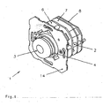
- Eine erfindungsgemäße Sicherungs- und Überwachungsvorrichtung 1 ist als Unterputzmodell in der
Figur 1 ausgebildet und passt in eine (hier nicht dargestellte) Standardschalterdose. Die Sicherungs- und Überwachungsvorrichtung 1 weist einen Aufbau 2 auf, der sich im eingebauten Zustand innerhalb einer Wand befindet. Der Aufbau 2 kann aus einer Platine 6 oder mehreren Platinen 7, 8 bestehen. Den äußeren Abschluss bildet dabei eine Montageplatte 14. Diese Montageplatte 14 ist so ausgelegt, dass sie gleichzeitig zur Befestigung in Installationsunterputzdosen als auch an Aufputzgehäusen geeignet ist. - Die Sicherungs- und Überwachungsvorrichtung 1 ist mit einem Sicherheitstaster 3 versehen. Der Sicherheitstaster 3 ist kreisförmig ausgebildet und steht über der Montageplatte 14 vor. Er kann gedrückt werden, um eine Notfall-Betätigung einer Tür, eines Fensters oder dergleichen zu ermöglichen.
- Der Sicherheitstaster 3 ist mit seinen elektrischen Anschlüssen 15 z. B. an der Platine 7 (
Figur 2 ) angeschlossen. Die mechanische Befestigung erfolgt entweder an der gleichen Platine 7 oder wie in dem Ausführungsbeispiel gezeigt, mittels einer Mutter 16 an der Platine 6. Somit ist der Sicherheitstaster 3 integraler Bestandteil des Aufbaues 2. In dem Sicherheitstaster 3 befindet sich ferner eine Anzeige 17, die entweder den betriebsbereiten Sicherheitstaster 3 oder seine Betätigung anzeigt. Als Anzeige 17 kann ein Leuchtmittel oder eine mechanische Anzeige verwendet werden. - Der Sicherheitstaster 3 ist von einer Beleuchtungseinrichtung 4 umgeben, die den Sicherheitstaster 3 ringförmig mit Spiel umgibt. Die Beleuchtungseinrichtung 4 besteht aus einem im Wesentlichen konischen Kunststoffring aus einem lichtleitenden Material. Der Kunststoffring steht mit seinem kleineren Durchmesser über der Montageplatte 14 vor, aber nicht so weit wie der Sicherheitstaster 3 (vgl.
Figuren 2 und3 ). Mit seinem größeren Durchmesser liegt der Kunststoffring innerhalb des Aufbaues 2 an Leuchtdioden 5 an, die als Lichtquelle für die Beleuchtungseinrichtung 4 dienen. Das von den Leuchtdioden 5 abgegebene Licht, das vorzugsweise hell oder weiß ist, tritt in die hintere Stirnfläche des Kunststoffringes ein, wird von dem lichtleitenden Material des Kunststoffringes weitergeleitet und tritt aus dem aus der Montageplatte 14 vorstehenden Ende der Beleuchtungseinrichtung 4 aus, so dass Licht gut von außen erkannt werden kann. Zur besseren Lichtausbeute können sich in der Beleuchtungseinrichtung 4 Einbuchtungen 18 befinden, in die ganz oder teilweise die Leuchtdioden 5 eintauchen. - In dem im eingebauten Zustand unter Putz liegenden Aufbau 2 der Sicherungs- und Überwachungsvorrichtung 1 sind im dargestellten Ausführungsbeispiel drei Platinen 6, 7, 8 untergebracht, die in parallelen Ebenen zueinander und mit Abstand voneinander angeordnet sind. Dabei ist die Anordnung so getroffen, dass die mittlere Platine 7 mit dem Sicherheitstaster 3 verbunden ist, während die vordere Platine 6 die Leuchtdioden 5 für die Beleuchtungseinrichtung 4 kontaktiert. Auf der hinteren Platine 8 sind allgemeine Versorgungseinrichtungen, wie z. B. die Stromversorgung, Steuerungseinrichtungen oder Anschlüsse zur Verknüpfung mit anderen Sicherungs- und Überwachungseinrichtungen, z. B. über BUS-Leitungen, untergebracht.
- Im eingebauten Zustand ist die Sicherungs- und Überwachungsvorrichtung 1 von einem Rahmen 9 abgedeckt. In diesem Rahmen 9 ist eine Klappe 10 angeordnet, welche den Sicherheitstaster 3 umgibt. In der Klappe 10 ist weiterhin eine (nicht dargestellte) Glasscheibe gelagert, die bei einer Betätigung des Sicherheitstasters 3 nach hinten verschoben wird und die sich anschließend wieder in ihre Ausgangslage zurückversetzen lässt, ohne dass die Scheibe zerstört wird.
- Um zu verhindern, dass an der Klappe 10 und/oder an dem Rahmen 9, z. B. aus Sabotagegründen, Manipulationen vorgenommen werden können, ist in dem Aufbau 2 der Sicherungs- und Überwachungsvorrichtung 1 ein Sabotageschalter 11 vorgesehen, der vorzugsweise als Mikroschalter ausgebildet ist. Bei Entfernung der Klappe 10 löst der Sabotageschalter 11 einen Schaltvorgang aus, so dass z. B. ein akustisches Signal erzeugt wird. Dazu ist an der Klappe 10 ein Stift 12 angeordnet, der auf den Sabotageschalter 11 drückt (vgl.
Figur 5 ) und den Sabotageschalter 11 geschlossen hält. Sobald die Klappe 10 entfernt wird, wird der Stift 12 mit entfernt. Somit fehlt der Druck des Stiftes 12 auf den Sabotageschalter 11 und ein z. B. federbelastetes Schaltglied 13 (vgl.Figur 2 ) stellt sich auf und löst dadurch den Schaltvorgang aus. - Um zu verhindern, dass die Sicherungs- und Überwachungsvorrichtung 1 beim Einsatz in Nassräumen Beschädigungen erfährt, ist die gesamte Vorrichtung vorzugsweise wasserdicht ausgebildet.
- Die vorhergehende Beschreibung des Ausführungsbeispieles der vorliegenden Erfindung dient nur zu illustrativen Zwecken und nicht zum Zwekke der Beschränkung der Erfindung. Im Rahmen der Erfindung sind verschiedene Änderungen und Modifikationen möglich, ohne den Umfang der Erfindung sowie ihrer Äquivalente zu verlassen.
-
- 1
- Sicherungs- und Überwachungsvorrichtung
- 2
- Aufbau
- 3
- Sicherheitstaster
- 4
- Beleuchtungseinrichtung
- 5
- Leuchtdiode
- 6
- Platine
- 7
- Platine
- 8
- Platine
- 9
- Rahmen
- 10
- Klappe
- 11
- Sabotageschalter
- 12
- Stift
- 13
- Schaltglied
- 14
- Montageplatte
- 15
- elektrische Anschlüsse
- 16
- Mutter
- 17
- Anzeige
- 18
- Einbuchtungen
Claims (20)
- Sicherungs- und Überwachungsvorrichtung- mit einem Aufbau (2), der die notwendigen Bauteile vorzugsweise auf mindestens einer Platine (6, 7, 8) enthält;- mit einem Sicherheitstaster (3);- mit einer Beleuchtungseinrichtung (4), die den Sicherheitstaster (3) umschließt;- mit einer verschwenkbaren Abdeckung; und- mit einem Sabotascheschalter (11) im Aufbau (2)- wobei die Sicherungs- und Überwachungsvorrichtung (1) zur Befestigung eine Montageplatte (14) aufweist, die einerseits von einem Betätigungsknopf des Sicherheitstasters (3) und der Beleuchtungseinrichtung (4) durchbrochen wird, und- wobei die Montageplatte (14) im Montagezustand von einem Abdeckrahmen (9) überdeckt wird,
dadurch gekennzeichnet,- dass in dem Abdeckrahmen eine den Sicherheitstaster (3) abdeckende Klappe (10) eingesetzt ist,- wobei der Sabotageschalter (11) bei Entfernung der Klappe (10) schaltet und beispielsweise eine Alarmvorrichtung auslöst, und- dass an der Klappe (10) ein Stift (12) gelagert ist, der bei geschlossener Klappe (10) und aufgesetztem Abdeckrahmen (9) den Sabotageschalter (11) beaufschlagt. - Sicherungs- und Überwachungsvorrichtung nach Anspruch 1, dadurch gekennzeichnet, dass der Sicherheitstaster (3) mit mindestens einer der Platinen (6, 7, 8) des Aufbaues (2) elektrisch und/oder mechanisch verbunden ist.
- Sicherungs- und Überwachungsvorrichtung nach einem der vorhergehenden Ansprüche, dadurch gekennzeichnet, dass der Sicherheitstaster (3) eine Anzeige, vorzugsweise eine elektrische Anzeige, enthält.
- Sicherungs- und Überwachungsvorrichtung nach einem der vorhergehenden Ansprüche, dadurch gekennzeichnet, dass eine der Platinen, vorzugsweise die vordere Platine (6), mit der Beleuchtungseinrichtung (4) verbunden ist.
- Sicherungs- und Überwachungsvorrichtung nach Anspruch 1, dadurch gekennzeichnet, dass die Beleuchtungseinrichtung (4) aus einem lichtleitenden Material, insbesondere einem lichtleitenden Kunststoff, besteht.
- Sicherungs- und Überwachungsvorrichtung nach einem der vorhergehenden Ansprüche, dadurch gekennzeichnet, dass der Sicherheitstaster (3) kreisförmig ausgebildet ist und dass die Beleuchtungseinrichtung (4) den Sicherheitstaster (3) ringförmig umgibt.
- Sicherungs- und Überwachungsvorrichtung nach einem der vorhergehenden Ansprüche, dadurch gekennzeichnet, dass zwischen dem Sicherheitstaster (3) und der Beleuchtungseinrichtung (4) ein Spalt gebildet ist.
- Sicherungs- und Überwachungsvorrichtung nach einem der vorhergehenden Ansprüche, dadurch gekennzeichnet, -dass in dem Aufbau (2) mindestens eine Leuchtdiode (5) vorgesehen ist, welche als Lichtquelle für die Beleuchtungseinrichtung (4) dient.
- Sicherungs- und Überwachungsvorrichtung nach einem der vorhergehenden Ansprüche, dadurch gekennzeichnet, dass die andere Stirnseite des ringförmigen Kunststoffteiles innerhalb des Aufbaues (2) angeordnet ist und mit den Leuchtdioden (5) in Verbindung steht, insbesondere an ihnen anliegt bzw. die Leuchtdioden (5) in Einbuchtungen (18) eintauchen.
- Sicherungs- und Überwachungsvorrichtung nach einem der vorhergehenden Ansprüche, dadurch gekennzeichnet, dass der Sicherheitstaster (3) weiter aus der Montageplatte (14) vorsteht als die Beleuchtungseinrichtung (4).
- Sicherungs- und Überwachungsvorrichtung nach einem der vorhergehenden Ansprüche, dadurch gekennzeichnet, dass die Leuchtdioden (5) ein helles oder weißes Licht ausstrahlen.
- Sicherungs- und Überwachungsvorrichtung nach einem der vorhergehenden Ansprüche, dadurch gekennzeichnet, dass die Beleuchtungseinrichtung (4) im Wesentlichen konisch ausgebildet ist und mit ihrem größeren Durchmesser an den Leuchtdioden (5) anliegt.
- Sicherungs- und Überwachungsvorrichtung nach einem der vorhergehenden Ansprüche, dadurch gekennzeichnet, dass die Platinen (6, 7, 8) parallel zueinander und mit Abstand voneinander angeordnet sind.
- Sicherungs- und Überwachungsvorrichtung nach einem der vorhergehenden Ansprüche, dadurch gekennzeichnet, dass eine der Platinen, vorzugsweise die hintere Platine (8), zur Stromversorgung, zur allgemeinen Steuerung und/oder zur Verbindung mehrerer Sicherungs- und Überwachungsvorrichtungen untereinander dient.
- Sicherungs- und Überwachungsvorrichtung nach einem der vorhergehenden Ansprüche, dadurch gekennzeichnet, dass die Verbindung mehrerer Sicherungs- und Überwachungsvorrichtungen untereinander über eine BUS-Leitung erfolgt.
- Sicherungs- und Überwachungsvorrichtung nach einem der vorhergehenden Ansprüche, dadurch gekennzeichnet, dass der Sabotageschalter (11) als Mikroschalter ausgebildet ist.
- Sicherungs- und Überwachungsvorrichtung nach einem der vorhergehenden Ansprüche, dadurch gekennzeichnet, dass in der Klappe (10) eine durchsichtige Scheibe angeordnet ist, die bei einer Betätigung des Sicherheitstasters (3) versetzt wird und sich anschließend zurücksetzen lässt.
- Sicherungs- und Überwachungsvorrichtung nach einem der vorhergehenden Ansprüche, dadurch gekennzeichnet, dass der Aufbau (2) mit allen Platinen (6, 7, 8) in eine Standard-Unterputzdose einsetzbar ist und über die Montageplatte (14) befestigt wird.
- Sicherungs- und Überwachungsvorrichtung nach einem der vorhergehenden Ansprüche, dadurch gekennzeichnet, dass die gesamte Vorrichtung (1) wasserdicht ist.
- Sicherungs- und Überwachungsvorrichtung nach Anspruch 1, dadurch gekennzeichnet, dass der Aufbau (2) der Sicherungs- und Überwachungsvorrichtung (1) in ein Aufputzgehäuse eingebaut wird.
Applications Claiming Priority (2)
| Application Number | Priority Date | Filing Date | Title |
|---|---|---|---|
| DE10234301A DE10234301B3 (de) | 2002-07-26 | 2002-07-26 | Sicherungs- und Überwachungsvorrichtung für Türen, Fenster o. dgl. |
| DE10234301 | 2002-07-26 |
Publications (3)
| Publication Number | Publication Date |
|---|---|
| EP1400936A1 EP1400936A1 (de) | 2004-03-24 |
| EP1400936B1 EP1400936B1 (de) | 2006-08-30 |
| EP1400936B2 true EP1400936B2 (de) | 2012-10-10 |
Family
ID=29723912
Family Applications (1)
| Application Number | Title | Priority Date | Filing Date |
|---|---|---|---|
| EP03014819A Expired - Lifetime EP1400936B2 (de) | 2002-07-26 | 2003-06-30 | Sicherungs- und Überwachungsvorrichtung für Türen, Fenster oder dergleichen |
Country Status (6)
| Country | Link |
|---|---|
| EP (1) | EP1400936B2 (de) |
| AT (1) | ATE338321T1 (de) |
| DE (2) | DE10234301B3 (de) |
| DK (1) | DK1400936T4 (de) |
| ES (1) | ES2271430T5 (de) |
| PT (1) | PT1400936E (de) |
Families Citing this family (10)
| Publication number | Priority date | Publication date | Assignee | Title |
|---|---|---|---|---|
| DE102007005362B3 (de) * | 2006-10-30 | 2008-02-14 | Siemens Ag | Betätigungselement |
| EP2169154A3 (de) | 2008-06-24 | 2013-10-09 | GEZE GmbH | Türzentrale |
| DE102008029698C5 (de) | 2008-06-24 | 2014-12-18 | Geze Gmbh | Türzentrale |
| DE102014113640A1 (de) * | 2014-09-22 | 2016-03-24 | Assa Abloy Sicherheitstechnik Gmbh | Fluchtwegsicherungseinrichtung |
| ES2910717T3 (es) * | 2016-07-04 | 2022-05-13 | Dormakaba Deutschland Gmbh | Botón de emergencia |
| CN108054656B (zh) * | 2017-12-08 | 2019-05-10 | 明光市嘉益电控科技有限公司 | 一种高压电器用户外安装箱 |
| DE102018204207B4 (de) * | 2018-03-20 | 2025-02-13 | Geze Gmbh | Drahtloskomponente einer Brandschutz-Feststellanlage |
| CN114678785A (zh) * | 2022-05-07 | 2022-06-28 | 鼎圣集团电力工程有限公司 | 一种自动警报的防盗低压开关柜 |
| DE102022129278A1 (de) * | 2022-11-07 | 2024-05-08 | Dormakaba Deutschland Gmbh | Nottaster für eine Fluchttürsicherung |
| IT202300017382A1 (it) * | 2023-08-18 | 2025-02-18 | Pizzato Elettrica Srl | Dispositivo per l’arresto di emergenza di una macchina o impianto industriale |
Citations (3)
| Publication number | Priority date | Publication date | Assignee | Title |
|---|---|---|---|---|
| DE19652348C2 (de) † | 1996-12-17 | 1998-12-24 | Dorma Gmbh & Co Kg | Sicherheits-Türterminal mit Sicherheits-NOT-AUF-Taster |
| DE19934482C1 (de) † | 1999-07-27 | 2000-09-28 | Dorma Gmbh & Co Kg | Türterminal mit Nottasterabdeckung |
| DE19963022A1 (de) † | 1999-06-27 | 2000-12-28 | Geze Gmbh | Sicherheitsvorrichtung für mindestens eine Tür, vorzugsweise in Flucht- und Rettungswegen |
Family Cites Families (9)
| Publication number | Priority date | Publication date | Assignee | Title |
|---|---|---|---|---|
| DE3230412C2 (de) * | 1982-08-16 | 1986-08-28 | Nixdorf Computer Ag, 4790 Paderborn | Vorrichtung für elektrische Geräte zur äußeren Eingabe und/oder Anzeige von Informationen |
| DE3938489C2 (de) * | 1989-11-20 | 2000-06-08 | Dold & Soehne Kg E | In einer Unterputzdose eingebauter Relaisschalter |
| DE19531323A1 (de) * | 1994-10-15 | 1996-04-18 | Geze Gmbh & Co | Ein Diagnose- und/oder Überwachungsverfahren und eine Sicherheitseinrichtung zur Durchführung des Verfahrens für mindestens eine Tür, vorzugsweise in Flucht- und Rettungswegen |
| DE29809106U1 (de) * | 1997-05-23 | 1998-08-27 | Müller, Dirk, 47803 Krefeld | Installationseinrichtung |
| US6023224A (en) * | 1997-07-29 | 2000-02-08 | The Stanley Works | Door frame with integrated keyless entry system |
| DE19816728A1 (de) * | 1998-04-16 | 1999-10-21 | Abb Patent Gmbh | Elektrisches wassergeschütztes Unterputzinstallationsgerät |
| DE19834013C2 (de) * | 1998-07-28 | 2000-11-09 | Dorma Gmbh & Co Kg | Türterminal mit Not-Auf-Taster und Anzeigemodul |
| DE19953765A1 (de) * | 1999-11-09 | 2001-05-23 | Geze Gmbh | Sicherungs- und Überwachungsvorrichtung |
| DE10013352A1 (de) * | 2000-03-17 | 2001-07-12 | Siemens Ag | Slavemodul |
-
2002
- 2002-07-26 DE DE10234301A patent/DE10234301B3/de not_active Revoked
-
2003
- 2003-06-30 DE DE50304831T patent/DE50304831D1/de not_active Expired - Lifetime
- 2003-06-30 DK DK03014819.1T patent/DK1400936T4/da active
- 2003-06-30 ES ES03014819T patent/ES2271430T5/es not_active Expired - Lifetime
- 2003-06-30 PT PT03014819T patent/PT1400936E/pt unknown
- 2003-06-30 EP EP03014819A patent/EP1400936B2/de not_active Expired - Lifetime
- 2003-06-30 AT AT03014819T patent/ATE338321T1/de active
Patent Citations (3)
| Publication number | Priority date | Publication date | Assignee | Title |
|---|---|---|---|---|
| DE19652348C2 (de) † | 1996-12-17 | 1998-12-24 | Dorma Gmbh & Co Kg | Sicherheits-Türterminal mit Sicherheits-NOT-AUF-Taster |
| DE19963022A1 (de) † | 1999-06-27 | 2000-12-28 | Geze Gmbh | Sicherheitsvorrichtung für mindestens eine Tür, vorzugsweise in Flucht- und Rettungswegen |
| DE19934482C1 (de) † | 1999-07-27 | 2000-09-28 | Dorma Gmbh & Co Kg | Türterminal mit Nottasterabdeckung |
Non-Patent Citations (1)
| Title |
|---|
| Dorma TL-G Türterminal-Gehäuse aus 'bautec news 2000' † |
Also Published As
| Publication number | Publication date |
|---|---|
| PT1400936E (pt) | 2007-01-31 |
| EP1400936A1 (de) | 2004-03-24 |
| DE50304831D1 (de) | 2006-10-12 |
| DK1400936T4 (da) | 2013-01-28 |
| ES2271430T3 (es) | 2007-04-16 |
| ES2271430T5 (es) | 2013-03-06 |
| DE10234301B3 (de) | 2004-01-15 |
| EP1400936B1 (de) | 2006-08-30 |
| ATE338321T1 (de) | 2006-09-15 |
| DK1400936T3 (da) | 2007-01-08 |
Similar Documents
| Publication | Publication Date | Title |
|---|---|---|
| DE19834013C2 (de) | Türterminal mit Not-Auf-Taster und Anzeigemodul | |
| DE202019005937U1 (de) | Sicherheitsschalter | |
| DE102011100036A1 (de) | Nottaste, Nottasterterminal, Verwendung eines Anzeigedisplays in einer Nottaste und Verfahren zum Betrieb einer Nottaste | |
| EP1400936B2 (de) | Sicherungs- und Überwachungsvorrichtung für Türen, Fenster oder dergleichen | |
| EP3267451B1 (de) | Sicherheitssystem | |
| DE102008029698C5 (de) | Türzentrale | |
| DE60030864T2 (de) | Notrufschalter oder zerbrechbare glaseinheiten | |
| DE102012106923A1 (de) | Schaltvorrichtung mit Funkmodul und Deaktivierungsfunktion | |
| DE4331665A1 (de) | Türbeschlag mit Alarmanlage | |
| DE3726833C1 (en) | Bolt switch contact | |
| EP1391904B1 (de) | Sicherungs-und Überwachungsvorrichtung für Türen, Fenster oder dergleichen | |
| DE10118120C1 (de) | Beleuchtungssystem für Handhaben | |
| DE4411290A1 (de) | Sensor | |
| EP2194223B1 (de) | Sicherheitsvorrichtung | |
| DE20220187U1 (de) | Türeinrichtung für Gebäuderäume | |
| WO2019105507A1 (de) | Kraftfahrzeugschlossanordnung | |
| DE9301267U1 (de) | Türbeschlag mit Alarmanlage | |
| DE102010037880A1 (de) | Rahmenprofileinsatz, damit ausgestattete Flügelanlage und Montageverfahren dafür | |
| DE9102114U1 (de) | Anordnung zur Alarmauslösung bei Einbruchsversuchen | |
| DE3735331C2 (de) | ||
| DE3047356A1 (de) | Zur aufstellung im freien geeignetes elektrisches geraet, insbesondere sprechstelle fuer eine wechsel-, gegen- oder lautsprechanlage | |
| DE102017114783A1 (de) | Sicherheitssystem | |
| EP0385049B1 (de) | Türwächter | |
| EP3018271B1 (de) | Panikstange | |
| DE8505719U1 (de) | Tür mit einem Türschloß |
Legal Events
| Date | Code | Title | Description |
|---|---|---|---|
| PUAI | Public reference made under article 153(3) epc to a published international application that has entered the european phase |
Free format text: ORIGINAL CODE: 0009012 |
|
| AK | Designated contracting states |
Kind code of ref document: A1 Designated state(s): AT BE BG CH CY CZ DE DK EE ES FI FR GB GR HU IE IT LI LU MC NL PT RO SE SI SK TR |
|
| AX | Request for extension of the european patent |
Extension state: AL LT LV MK |
|
| 17P | Request for examination filed |
Effective date: 20040924 |
|
| AKX | Designation fees paid |
Designated state(s): AT BE BG CH CY CZ DE DK EE ES FI FR GB GR HU IE IT LI LU MC NL PT RO SE SI SK TR |
|
| 17Q | First examination report despatched |
Effective date: 20041206 |
|
| GRAP | Despatch of communication of intention to grant a patent |
Free format text: ORIGINAL CODE: EPIDOSNIGR1 |
|
| GRAS | Grant fee paid |
Free format text: ORIGINAL CODE: EPIDOSNIGR3 |
|
| GRAA | (expected) grant |
Free format text: ORIGINAL CODE: 0009210 |
|
| AK | Designated contracting states |
Kind code of ref document: B1 Designated state(s): AT BE BG CH CY CZ DE DK EE ES FI FR GB GR HU IE IT LI LU MC NL PT RO SE SI SK TR |
|
| PG25 | Lapsed in a contracting state [announced via postgrant information from national office to epo] |
Ref country code: CZ Free format text: LAPSE BECAUSE OF FAILURE TO SUBMIT A TRANSLATION OF THE DESCRIPTION OR TO PAY THE FEE WITHIN THE PRESCRIBED TIME-LIMIT Effective date: 20060830 Ref country code: IT Free format text: LAPSE BECAUSE OF FAILURE TO SUBMIT A TRANSLATION OF THE DESCRIPTION OR TO PAY THE FEE WITHIN THE PRESCRIBED TIME-LIMIT;WARNING: LAPSES OF ITALIAN PATENTS WITH EFFECTIVE DATE BEFORE 2007 MAY HAVE OCCURRED AT ANY TIME BEFORE 2007. THE CORRECT EFFECTIVE DATE MAY BE DIFFERENT FROM THE ONE RECORDED. Effective date: 20060830 Ref country code: SI Free format text: LAPSE BECAUSE OF FAILURE TO SUBMIT A TRANSLATION OF THE DESCRIPTION OR TO PAY THE FEE WITHIN THE PRESCRIBED TIME-LIMIT Effective date: 20060830 Ref country code: RO Free format text: LAPSE BECAUSE OF FAILURE TO SUBMIT A TRANSLATION OF THE DESCRIPTION OR TO PAY THE FEE WITHIN THE PRESCRIBED TIME-LIMIT Effective date: 20060830 Ref country code: IE Free format text: LAPSE BECAUSE OF FAILURE TO SUBMIT A TRANSLATION OF THE DESCRIPTION OR TO PAY THE FEE WITHIN THE PRESCRIBED TIME-LIMIT Effective date: 20060830 Ref country code: SK Free format text: LAPSE BECAUSE OF FAILURE TO SUBMIT A TRANSLATION OF THE DESCRIPTION OR TO PAY THE FEE WITHIN THE PRESCRIBED TIME-LIMIT Effective date: 20060830 |
|
| REG | Reference to a national code |
Ref country code: GB Ref legal event code: FG4D Free format text: NOT ENGLISH |
|
| REG | Reference to a national code |
Ref country code: CH Ref legal event code: EP |
|
| REG | Reference to a national code |
Ref country code: IE Ref legal event code: FG4D Free format text: LANGUAGE OF EP DOCUMENT: GERMAN |
|
| REF | Corresponds to: |
Ref document number: 50304831 Country of ref document: DE Date of ref document: 20061012 Kind code of ref document: P |
|
| REG | Reference to a national code |
Ref country code: SE Ref legal event code: TRGR |
|
| PG25 | Lapsed in a contracting state [announced via postgrant information from national office to epo] |
Ref country code: BG Free format text: LAPSE BECAUSE OF FAILURE TO SUBMIT A TRANSLATION OF THE DESCRIPTION OR TO PAY THE FEE WITHIN THE PRESCRIBED TIME-LIMIT Effective date: 20061130 |
|
| GBT | Gb: translation of ep patent filed (gb section 77(6)(a)/1977) |
Effective date: 20061127 |
|
| REG | Reference to a national code |
Ref country code: CH Ref legal event code: NV Representative=s name: BOVARD AG PATENTANWAELTE |
|
| REG | Reference to a national code |
Ref country code: DK Ref legal event code: T3 |
|
| REG | Reference to a national code |
Ref country code: PT Ref legal event code: SC4A Free format text: AVAILABILITY OF NATIONAL TRANSLATION Effective date: 20061128 |
|
| ET | Fr: translation filed | ||
| REG | Reference to a national code |
Ref country code: ES Ref legal event code: FG2A Ref document number: 2271430 Country of ref document: ES Kind code of ref document: T3 |
|
| REG | Reference to a national code |
Ref country code: IE Ref legal event code: FD4D |
|
| PLBI | Opposition filed |
Free format text: ORIGINAL CODE: 0009260 |
|
| 26 | Opposition filed |
Opponent name: GEZE GMBH Effective date: 20070523 |
|
| PLAX | Notice of opposition and request to file observation + time limit sent |
Free format text: ORIGINAL CODE: EPIDOSNOBS2 |
|
| PLBB | Reply of patent proprietor to notice(s) of opposition received |
Free format text: ORIGINAL CODE: EPIDOSNOBS3 |
|
| NLR1 | Nl: opposition has been filed with the epo |
Opponent name: GEZE GMBH |
|
| PG25 | Lapsed in a contracting state [announced via postgrant information from national office to epo] |
Ref country code: MC Free format text: LAPSE BECAUSE OF NON-PAYMENT OF DUE FEES Effective date: 20070630 |
|
| PG25 | Lapsed in a contracting state [announced via postgrant information from national office to epo] |
Ref country code: GR Free format text: LAPSE BECAUSE OF FAILURE TO SUBMIT A TRANSLATION OF THE DESCRIPTION OR TO PAY THE FEE WITHIN THE PRESCRIBED TIME-LIMIT Effective date: 20061201 |
|
| PLAB | Opposition data, opponent's data or that of the opponent's representative modified |
Free format text: ORIGINAL CODE: 0009299OPPO |
|
| R26 | Opposition filed (corrected) |
Opponent name: GEZE GMBH Effective date: 20070523 |
|
| PG25 | Lapsed in a contracting state [announced via postgrant information from national office to epo] |
Ref country code: EE Free format text: LAPSE BECAUSE OF FAILURE TO SUBMIT A TRANSLATION OF THE DESCRIPTION OR TO PAY THE FEE WITHIN THE PRESCRIBED TIME-LIMIT Effective date: 20060830 |
|
| NLR1 | Nl: opposition has been filed with the epo |
Opponent name: GEZE GMBH |
|
| APBM | Appeal reference recorded |
Free format text: ORIGINAL CODE: EPIDOSNREFNO |
|
| APBP | Date of receipt of notice of appeal recorded |
Free format text: ORIGINAL CODE: EPIDOSNNOA2O |
|
| APAH | Appeal reference modified |
Free format text: ORIGINAL CODE: EPIDOSCREFNO |
|
| APBQ | Date of receipt of statement of grounds of appeal recorded |
Free format text: ORIGINAL CODE: EPIDOSNNOA3O |
|
| PG25 | Lapsed in a contracting state [announced via postgrant information from national office to epo] |
Ref country code: CY Free format text: LAPSE BECAUSE OF FAILURE TO SUBMIT A TRANSLATION OF THE DESCRIPTION OR TO PAY THE FEE WITHIN THE PRESCRIBED TIME-LIMIT Effective date: 20060830 |
|
| PG25 | Lapsed in a contracting state [announced via postgrant information from national office to epo] |
Ref country code: TR Free format text: LAPSE BECAUSE OF FAILURE TO SUBMIT A TRANSLATION OF THE DESCRIPTION OR TO PAY THE FEE WITHIN THE PRESCRIBED TIME-LIMIT Effective date: 20060830 Ref country code: HU Free format text: LAPSE BECAUSE OF FAILURE TO SUBMIT A TRANSLATION OF THE DESCRIPTION OR TO PAY THE FEE WITHIN THE PRESCRIBED TIME-LIMIT Effective date: 20070301 |
|
| REG | Reference to a national code |
Ref country code: CH Ref legal event code: PCOW Free format text: DORMA GMBH + CO. KG;DORMA PLATZ 1;58256 ENNEPETAL (DE) |
|
| REG | Reference to a national code |
Ref country code: CH Ref legal event code: PFA Owner name: DORMA GMBH + CO. KG Free format text: DORMA GMBH + CO. KG#DORMA PLATZ 1#58256 ENNEPETAL (DE) -TRANSFER TO- DORMA GMBH + CO. KG#DORMA PLATZ 1#58256 ENNEPETAL (DE) |
|
| APBU | Appeal procedure closed |
Free format text: ORIGINAL CODE: EPIDOSNNOA9O |
|
| PUAH | Patent maintained in amended form |
Free format text: ORIGINAL CODE: 0009272 |
|
| STAA | Information on the status of an ep patent application or granted ep patent |
Free format text: STATUS: PATENT MAINTAINED AS AMENDED |
|
| 27A | Patent maintained in amended form |
Effective date: 20121010 |
|
| AK | Designated contracting states |
Kind code of ref document: B2 Designated state(s): AT BE BG CH CY CZ DE DK EE ES FI FR GB GR HU IE IT LI LU MC NL PT RO SE SI SK TR |
|
| REG | Reference to a national code |
Ref country code: CH Ref legal event code: AEN Free format text: AUFRECHTERHALTUNG DES PATENTES IN GEAENDERTER FORM |
|
| REG | Reference to a national code |
Ref country code: DE Ref legal event code: R102 Ref document number: 50304831 Country of ref document: DE Effective date: 20121010 |
|
| REG | Reference to a national code |
Ref country code: SE Ref legal event code: RPEO |
|
| REG | Reference to a national code |
Ref country code: DK Ref legal event code: T4 |
|
| REG | Reference to a national code |
Ref country code: NL Ref legal event code: T3 |
|
| REG | Reference to a national code |
Ref country code: ES Ref legal event code: DC2A Ref document number: 2271430 Country of ref document: ES Kind code of ref document: T5 Effective date: 20130306 |
|
| PGFP | Annual fee paid to national office [announced via postgrant information from national office to epo] |
Ref country code: AT Payment date: 20120613 Year of fee payment: 10 |
|
| PGFP | Annual fee paid to national office [announced via postgrant information from national office to epo] |
Ref country code: SE Payment date: 20130619 Year of fee payment: 11 Ref country code: CH Payment date: 20130621 Year of fee payment: 11 Ref country code: DK Payment date: 20130619 Year of fee payment: 11 Ref country code: LU Payment date: 20130621 Year of fee payment: 11 |
|
| PGFP | Annual fee paid to national office [announced via postgrant information from national office to epo] |
Ref country code: NL Payment date: 20130619 Year of fee payment: 11 Ref country code: FI Payment date: 20130613 Year of fee payment: 11 |
|
| PGFP | Annual fee paid to national office [announced via postgrant information from national office to epo] |
Ref country code: BE Payment date: 20130619 Year of fee payment: 11 |
|
| PGFP | Annual fee paid to national office [announced via postgrant information from national office to epo] |
Ref country code: PT Payment date: 20130102 Year of fee payment: 11 |
|
| REG | Reference to a national code |
Ref country code: PT Ref legal event code: MM4A Free format text: LAPSE DUE TO NON-PAYMENT OF FEES Effective date: 20141231 |
|
| REG | Reference to a national code |
Ref country code: DK Ref legal event code: EBP Effective date: 20140630 |
|
| REG | Reference to a national code |
Ref country code: NL Ref legal event code: V1 Effective date: 20150101 |
|
| REG | Reference to a national code |
Ref country code: DE Ref legal event code: R081 Ref document number: 50304831 Country of ref document: DE Owner name: DORMAKABA DEUTSCHLAND GMBH, DE Free format text: FORMER OWNER: DORMA GMBH + CO. KG, 58256 ENNEPETAL, DE Effective date: 20141211 Ref country code: DE Ref legal event code: R081 Ref document number: 50304831 Country of ref document: DE Owner name: DORMA DEUTSCHLAND GMBH, DE Free format text: FORMER OWNER: DORMA GMBH + CO. KG, 58256 ENNEPETAL, DE Effective date: 20141211 |
|
| PG25 | Lapsed in a contracting state [announced via postgrant information from national office to epo] |
Ref country code: PT Free format text: LAPSE BECAUSE OF NON-PAYMENT OF DUE FEES Effective date: 20141231 Ref country code: LU Free format text: LAPSE BECAUSE OF NON-PAYMENT OF DUE FEES Effective date: 20140630 Ref country code: FI Free format text: LAPSE BECAUSE OF NON-PAYMENT OF DUE FEES Effective date: 20140630 |
|
| REG | Reference to a national code |
Ref country code: CH Ref legal event code: PL |
|
| REG | Reference to a national code |
Ref country code: AT Ref legal event code: MM01 Ref document number: 338321 Country of ref document: AT Kind code of ref document: T Effective date: 20140630 |
|
| REG | Reference to a national code |
Ref country code: SE Ref legal event code: EUG |
|
| REG | Reference to a national code |
Ref country code: FR Ref legal event code: CJ Effective date: 20150206 Ref country code: FR Ref legal event code: CA Effective date: 20150206 |
|
| PG25 | Lapsed in a contracting state [announced via postgrant information from national office to epo] |
Ref country code: NL Free format text: LAPSE BECAUSE OF NON-PAYMENT OF DUE FEES Effective date: 20150101 |
|
| REG | Reference to a national code |
Ref country code: ES Ref legal event code: PC2A Owner name: DORMA DEUTSCHLAND GMBH Effective date: 20150415 |
|
| PG25 | Lapsed in a contracting state [announced via postgrant information from national office to epo] |
Ref country code: CH Free format text: LAPSE BECAUSE OF NON-PAYMENT OF DUE FEES Effective date: 20140630 Ref country code: LI Free format text: LAPSE BECAUSE OF NON-PAYMENT OF DUE FEES Effective date: 20140630 |
|
| REG | Reference to a national code |
Ref country code: DE Ref legal event code: R082 Ref document number: 50304831 Country of ref document: DE Representative=s name: BALDER IP LAW, S.L., ES |
|
| PG25 | Lapsed in a contracting state [announced via postgrant information from national office to epo] |
Ref country code: AT Free format text: LAPSE BECAUSE OF NON-PAYMENT OF DUE FEES Effective date: 20140630 Ref country code: SE Free format text: LAPSE BECAUSE OF NON-PAYMENT OF DUE FEES Effective date: 20140701 |
|
| PG25 | Lapsed in a contracting state [announced via postgrant information from national office to epo] |
Ref country code: DK Free format text: LAPSE BECAUSE OF NON-PAYMENT OF DUE FEES Effective date: 20140630 |
|
| REG | Reference to a national code |
Ref country code: FR Ref legal event code: PLFP Year of fee payment: 14 |
|
| REG | Reference to a national code |
Ref country code: DE Ref legal event code: R082 Ref document number: 50304831 Country of ref document: DE Representative=s name: BALDER IP LAW, S.L., ES Ref country code: DE Ref legal event code: R081 Ref document number: 50304831 Country of ref document: DE Owner name: DORMAKABA DEUTSCHLAND GMBH, DE Free format text: FORMER OWNER: DORMA DEUTSCHLAND GMBH, 58256 ENNEPETAL, DE |
|
| REG | Reference to a national code |
Ref country code: FR Ref legal event code: PLFP Year of fee payment: 15 |
|
| PG25 | Lapsed in a contracting state [announced via postgrant information from national office to epo] |
Ref country code: BE Free format text: LAPSE BECAUSE OF NON-PAYMENT OF DUE FEES Effective date: 20140630 |
|
| REG | Reference to a national code |
Ref country code: ES Ref legal event code: PC2A Owner name: DORMAKABA DEUTSCHLAND GMBH Effective date: 20171004 |
|
| REG | Reference to a national code |
Ref country code: FR Ref legal event code: CD Owner name: DORMA GMBH + CO. KG, DE Effective date: 20171003 |
|
| REG | Reference to a national code |
Ref country code: FR Ref legal event code: PLFP Year of fee payment: 16 |
|
| PGFP | Annual fee paid to national office [announced via postgrant information from national office to epo] |
Ref country code: IT Payment date: 20220627 Year of fee payment: 20 Ref country code: GB Payment date: 20220621 Year of fee payment: 20 |
|
| PGFP | Annual fee paid to national office [announced via postgrant information from national office to epo] |
Ref country code: FR Payment date: 20220628 Year of fee payment: 20 |
|
| PGFP | Annual fee paid to national office [announced via postgrant information from national office to epo] |
Ref country code: ES Payment date: 20220829 Year of fee payment: 20 Ref country code: DE Payment date: 20220620 Year of fee payment: 20 |
|
| REG | Reference to a national code |
Ref country code: DE Ref legal event code: R071 Ref document number: 50304831 Country of ref document: DE |
|
| REG | Reference to a national code |
Ref country code: GB Ref legal event code: PE20 Expiry date: 20230629 |
|
| REG | Reference to a national code |
Ref country code: ES Ref legal event code: FD2A Effective date: 20230726 |
|
| PG25 | Lapsed in a contracting state [announced via postgrant information from national office to epo] |
Ref country code: GB Free format text: LAPSE BECAUSE OF EXPIRATION OF PROTECTION Effective date: 20230629 Ref country code: ES Free format text: LAPSE BECAUSE OF EXPIRATION OF PROTECTION Effective date: 20230701 |