EP1276223A1 - Gerät zur Stromerfassung - Google Patents
Gerät zur Stromerfassung Download PDFInfo
- Publication number
- EP1276223A1 EP1276223A1 EP02015082A EP02015082A EP1276223A1 EP 1276223 A1 EP1276223 A1 EP 1276223A1 EP 02015082 A EP02015082 A EP 02015082A EP 02015082 A EP02015082 A EP 02015082A EP 1276223 A1 EP1276223 A1 EP 1276223A1
- Authority
- EP
- European Patent Office
- Prior art keywords
- current
- rotor
- supply lines
- cos
- sensor
- Prior art date
- Legal status (The legal status is an assumption and is not a legal conclusion. Google has not performed a legal analysis and makes no representation as to the accuracy of the status listed.)
- Granted
Links
Images


Classifications
-
- H—ELECTRICITY
- H02—GENERATION; CONVERSION OR DISTRIBUTION OF ELECTRIC POWER
- H02P—CONTROL OR REGULATION OF ELECTRIC MOTORS, ELECTRIC GENERATORS OR DYNAMO-ELECTRIC CONVERTERS; CONTROLLING TRANSFORMERS, REACTORS OR CHOKE COILS
- H02P5/00—Arrangements specially adapted for regulating or controlling the speed or torque of two or more electric motors
- H02P5/74—Arrangements specially adapted for regulating or controlling the speed or torque of two or more electric motors controlling two or more ac dynamo-electric motors
-
- B—PERFORMING OPERATIONS; TRANSPORTING
- B60—VEHICLES IN GENERAL
- B60L—PROPULSION OF ELECTRICALLY-PROPELLED VEHICLES; SUPPLYING ELECTRIC POWER FOR AUXILIARY EQUIPMENT OF ELECTRICALLY-PROPELLED VEHICLES; ELECTRODYNAMIC BRAKE SYSTEMS FOR VEHICLES IN GENERAL; MAGNETIC SUSPENSION OR LEVITATION FOR VEHICLES; MONITORING OPERATING VARIABLES OF ELECTRICALLY-PROPELLED VEHICLES; ELECTRIC SAFETY DEVICES FOR ELECTRICALLY-PROPELLED VEHICLES
- B60L50/00—Electric propulsion with power supplied within the vehicle
- B60L50/10—Electric propulsion with power supplied within the vehicle using propulsion power supplied by engine-driven generators, e.g. generators driven by combustion engines
- B60L50/15—Electric propulsion with power supplied within the vehicle using propulsion power supplied by engine-driven generators, e.g. generators driven by combustion engines with additional electric power supply
-
- Y—GENERAL TAGGING OF NEW TECHNOLOGICAL DEVELOPMENTS; GENERAL TAGGING OF CROSS-SECTIONAL TECHNOLOGIES SPANNING OVER SEVERAL SECTIONS OF THE IPC; TECHNICAL SUBJECTS COVERED BY FORMER USPC CROSS-REFERENCE ART COLLECTIONS [XRACs] AND DIGESTS
- Y02—TECHNOLOGIES OR APPLICATIONS FOR MITIGATION OR ADAPTATION AGAINST CLIMATE CHANGE
- Y02T—CLIMATE CHANGE MITIGATION TECHNOLOGIES RELATED TO TRANSPORTATION
- Y02T10/00—Road transport of goods or passengers
- Y02T10/60—Other road transportation technologies with climate change mitigation effect
- Y02T10/64—Electric machine technologies in electromobility
-
- Y—GENERAL TAGGING OF NEW TECHNOLOGICAL DEVELOPMENTS; GENERAL TAGGING OF CROSS-SECTIONAL TECHNOLOGIES SPANNING OVER SEVERAL SECTIONS OF THE IPC; TECHNICAL SUBJECTS COVERED BY FORMER USPC CROSS-REFERENCE ART COLLECTIONS [XRACs] AND DIGESTS
- Y02—TECHNOLOGIES OR APPLICATIONS FOR MITIGATION OR ADAPTATION AGAINST CLIMATE CHANGE
- Y02T—CLIMATE CHANGE MITIGATION TECHNOLOGIES RELATED TO TRANSPORTATION
- Y02T10/00—Road transport of goods or passengers
- Y02T10/60—Other road transportation technologies with climate change mitigation effect
- Y02T10/7072—Electromobility specific charging systems or methods for batteries, ultracapacitors, supercapacitors or double-layer capacitors
Definitions
- This invention relates to a device for detecting the currents of a plurality of rotating electric machines.
- the current flowing in the supply line is detected by providing a current sensor in the supply line.
- US Pat. No. 6, 049, 152 issued to Masaki Nakano on 11 April 2000 discloses a composite motor provided with a plurality of rotating electric machines controlled by a single inverter.
- the single inverter supplies the composite motor with a composite current containing a plurality of current components having their respective frequencies.
- the respective frequency of the current component is determined in response to the rotational frequency of each rotating electric machine.
- this invention provides a current detection device for use in an electric rotating system, the system having a first rotor, a second rotor, and a single inverter for supplying a composite current which is a combination of a first current component for driving the first rotor and a second current component for driving the second rotor.
- the first current component has a first frequency and the second current component having a second frequency which is different from the first frequency.
- the composite current flows in each supply line connected to the inverter.
- the inverter supplies the composite currents so that the first current components flow with the same phases and the second current components flow with different phases from one another in a plurality, N, of supply lines.
- the current detection device comprises a current sensor simultaneously detecting the currents in the N supply lines so that the current sensor detects only the first current component having the first frequency.
- the current sensor does not detect the second current components of the second frequency because the second current components cancel out to zero.
- FIG. 1 is a schematic sectional view of a plurality of rotating electric machines which use a common stator according to a first embodiment of this invention.
- FIG. 2 is a schematic view of a current detection device which detects a current of one rotating electric machine of a plurality of rotating electric machines which use a common stator, according to the first embodiment of this invention.
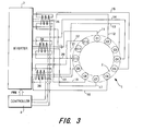
- FIG. 3 is similar to FIG. 2, but shows a schematic view of a current detection device detecting a current of another rotating electric machine of a plurality of rotating electric machines which use a common stator, according to the first embodiment of this invention.
- FIG. 4 is a schematic view of a current detection device detecting a current of one rotating electric machine of a plurality of rotating electric machines which use a common stator, according to a second embodiment of this invention.
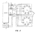
- FIG. 5 is similar to FIG. 4, but shows a schematic view of a current detection device detecting a current of another rotating electric machine of a plurality of rotating electric machines which use a common stator, according to the second embodiment of this invention.
- FIG. 1 an example of a plurality of rotating electric machines using a common stator according to a first embodiment of this invention will be described.
- This example has two rotating electric machines.
- the two rotating electric machines use a common stator 2 and constitute an integrated composite motor 1.
- Rotors 3, 4 are disposed on the inside and outside of the cylindrical stator 2.
- the outer rotor 3 and the inner rotor 4 are disposed in a coaxial orientation with respect to the stator 2.
- the stator 2 and the outer rotor 3 make up one rotating electric machine.
- the inner rotor 4 and the stator 2 make up the other rotating electric machine.
- the inner rotor 4 has two pairs of magnetic poles.
- the S pole and the N pole are disposed alternately at an interval of 90°.
- the outer rotor 3 has twice the number of pairs of magnetic poles as the inner rotor 4. In other words, the outer rotor 3 has four N poles and four S poles which are disposed alternately at an interval of 45°.
- a three-phase alternating current (Iu, Iv, Iw) generating a rotating magnetic field for rotating the outer rotor 3 flows in the twelve coils C1 - C12.
- Iu Ic 1 cos(2 ⁇ F 1 t+ ⁇ )
- Iv Ic 1 cos(2 ⁇ F 1 t-2 ⁇ /3+ ⁇ )
- Iw Ic 1 cos(2 ⁇ F 1 t-4 ⁇ /3+ ⁇ )
- a six-phase alternating current (Ia, Ib, Ic, Id, Ie, If) generating a rotating magnetic field for rotating the inner rotor 4 flows in the twelve coils C1 - C12.
- Ia Ic 2 cos(2 ⁇ F 2 t+ ⁇ )
- Ib Ic 2 cos(2 ⁇ F 2 t- ⁇ /3+ ⁇ )
- Ic Ic 2 cos(2 ⁇ F 2 t-2 ⁇ /3+ ⁇ )
- Id Ic 2 cos(2 ⁇ F 2 t- ⁇ + ⁇ )
- Inner-rotor currents the currents which flow in the coils C1 - C12 in order to control the inner rotor
- I 2 1 - I 2 12 these currents are given as shown below using Equation (2).
- I 2 11
- I1 - I12 When the composite currents which flow in the coils C1 - C12 of the stator 2 are designated as I1 - I12, these currents may obviously be expressed as shown below using the current components Iu - Iw from Equation (1) and the current components Ia - If from Equation (2).
- I1 Iu+Ia
- I2 Iv+Ib
- I3 Iw+Ic
- I4 Iu+Id
- composite currents I1 - I12 are set in this manner, two magnetic fields comprising the rotating magnetic field for rotating the outer rotor 3 and the rotating magnetic field for rotating the inner rotor 4 are simultaneously generated in a single coils unit C1-C12, that is to say, in a single stator. Consequently, the first rotating electric machine comprising the outer rotor 3 and the stator 2 and the second rotating electric machine comprising the inner rotor 4 and the stator 2 are independently controlled.
- the rotating magnetic field for rotating the outer rotor 3 does not apply a rotational force to the inner rotor 4 and the rotating magnetic field for rotating the inner rotor 4 does not apply a rotational force to the outer rotor 3.
- the principle for this is disclosed in US Pat. No 6, 049, 152.
- the setting of the current components Iu, Iv, Iw is performed in synchrony with the rotational phase of the outer rotor 3 and the setting of the current components Ia, Ib, Ic, Id, Ie, If is performed in synchrony with the rotational phase of the inner rotor 4.
- An advance or delay of the current phase is set with respect to the direction of torque. This is the same as the settings performed in a synchronous motor.
- the controller 8 shown in FIG. 2 is a microcomputer having a central processing unit (CPU), a read only memory (ROM), a random access memory (RAM) and an input/output interface (I/O interface).
- the controller 8 determines the command values for the d-axis and the q-axis currents for each rotating electric machine and performs a known vector control for each rotating electric machine.
- the actual values for the d-axis and the q-axis currents are calculated on the basis of the output signal from a rotational angle sensor for the outer rotor and the output signal from a rotational angle sensor for the inner rotor.
- the controller 8 generates a voltage command value for generating a three-phase current for the first rotating electric machine and a voltage command value for generating a six-phase current for the second rotating electric machine so that the actual d-axis current and the actual q-axis current coincide with the command values.
- a composite voltage command value is generated by combining the voltage command values for each rotating electric machine.
- a PWM signal is generated on the basis of the carrier signal and the composite voltage command value. The PWM signal is transmitted to the inverter 7 as shown in FIG. 2 and FIG. 3.
- the composite motor 1 may be combined with the engine. This may be briefly described as directly connecting the outer rotor to the engine output shaft and directly connecting the inner rotor 4 to the drive shaft.
- the first rotating electric machine is mainly operated as a motor and the second rotating electric machine is mainly operated as a generator.
- the controller 8 is provided with the function of determining a target torque for the engine in addition to a target torque for the first rotating electric machine as well as a target torque and a target rotation speed for the second rotating electric machine.
- the current sensors are preferably through-type current sensors which detect a current based on the magnetic field generated by the current.
- the current sensor has a function of detecting the sum of the currents provided to the current sensor and is not limited to the through-type current sensor.
- a through-type current sensor is generally provided with a magnetic core through which the supply line passes. The magnetic field generated in the magnetic core by the current passing in the supply line is detected by a magnetic sensor such as a Hall sensor.
- the supply lines 11, 14, 17, 20 to the coils 1, 4, 7, 10 are together led through a single current sensor 31.
- This current sensor 31 detects a current component Iu for the outer-rotor current.
- Equation (9) When Equation (3) and Equation (4) are substituted in the above equation, Equation (9) below is derived.
- the initial phase angles ⁇ , ⁇ are normally set to zero.
- the current sensor 31 detects only the current component Iu of the outer-rotor current multiplied by the number of pairs of magnetic poles. In this case, the multiple of pole pairs is four.
- the supply lines 12, 15, 18, 21 to the coils C2, C5, C8, C11 are collected and pass through the same current sensor 32 as shown in FIG. 2.
- the supply lines 13, 16, 19, 22 to the coils C3, C6, C9, C12 are collected and pass through the same current sensor 33.
- the remaining current components Iv, Iw for the outer-rotor current are detected as shown below as a multiple of four.
- all current components Iu, Iv, Iw can be determined by the three current sensors 31, 32, 33.
- the current sensor simultaneously detects the currents flowing in a set of two supply lines, such as (11,14), (17,20), (12,15), (18,21), (13,16), (19,22).
- current components for example Iu, of the frequency F 1 flow in phase
- current components for example Ia and Id, of the frequency F 2 flow with different phases from one another.
- the current. components of the frequency F 2 deviate at a regular phase interval of 180°.
- the second current components flow with opposite phases to one another in the set of two supply lines.
- the supply lines 11, 17 to the coils C1, C7 are collected with the supply lines 14, 20 to the coils C4, C10 which pass in the opposite direction through the current sensor 34, and applied to a single current sensor 34. If a direction in the supply line from the inverter 7 to the composite motor 1 is taken to be a plus direction, when the supply lines 11, 17 to the coils C1, C7 pass through the current sensor 34 in a plus direction from the inlet of the current sensor 34, the supply lines 14, 20 to the coils C4, C10 pass through the current sensor 34 in a minus direction from the inlet of the current sensor 34.
- the inlet of the current sensor 34 is on the left side of FIG. 3.
- Equation (13) When Equation (3) and Equation (4) are substituted in the above equation, Equation (13) below is derived.
- the initial phase angles ⁇ , ⁇ are normally set to zero.
- the supply lines 12, 15, 18, 21 to the coils C2, C5, C8, C11 pass together through the current sensor 35.
- the supply lines 12, 18 to the coils C2, C8 pass in the opposite direction through the current sensor 35 with respect to the supply lines 15, 21 to the coils C5, C11.
- the supply lines 13, 16, 19, 22 to the coils C3, C6, C9, C12 pass together through the current sensor 36, the supply lines 13, 19 to the coils C3, C9 pass in the opposite direction through the current sensor 35 with respect to the supply lines 16, 22 to the coils C6, C12.
- the supply lines 14, 17, 20, 21 to the coils C4, C7, C10, C1 pass together through a current sensor (not shown)
- the supply lines 14, 20 to the coils C4, C10 pass in the opposite direction through the current sensor with respect to the supply lines 17, 11 to the coils C7, C1.
- the supply lines 15, 18, 21, 12 to the coils C5, C8, C11, C2 pass together through a current sensor (not shown)
- the supply lines 15, 21 to the coils C5, C11 pass in the opposite direction through the current sensor with respect to the supply lines 18, 12 to the coils C8, C2.
- the supply lines 16, 19, 22, 13 to the coils C6, C9, C12, C3 pass together through a current sensor (not shown), the supply lines 6, 22 to the coils C6, C12 pass in the opposite direction through the current sensor to the supply lines 19, 13 to the coils C9, C3.
- the current components Ib, Ic, Id, Ie, If are detected as a multiple of four as shown below.
- the supply lines are collected and passed through the current sensors 31, 32, 33 so that the phases of the current components of the outer-rotor current of a frequency of F 1 are the same and the components of the inner-rotor current of a frequency of F 2 cancel out to a value of zero.
- the supply lines are collected and passed through the current sensors 34, 35, 36 so that the phases of the current components of the inner-rotor current of a frequency of F 2 are the same and the components of the outer-rotor current of a frequency of F 1 cancel out to a value of zero.
- the plurality of rotating electric machines are a first rotating electric machine 42 and a second rotating electric machine 43. These two rotating electric machines do not use a common stator.
- the number of pole pairs in the rotor of the first rotating electric machine 42 and the rotor of the second rotating electric machine 43 are both three.
- the rotor of the first rotating electric machine 42 is termed the "first rotor”
- the rotor of the second rotating electric machine 43 is termed the "second rotor”.
- the stators 44, 45 of each rotating electric machine have three coils per magnetic pole making a total of nine (3 ⁇ 3) coils.
- the stator 44 of the first rotating electric machine 42 is hereafter termed the “first stator” and the stator 45 of the second rotating electric machine 43 is hereafter termed the “second stator”.
- the rotating magnetic field with respect to the first rotor is generated by a three-phase current (Ip, Iq, Ir) deviating at a phase of 120° (2 ⁇ /3) in the three coils as shown below.
- Ip Ic 3 cos(2 ⁇ F 3 t+ ⁇ )
- Iq Ic 3 cos(2 ⁇ F 3 t-2 ⁇ /3+ ⁇ )
- Ir Ic 3 cos(2 ⁇ F 3 t-4 ⁇ /3+ ⁇ )
- Ik Ic 4 cos(2 ⁇ F 4 t+ ⁇ )
- Il Ic 4 cos(2 ⁇ F 4 t-2 ⁇ /3+ ⁇ )
- Im Ic 4 cos(2 ⁇ F 4 t-4 ⁇ /3+ ⁇ )
- first rotor current controlling the first rotor which flow in each of the nine coils D1 - D9 of the first stator 44
- I 3 1 - I 3 9 the currents controlling the first rotor which flow in each of the nine coils D1 - D9 of the first stator 44
- I 3 1 Ic 3 cos(2 ⁇ F 3 t+ ⁇ )
- I 3 2 Ic 3 cos(2 ⁇ F 3 t-2 ⁇ /3+ ⁇ )
- I 3 3 Ic 3 cos(2 ⁇ F 3 t-4 ⁇ /3+ ⁇ )
- I 3 4 Ic 3 cos(2 ⁇ F 3 t+ ⁇ )
- I 3 5 Ic 3 cos(2 ⁇ F 3 t-2 ⁇ /3+ ⁇ )
- I 3 6 Ic 3 cos(2 ⁇ F 3 t-4 ⁇ /3+ ⁇ )
- I 3 7 Ic 3 cos(2 ⁇ F 3 t+ ⁇ )
- I 3 8 Ic 3 cos(2 ⁇ F 3 t-2 ⁇ /3+ ⁇ )
- I 3 9 Ic 3 cos(2 ⁇ F 3 t-4 ⁇ /3+ ⁇ )
- I 4 1 Ic 4 cos(2 ⁇ F 4 t+ ⁇ )
- I 4 2 Ic 4 cos(2 ⁇ F 4 t+ ⁇ )
- I 4 3 Ic 4 cos(2 ⁇ F 4 t+ ⁇ )
- I 4 4 Ic 4 cos(2 ⁇ F 4 t-2 ⁇ /3+ ⁇ )
- I 4 5 Ic 4 cos(2 ⁇ F 4 t-2 ⁇ /3+ ⁇ )
- I 4 6 Ic 4 cos(2 ⁇ F 4 t-2 ⁇ /3+ ⁇ )
- I 4 7 Ic 4 cos(2 ⁇ F 4 t-4 ⁇ /3+ ⁇ )
- I 4 8 Ic 4 cos(2 ⁇ F 4 t-4 ⁇ /3+ ⁇ )
- I 4 9 Ic 4 cos(2 ⁇ F 4 t-4 ⁇ /3+ ⁇ )
- the composite currents I1 - I9 respectively are provided in the supply lines 111-119.
- the three-phase current (Ip, Iq, Ir) does not flow in the stator 45 of the second rotating electric machine 43 and the three-phase current (Ik, Il, Im) does not flow in the stator 44 of the first rotating electric machine 43 because each set of coils (D1, D2, D3) (D4, D5, D6) (D7, D8, D9) (E1, E4, E7) (E2, E5, E8) (E3, E6, E9) forms a three-phase coils unit in which three coils are connected by a star connection.
- Six current sensors 51 - 56 are disposed in the following manner with respect to the total of nine supply lines 111 - 119.
- the supply lines 111, 114, 117 to the coils D1, D4, D7 of the first stator 44 and the coils E1, E4, E7 of the second stator 45 are collected and pass through the current sensor 51.
- Equation (21) and Equation (22) are substituted into this equation, the following equation is derived.
- the initial phase angle ⁇ and ⁇ are set to a value of zero.
- the second-rotor currents I 4 I, I 4 4, I 4 7 do not appear in the detected value of the sensor 51.
- the detected value of the sensor 51 is the current component Ip of the first-rotor current which is multiplied by the number of pole pairs. In this embodiment, the multiple of pole pairs is three.
- the supply lines 112, 115, 118 to the coils D2, D5, D8 in the first stator 44 and to the coils E2, E5, E8 in the second stator 45 are collected and pass through the same current sensor 52.
- the supply lines 113, 116, 119 to the coils D3, D6, D9 in the first stator 44 and to the coils E3, E6, E9 of the second stator 45 are collected and pass through the same current sensor 53.
- the supply lines 111, 112, 113 to the coils D1, D2, D3, in the first stator 44 and to the coils E1, E2, E3, in the second stator 45 are collected and pass through the same current sensor 54.
- Detected value of sensor 54 (I 3 1+I 3 2+I 3 3)+(I 4 1+I 4 2+I 4 3)
- Equation (21) and Equation (22) are substituted into this equation, the following equation is derived.
- the initial phase angle ⁇ and ⁇ are set to a value of zero.
- the first-rotor currents I 3 I, I 3 4, I 3 7 do not appear in the detected value of the sensor 54. This allows the 0°- phase current component Ik of the second-rotor current to be detected.
- the supply lines 114, 115, 116 to the coils D4, D5, D6 in the first stator 44 and to the coils E4, E5, E6 in the second stator 45 are collected and pass through the same current sensor 55.
- the supply lines 117 118, 119 to the coils D7, D8, D9 in the first stator 44 and to the coils E7, E8, E9 of the second stator 45 are collected and pass through the same current sensor 56.
- all the current components Ik, Il, Im of the second-rotor current are determined by three current sensors 54 - 56.
- the current sensor simultaneously detects the currents flowing in a set of three supply lines, such as (111,112,113), (111,114,117).
- current components, for example Ip, of the frequency F 3 flow in phase
- current components, Ik, Il, Im, of the frequency F 4 flow with different phases from one another.
- the three current components of the frequency F 4 deviate at regular phase intervals of 120°.
- the current components of the frequency F 4 cancel out to zero in the set of supply lines.
- the supply lines 111, 114, 117 to the coils D1, D4, D7 in the first stator 44 and to the coils E1, E4, E7 in the second stator 45 are collected and pass through the same current sensor 51.
- the fact that a current component with a frequency F 4 is detected by the current sensor 51 indicates that one of the coils E1, E4, E7 of the second stator 45 has become disconnected.
- ⁇ I in Equation (34) above is a function of the frequency F4.
- the actual d-current and the actual q-current take an oscillating waveform when a disconnection in one of the coils E1, E4, E7 in the second stator 45 has occurred.
- the actual d-current and the actual q-current display substantially fixed characteristics.
- the actual d-current and the actual q-current take an oscillating waveform.
- the supply lines are collected and passed through the same current sensor so that the phase of the current components of the first frequency (F 1 , F 3 ) is the same and the current components of the second frequency (in the first embodiment F 2 , in the second embodiment F 4 ) cancel out to a value of zero.
- the supply lines are collected and passed through the same current sensor so that the phase of the current components of the second frequency (F 2 , F 4 ) is the same and the current components of the first frequency (F 1 , F 3 ) cancel out to a value of zero.
- the number of supply lines has been described taking a maximum number (four lines in the first embodiment and three lines in the second embodiment) as an example.
- the invention is not limited in this regard.
- the supply lines 11, 14 to the coils C1, C4 or the supply lines 17, 20 to the coils C7, C10 are collected into a single set of two supply lines and pass through the same current sensor 31.
- the detected values of the current sensor 31 at this time are as shown below.
- the supply lines 12 and 15 to the coils C2 and C5 or the supply lines 18 and 21 to the coils C8 and C11 are collected and pass through the same current sensor 32.
- the supply lines 13 and 16 to the coils C3 and C6 or the supply lines 19 and 22 to the coils C9 and C12 are collected and pass through the same current sensor 33.
Landscapes
- Engineering & Computer Science (AREA)
- Power Engineering (AREA)
- Transportation (AREA)
- Mechanical Engineering (AREA)
- Control Of Ac Motors In General (AREA)
- Measurement Of Current Or Voltage (AREA)
- Control Of Motors That Do Not Use Commutators (AREA)
Applications Claiming Priority (2)
| Application Number | Priority Date | Filing Date | Title |
|---|---|---|---|
| JP2001207633 | 2001-07-09 | ||
| JP2001207633A JP3551164B2 (ja) | 2001-07-09 | 2001-07-09 | 回転電機の電流検出装置 |
Publications (2)
| Publication Number | Publication Date |
|---|---|
| EP1276223A1 true EP1276223A1 (de) | 2003-01-15 |
| EP1276223B1 EP1276223B1 (de) | 2007-11-21 |
Family
ID=19043587
Family Applications (1)
| Application Number | Title | Priority Date | Filing Date |
|---|---|---|---|
| EP02015082A Expired - Lifetime EP1276223B1 (de) | 2001-07-09 | 2002-07-05 | Gerät zur Stromerfassung |
Country Status (4)
| Country | Link |
|---|---|
| US (1) | US6844699B2 (de) |
| EP (1) | EP1276223B1 (de) |
| JP (1) | JP3551164B2 (de) |
| DE (1) | DE60223628T2 (de) |
Cited By (1)
| Publication number | Priority date | Publication date | Assignee | Title |
|---|---|---|---|---|
| CN108604875A (zh) * | 2016-02-17 | 2018-09-28 | 三菱电机株式会社 | 电力变换装置 |
Families Citing this family (3)
| Publication number | Priority date | Publication date | Assignee | Title |
|---|---|---|---|---|
| JP3671884B2 (ja) * | 2001-08-30 | 2005-07-13 | 日産自動車株式会社 | 回転電機 |
| US7715698B2 (en) * | 2005-08-31 | 2010-05-11 | Thor Power Corporation | Control electronics for brushless motors |
| WO2009144957A1 (ja) * | 2008-05-30 | 2009-12-03 | パナソニック株式会社 | 同期電動機駆動システム |
Citations (3)
| Publication number | Priority date | Publication date | Assignee | Title |
|---|---|---|---|---|
| JP2000048996A (ja) * | 1998-07-29 | 2000-02-18 | Fukui Prefecture | 6相多重立体放電装置 |
| EP1087518A2 (de) * | 1999-09-27 | 2001-03-28 | Nissan Motor Co., Ltd. | Regelungsvorrichtung und -Verfahren für einen Motorgenerator |
| US6232741B1 (en) * | 1998-10-12 | 2001-05-15 | Denso Corporation | Reluctance type motor apparatus and driving method capable of reducing ripples in motor output torque |
Family Cites Families (6)
| Publication number | Priority date | Publication date | Assignee | Title |
|---|---|---|---|---|
| DE69912504T2 (de) * | 1998-03-25 | 2004-05-06 | Nissan Motor Co., Ltd., Yokohama | Motor/Generator |
| JP3480300B2 (ja) * | 1998-03-25 | 2003-12-15 | 日産自動車株式会社 | 回転電機 |
| JP3496519B2 (ja) * | 1998-06-10 | 2004-02-16 | 日産自動車株式会社 | 回転電機の制御装置 |
| JP3663997B2 (ja) * | 1999-09-27 | 2005-06-22 | 日産自動車株式会社 | 複数ロータモータ |
| US6639337B1 (en) * | 1999-09-27 | 2003-10-28 | Nissan Motor Co., Ltd. | Motor/generator with multiple rotors |
| JP3719136B2 (ja) * | 2000-01-17 | 2005-11-24 | 日産自動車株式会社 | 回転電機および駆動システム |
-
2001
- 2001-07-09 JP JP2001207633A patent/JP3551164B2/ja not_active Expired - Fee Related
-
2002
- 2002-07-05 EP EP02015082A patent/EP1276223B1/de not_active Expired - Lifetime
- 2002-07-05 DE DE60223628T patent/DE60223628T2/de not_active Expired - Fee Related
- 2002-07-09 US US10/190,578 patent/US6844699B2/en not_active Expired - Fee Related
Patent Citations (3)
| Publication number | Priority date | Publication date | Assignee | Title |
|---|---|---|---|---|
| JP2000048996A (ja) * | 1998-07-29 | 2000-02-18 | Fukui Prefecture | 6相多重立体放電装置 |
| US6232741B1 (en) * | 1998-10-12 | 2001-05-15 | Denso Corporation | Reluctance type motor apparatus and driving method capable of reducing ripples in motor output torque |
| EP1087518A2 (de) * | 1999-09-27 | 2001-03-28 | Nissan Motor Co., Ltd. | Regelungsvorrichtung und -Verfahren für einen Motorgenerator |
Cited By (2)
| Publication number | Priority date | Publication date | Assignee | Title |
|---|---|---|---|---|
| CN108604875A (zh) * | 2016-02-17 | 2018-09-28 | 三菱电机株式会社 | 电力变换装置 |
| CN108604875B (zh) * | 2016-02-17 | 2022-02-01 | 三菱电机株式会社 | 电力变换装置 |
Also Published As
| Publication number | Publication date |
|---|---|
| DE60223628T2 (de) | 2008-10-30 |
| JP2003033073A (ja) | 2003-01-31 |
| US20030011255A1 (en) | 2003-01-16 |
| DE60223628D1 (de) | 2008-01-03 |
| US6844699B2 (en) | 2005-01-18 |
| JP3551164B2 (ja) | 2004-08-04 |
| EP1276223B1 (de) | 2007-11-21 |
Similar Documents
| Publication | Publication Date | Title |
|---|---|---|
| US8169116B2 (en) | Electric motor | |
| JP5672278B2 (ja) | 3相回転機の制御装置 | |
| JP3711955B2 (ja) | 回転電機の制御装置 | |
| US20110204833A1 (en) | Controller for motor | |
| CN103036497B (zh) | 同步电机的控制装置和控制方法 | |
| US9088193B2 (en) | Motor exciting device and motor exciting method and motor control device and motor control method | |
| JP2002223600A (ja) | モータ制御装置 | |
| US6624601B2 (en) | Control device for plurality of rotating electrical machines | |
| JP3958274B2 (ja) | 放電制御装置、放電制御方法及びそのプログラム | |
| JP2009183051A (ja) | 同期機の制御装置 | |
| JPH11332298A (ja) | 電動機制御装置および制御方法 | |
| EP1276223A1 (de) | Gerät zur Stromerfassung | |
| JP2006149146A (ja) | 無結線式モータの駆動制御装置及び無結線式モータの駆動制御装置を使用した電動パワーステアリング装置 | |
| JP5496231B2 (ja) | 同期機の制御装置 | |
| JP2019068642A (ja) | 多相回転機の制御装置 | |
| JP4115785B2 (ja) | インバータ制御装置 | |
| JP2001045789A (ja) | モータ制御装置 | |
| JP2018191475A (ja) | アクチュエータ制御装置 | |
| JP4448300B2 (ja) | 同期機の制御装置 | |
| WO2018235586A1 (ja) | 極数切替回転電機の制御装置 | |
| JPH1070865A (ja) | 無軸受回転機械装置 | |
| JP2002238296A (ja) | 複合電流駆動回転電機 | |
| JP5011509B2 (ja) | 回転電機の制御装置 | |
| JPH09168271A (ja) | 同期モータ及びその制御方法 | |
| JPH05344694A (ja) | リラクタンス形回転機 |
Legal Events
| Date | Code | Title | Description |
|---|---|---|---|
| PUAI | Public reference made under article 153(3) epc to a published international application that has entered the european phase |
Free format text: ORIGINAL CODE: 0009012 |
|
| 17P | Request for examination filed |
Effective date: 20020705 |
|
| AK | Designated contracting states |
Kind code of ref document: A1 Designated state(s): AT BE BG CH CY CZ DE DK EE ES FI FR GB GR IE IT LI LU MC NL PT SE SK TR |
|
| AX | Request for extension of the european patent |
Free format text: AL;LT;LV;MK;RO;SI |
|
| 17Q | First examination report despatched |
Effective date: 20030311 |
|
| AKX | Designation fees paid |
Designated state(s): DE FR GB |
|
| RIC1 | Information provided on ipc code assigned before grant |
Ipc: H02K 19/10 20060101ALI20070322BHEP Ipc: H02P 9/12 20060101AFI20070322BHEP Ipc: H05H 1/32 20060101ALI20070322BHEP Ipc: H02K 16/00 20060101ALI20070322BHEP |
|
| GRAP | Despatch of communication of intention to grant a patent |
Free format text: ORIGINAL CODE: EPIDOSNIGR1 |
|
| GRAS | Grant fee paid |
Free format text: ORIGINAL CODE: EPIDOSNIGR3 |
|
| GRAA | (expected) grant |
Free format text: ORIGINAL CODE: 0009210 |
|
| RIN1 | Information on inventor provided before grant (corrected) |
Inventor name: ARIMITSU, MINORU Inventor name: MAEDA, SHOUICHI |
|
| AK | Designated contracting states |
Kind code of ref document: B1 Designated state(s): DE FR GB |
|
| REG | Reference to a national code |
Ref country code: GB Ref legal event code: FG4D |
|
| REF | Corresponds to: |
Ref document number: 60223628 Country of ref document: DE Date of ref document: 20080103 Kind code of ref document: P |
|
| ET | Fr: translation filed | ||
| PLBE | No opposition filed within time limit |
Free format text: ORIGINAL CODE: 0009261 |
|
| STAA | Information on the status of an ep patent application or granted ep patent |
Free format text: STATUS: NO OPPOSITION FILED WITHIN TIME LIMIT |
|
| 26N | No opposition filed |
Effective date: 20080822 |
|
| PGFP | Annual fee paid to national office [announced via postgrant information from national office to epo] |
Ref country code: FR Payment date: 20090710 Year of fee payment: 8 |
|
| PGFP | Annual fee paid to national office [announced via postgrant information from national office to epo] |
Ref country code: DE Payment date: 20090702 Year of fee payment: 8 Ref country code: GB Payment date: 20090701 Year of fee payment: 8 |
|
| GBPC | Gb: european patent ceased through non-payment of renewal fee |
Effective date: 20100705 |
|
| REG | Reference to a national code |
Ref country code: FR Ref legal event code: ST Effective date: 20110331 |
|
| PG25 | Lapsed in a contracting state [announced via postgrant information from national office to epo] |
Ref country code: DE Free format text: LAPSE BECAUSE OF NON-PAYMENT OF DUE FEES Effective date: 20110201 |
|
| REG | Reference to a national code |
Ref country code: DE Ref legal event code: R119 Ref document number: 60223628 Country of ref document: DE Effective date: 20110201 |
|
| PG25 | Lapsed in a contracting state [announced via postgrant information from national office to epo] |
Ref country code: FR Free format text: LAPSE BECAUSE OF NON-PAYMENT OF DUE FEES Effective date: 20100802 |
|
| PG25 | Lapsed in a contracting state [announced via postgrant information from national office to epo] |
Ref country code: GB Free format text: LAPSE BECAUSE OF NON-PAYMENT OF DUE FEES Effective date: 20100705 |