EP1276123B1 - Drehschaltermechanismus für eine bedienungstafel - Google Patents
Drehschaltermechanismus für eine bedienungstafel Download PDFInfo
- Publication number
- EP1276123B1 EP1276123B1 EP00970025A EP00970025A EP1276123B1 EP 1276123 B1 EP1276123 B1 EP 1276123B1 EP 00970025 A EP00970025 A EP 00970025A EP 00970025 A EP00970025 A EP 00970025A EP 1276123 B1 EP1276123 B1 EP 1276123B1
- Authority
- EP
- European Patent Office
- Prior art keywords
- drive pieces
- drive
- movable piece
- pieces
- rotary knob
- Prior art date
- Legal status (The legal status is an assumption and is not a legal conclusion. Google has not performed a legal analysis and makes no representation as to the accuracy of the status listed.)
- Expired - Lifetime
Links
Images


Classifications
-
- H—ELECTRICITY
- H01—ELECTRIC ELEMENTS
- H01H—ELECTRIC SWITCHES; RELAYS; SELECTORS; EMERGENCY PROTECTIVE DEVICES
- H01H19/00—Switches operated by an operating part which is rotatable about a longitudinal axis thereof and which is acted upon directly by a solid body external to the switch, e.g. by a hand
- H01H19/005—Electromechanical pulse generators
-
- H—ELECTRICITY
- H01—ELECTRIC ELEMENTS
- H01H—ELECTRIC SWITCHES; RELAYS; SELECTORS; EMERGENCY PROTECTIVE DEVICES
- H01H19/00—Switches operated by an operating part which is rotatable about a longitudinal axis thereof and which is acted upon directly by a solid body external to the switch, e.g. by a hand
- H01H19/02—Details
- H01H19/025—Light-emitting indicators
-
- H—ELECTRICITY
- H01—ELECTRIC ELEMENTS
- H01H—ELECTRIC SWITCHES; RELAYS; SELECTORS; EMERGENCY PROTECTIVE DEVICES
- H01H19/00—Switches operated by an operating part which is rotatable about a longitudinal axis thereof and which is acted upon directly by a solid body external to the switch, e.g. by a hand
- H01H19/54—Switches operated by an operating part which is rotatable about a longitudinal axis thereof and which is acted upon directly by a solid body external to the switch, e.g. by a hand the operating part having at least five or an unspecified number of operative positions
- H01H19/60—Angularly-movable actuating part carrying no contacts
- H01H19/62—Contacts actuated by radial cams
-
- H—ELECTRICITY
- H01—ELECTRIC ELEMENTS
- H01H—ELECTRIC SWITCHES; RELAYS; SELECTORS; EMERGENCY PROTECTIVE DEVICES
- H01H19/00—Switches operated by an operating part which is rotatable about a longitudinal axis thereof and which is acted upon directly by a solid body external to the switch, e.g. by a hand
- H01H19/54—Switches operated by an operating part which is rotatable about a longitudinal axis thereof and which is acted upon directly by a solid body external to the switch, e.g. by a hand the operating part having at least five or an unspecified number of operative positions
- H01H19/60—Angularly-movable actuating part carrying no contacts
- H01H19/63—Contacts actuated by axial cams
-
- H—ELECTRICITY
- H01—ELECTRIC ELEMENTS
- H01H—ELECTRIC SWITCHES; RELAYS; SELECTORS; EMERGENCY PROTECTIVE DEVICES
- H01H19/00—Switches operated by an operating part which is rotatable about a longitudinal axis thereof and which is acted upon directly by a solid body external to the switch, e.g. by a hand
- H01H19/005—Electromechanical pulse generators
- H01H2019/006—Electromechanical pulse generators being rotation direction sensitive, e.g. the generated pulse or code depends on the direction of rotation of the operating part
-
- H—ELECTRICITY
- H01—ELECTRIC ELEMENTS
- H01H—ELECTRIC SWITCHES; RELAYS; SELECTORS; EMERGENCY PROTECTIVE DEVICES
- H01H2219/00—Legends
- H01H2219/054—Optical elements
- H01H2219/062—Light conductor
-
- H—ELECTRICITY
- H01—ELECTRIC ELEMENTS
- H01H—ELECTRIC SWITCHES; RELAYS; SELECTORS; EMERGENCY PROTECTIVE DEVICES
- H01H2219/00—Legends
- H01H2219/054—Optical elements
- H01H2219/062—Light conductor
- H01H2219/0622—Light conductor only an illuminated ring around keys
-
- H—ELECTRICITY
- H01—ELECTRIC ELEMENTS
- H01H—ELECTRIC SWITCHES; RELAYS; SELECTORS; EMERGENCY PROTECTIVE DEVICES
- H01H25/00—Switches with compound movement of handle or other operating part
- H01H25/06—Operating part movable both angularly and rectilinearly, the rectilinear movement being along the axis of angular movement
- H01H25/065—Operating part movable both angularly and rectilinearly, the rectilinear movement being along the axis of angular movement using separate operating parts, e.g. a push button surrounded by a rotating knob
-
- H—ELECTRICITY
- H01—ELECTRIC ELEMENTS
- H01H—ELECTRIC SWITCHES; RELAYS; SELECTORS; EMERGENCY PROTECTIVE DEVICES
- H01H3/00—Mechanisms for operating contacts
- H01H3/32—Driving mechanisms, i.e. for transmitting driving force to the contacts
- H01H3/42—Driving mechanisms, i.e. for transmitting driving force to the contacts using cam or eccentric
Definitions
- the present invention relates to a rotary switch mechanism for an operation panel that may be utilized in, for instance, an air-conditioning system for vehicles.
- a rotary switch in the related art disclosed in Japanese Unexamined Patent Publication No. H 9-288934 comprises a switch board having a plurality of switch contact points, an elastic pressure application plate that includes a plurality of arm units and holds contact portions provided at the individual arm units on the switch contact points and a rotating body that is rotatably provided on the switch board and includes depressing portions provided at the lower surface of the switch board to come in contact with the arm units and thus push down the arm units.
- Document EP 0 771 681 discloses a device according to the preamble of claim 1.
- an object of the present invention is to provide a rotary switch mechanism for an operation panel that allows ample space on a printed board, facilitates the design process for designing electronic parts and the like on the printed board and achieves good attachability for the switch knob.
- the present invention which simply requires the drive pieces to be provided over specific intervals at the circumferential edge at the end of the rotary knob located further inward at the operation panel and the detection switch for detecting a passage of and the direction of the passage of the drive pieces to be provided within or in the vicinity of the range of the movement of the drive pieces, e.g., on the printed board, ample space is assured on the printed board, thereby solving the problem discussed earlier.
- the drive pieces formed at the rotary knob may project out along the radius of the rotary knob or they may project out along the axial direction from the external circumferential edge at the end of the rotary knob.
- the detection switch be constituted of a physical detection switch having a movable piece that is capable of moving along a direction corresponding to the direction of the passage of the drive pieces, and such a movable piece may be set either parallel to the drive pieces or perpendicular to the drive pieces.
- the present invention is further characterized in that an intermediate transmission mechanism that converts the intervals between the individual drive pieces to a distance required for the movement of the movable piece is provided between the drive pieces and the movable piece. For instance, if the rotary knob has a smaller diameter and thus the intervals between the drive pieces, too, are smaller, the movement of the movable piece at the detection switch over such a small distance between the drive pieces cannot be detected. In such a case, by providing the intermediate transmission mechanism, it becomes possible to allow the movable piece of the detection switch to move over a large enough distance to allow a detection thereof.
- the intermediate transmission mechanism should comprise a first arm that is caused to move by the drive pieces, a second arm that causes the movable piece to move and a supporting point portion provided between the first arm and the second arm, with the length of the first arm and the length of the second arm set in correspondence to the ratio of the interval between the drive pieces and the distance required for the movement of the movable piece.
- the first arm and the second arm may be set on a single straight line, may be set perpendicular to each other or may be set at a specific angle to each other.
- the drive pieces may each be constituted of a tooth of a drive gear formed at the end of the rotary knob and the intermediate transmission mechanism may be constituted of a working gear which interlocks with the drive gear and rotates as the drive pieces move and a working portion that is secured to the working gear and rotates as the working gear rotates to cause the movable piece to move, with the ratio of the number of teeth of the drive gear and the number of teeth of the drive gear and the number of the working portions set in correspondence to the ratio of the pitch at the drive gear and the distance required for the movement of the movable piece.
- the rotary switch mechanism includes a plurality of detection switches positioned at phases different from the phases of the drive pieces and the individual detection switches may sequentially detect the passage of and the direction of the passage of the drive pieces while the drive pieces move over a distance equivalent to the interval between the individual drive pieces.
- the individual detection switches can sequentially detect the passage of and the direction of the passage of the drive pieces while the drive pieces move over the distance equivalent to the interval between the drive pieces, i.e., while they pass over a single pitch of the drive pieces and a desired number of signals representing the rotational angle of the rotary knob corresponding to the number of drive pieces can be generated even when the intervals between the individual drive pieces is set large enough to allow the required movement of the movable piece.
- the detection switch is constituted of a physical detection switch that detects the passage of and the direction of the passage of the drive pieces by detecting the movement of the working piece in the example described above
- the detection switch according to the present invention may be constituted of an optical detection switch having a light emitting element and a light receiving element, which detects the passage of and the direction of the passage of the drive pieces by detecting a change of light while the drive pieces pass between the light emitting element and the light receiving element instead.
- the detection switch may take on any structure as long as it is capable of detecting the passage of and the direction of the passage of the drive pieces through detection of a change occurring in an electromagnetic wave, an acoustic wave, an electrical field, a magnetic field or the like instead of a change of a visible light beam as described above.
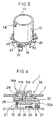
- FIGS. 1 and 2 illustrate an example of an operation panel for an air-conditioning system.
- a rotary switch mechanism 3 projecting out at the front surface of a case 2 and a push switch mechanism 4 located on the inside of a dial unit 11 of the rotary switch mechanism 3, for instance, are provided, with an indicator unit 13 provided at the center of the push switch mechanism 4.
- a light emitting indicator unit 14 is provided at the front surface of the case 2.
- the push switch mechanism 4 which may be, for instance, an auto switch for turning on/off the air-conditioning system, comprises a push knob 5 slidably mounted at a cylindrical mounting portion 7 provided continuously to the case 2 and a push switch 6 provided on a printed board 8 that is in contact with the circumferential edge of the push knob 5 at the inner end, and a specific space 10 is formed within the push switch mechanism 4.
- the rotary switch mechanism 3 comprises a rotary knob 16 constituted of the dial unit 11 projecting out at the surface of the case 2 and a cylindrical drive unit 12 interlocking with the dial unit 11, and a detection switch 15.
- an interlocking piece 18 that interlocks with the dial unit 11 is formed at a circumferential edge 17, as shown in FIG. 3, at one end of the cylindrical drive unit 12, with drive pieces 20 which project out along the radius of the cylindrical drive unit 12 formed over a specific interval along the circumference at a circumferential edge 19 at the other end of the cylindrical drive unit 12.
- the detection switch 15 which is a so-called bidirectional three-contact point switch of the known art, may comprise a movable piece 21 the front and of which moves around a shaft 21a along the direction in which the drive pieces 20 move as the drive pieces 20 pass while maintaining contact, a cam portion 22 that communicates the movement of the movable piece 21, a switch spring 24 that causes contact points 24a and 24b formed at the front end thereof as the cam portion 22 moves, contact points T1, T2 and T3 formed at the surface against which the contact points 24a and 24b slide, a case 23 at which the contact points T1, T2 and T3 are provided with the cam portion 22 and the switch spring 24 housed therein and the shaft 21a rotatably fixed thereto and a lid portion 23a that includes an opening through which the drive pieces 20 project out and hold arms 22a and 22b of the cam portion 22.
- the movable piece 21 is pushed down along direction P1 as the drive pieces 21 travel along direction P1 and, as a result, the arm 22a of the cam portion 22 causes the switch spring 24 to move along direction A.
- the terminal 24a comes in contact with the contact point T2 and the terminal 24b comes in contact with the contact point T1, thereby setting the terminals T1 and T2 in a state of contact.
- the switch spring 24 since the movable piece 21 becomes reset to its original position after one of the drive pieces 20 passes over, the switch spring 24, too, returns to its original position, thereby cutting off the terminals T1 and T2 from each other again. In this manner, when the drive pieces 20 move along direction P1 by one unit of pitch a single signal is generated at the T2 terminal.
- the switch spring 24 moves along direction B and then returns to its original position to set the terminals T1 and T3 in a state of contact, thereby generating a single signal at the T3 terminal.
- the contact point T1 and the contact point T3 that achieve contact when the temperature setting is raised enter a state of contact six times at the detection switch 15, thereby generating six signals indicating direction P2 at the terminal T3 to allow the driver to verify that the temperature setting has been changed from 25°C to 28°C.
- the contact point T1 and the contact point T2 that achieve contact when lowering the temperature setting enter a contact state eight times thereby generating eight signals indicating direction P1 at the terminal T2 and making it possible to verify that the temperature setting has been changed from 28°C to 24°C.
- reference numeral 26b indicates a light path through which light is provided to the indicator unit 14 and reference numeral 27 indicates a light bulb constituting a light source provided on the printed board 8. While a light bulb is utilized as the light source in this embodiment, a light emitting diode may instead be employed.
- a rotary knob 16A in a rotary switch mechanism 3A comprises a dial unit 11A projecting out from the case 2, a rod unit 29 mounted at a cylindrical fitting portion 28 provided at the center of the dial unit 11A and a disk unit 30 provided at an end of the rod unit 29.
- Drive pieces 20A extending along the radius of the disk unit 30 are formed over specific intervals around the disk unit 30 to cause a movement of a movable piece 28 of the detection switch 15.
- an electronic part 32 which may be a resistor, a capacitor or an IC, which guides the light from the light bulb 27 to achieve a light emission at the circumferential edge of the dial unit 11A.
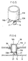
- drive pieces 20B are formed so as to project out along the axis of the cylindrical drive unit 12B over a specific interval along the circumference from a circumferential edge 19b at the other end of the cylindrical drive unit 12B. Since the drive pieces 20B do not project out along the radial direction in this embodiment, there is a likelihood of the measurement along the axial direction being greater than in the previous embodiments. However, a space is assured at the circumferential edge of the cylindrical drive unit 12B along the radial direction.
- a rotary switch mechanism 3B shown in FIG. 6 includes a rotary knob 16B achieved by forming a dial unit 11B and the cylindrical drive unit 12B in the third embodiment and as an integrated unit with a light source 35 provided on the printed board 8 at the center of the rotary knob 16B.
- the 16B in the embodiment is constituted of a transparent resin, a colored transparent resin or a colored opaque resin such as a milk-white resin, and a light emission is achieved at the rotary knob 16B itself by utilizing the light source 35.
- a ring constituted of a transparent resin, a colored transparent resin or a colored opaque resin such as a milk-white resin taking on a color different from the color of the rotary knob 16B is provided at the external circumference of the rotary knob 16B.
- cylindrical drive unit 12B and the rotary knob 16B are formed as an integrated unit in the third embodiment, they may be formed as separate parts and then may be integrated with each other through fitting or the like, instead.
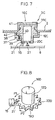
- a flange portion 42 distends outward along the radial direction from a specific position at the cylindrical drive unit 12B, a groove portion 40 running along the flange portion 42 is formed at the lower side surface of the flange portion 42, a part of the groove portion 40 has a greater depth for positioning purposes and the position is set as a ball 38 of a click mechanism 37 goes into the deeper part. This position corresponds to a position of the drive pieces 20C.
- the click mechanism in the embodiment is constituted of the ball 38 pressed into the groove portion 40 by a spring
- the click mechanism may instead be constituted of a plate spring, for instance.
- the dial unit 11C in the embodiment is constituted as a part separate from the cylindrical drive unit 12C by using a transparent resin or the like and a film 41 for blocking light is formed over the area where it is not necessary to emit light to ensure that light is emitted only where needed.
- drive pieces 20D at a circumferential edge 19D at the other end of a cylindrical drive unit 12D constituting a rotary knob 16E are formed as gear teeth and the detection switch 15 is provided along the radial direction. Since the detection switch 15 is provided along the radial direction in this case, adequate space is assured along the axial direction.
- drive pieces 20E at a circumferential edge 19E at the other end of a cylindrical drive unit 12E constituting a rotary knob 16E are formed as gear teeth and the detection switch 15 is provided on a sub-printed board 8A set perpendicular to the main printed board 8 shown in the figures referred to earlier. Since this allows the detection switch 15 to be mounted at any position as long as it is provided in the vicinity of the cylindrical drive unit 12E, a higher degree of freedom is afforded in design.
- drive pieces 20F formed as gear teeth at a circumferential edge 19F at the other end of a cylindrical drive unit 12F are set within the range of the bottom surface of the cylindrical drive unit 12F.
- plate like drive pieces 20F at a circumferential edge 19G at the other end of a cylindrical drive unit 12G are formed within the range of the bottom surface of the 12F.
- the measurement along the radial direction can be reduced compared to those in the fifth and sixth embodiments shown in FIGS. 8 and 9 respectively, as in the seventh embodiment shown in FIG. 10.
- an intermediate transmission mechanism 50 is provided between the drive pieces 20 and the movable piece 21 in a structure in which the pitch of the drive pieces 20 formed at the cylindrical drive unit 12 constituting the rotary knob 16 is not large enough to allow the required movement of the movable piece 21 at the detection switch 15, i.e., in a structure in which the rotary knob 16 has a small radius.
- the intermediate transmission mechanism 50 comprises a first arm 52 and a second arm 53 provided on the two opposite sides of a rotational support point 51 and a spring 55 constituting a holding mechanism 54 that holds the first and second arms 52 and 53 at specific positions.
- the front end of the first arm 52 is caused to move by the drive pieces 20, whereas a working portion 56 that moves the movable piece 21 is provided at the front end of the second arm 53.
- the working portion 56 includes an interlocking groove 57 that interlocks with the movable piece 21 and its side surface toward the detection switch 15 is formed in an arc extending over a specific length so as to ensure that the movable piece 21 is not allowed to disengage from the working portion 56.
- the ratio of the length L1 of the first arm 52 and the length L2 of the second arm 53 should be set equal to or slightly larger than the ratio of the pitch P1 of the drive pieces 20 and the operating pitch P2 of the movable piece 21 (L1/L2 ⁇ P1 / P2).
- the cylindrical drive unit 12 needs to have a minimum diameter of 46mm to generate a single ON signal in correspondence to a rotational angle of 10° by which the cylindrical drive unit 12 is rotated since the movable piece 21 at the detection switch 15 requires an operating distance of 4mm.
- the diameter of the cylindrical drive unit 12 is smaller than 46mm, e.g., 23mm, the pitch of the drive pieces 20 is 2mm and, accordingly, by setting the ratio of the lengths of the first and second arms 52 and 53 at the intermediate transmission mechanism 50 equal to or larger than 1:2, the operating pitch P2 of the detection switch 15 can be set equal to or larger than 4mm, and thus, an ON signal can be generated at the detection switch 15 in correspondence to the rotational range of 10° over which the cylindrical drive unit 12 is rotated.
- first arm 52 and the second arm 53 in the intermediate transmission mechanism 50 achieved in the ninth embodiment shown in FIG. 12 are provided on a single straight line and the detection switch 15 is provided on an extension of the straight line
- the first arm 52 and the second arm 53 in the tenth embodiment shown in FIG. 13 are set perpendicular to each other extending from the rotational support point 51, with the detection switch 15 provided at a position different from that assumed in the ninth embodiment.
- the detection switch 15 is provided along the perpendicular direction in the embodiment, the position of the detection switch 15 can be varied freely by setting the second arm 53 at a specific angle relative to the position of the first arm 52.
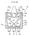
- the drive pieces 20 are constituted of the teeth of a drive gear 60 formed at the cylindrical drive unit 12, and an intermediate transmission mechanism 50B is constituted of a working gear 61 that interlocks with the drive gear 60 and at least one working portion 62 that rotates together with the working gear 61.
- the ratio of the radius of the drive gear 60 and the radius of the working gear 61 and the gear ratio need to be set to 9:1 as there are four working portions 62.
- the ratio of the radii and the gear ratio can be reduced by increasing the number of working portions 62, the ratio of the radius of the drive gear 60 and the radius of the working gear 61 and the gear ratio should be adjusted by taking into consideration the pitch of the working portions 62 to achieve further versatility.
- the pitch of the drive pieces 20 becomes smaller than the operating pitch of the movable piece 21, and accordingly, the angle (phase) ⁇ 1 of the drive pieces 20 formed around the cylindrical drive unit 12 is set larger than the minimum angle requirement (phase) and detection switches 15 are each provided at a phase ⁇ 2 which is different from the phase ⁇ 1 in the twelfth embodiment so as to allow the individual detection switches 15 to sequentially output signals when the drive pieces 20 move over a specific range.
- the angle (phase) ⁇ 1 formed by adjacent drive pieces 20 is 20° as shown in FIG. 5 and two detection switches are provided in conjunction with this structure
- the position of the second detection switch 15B is set at a position at a 30° phase, a 50° phase, a 70° phase ... or a 330° phase relative to the position of the first detection switch 15A.
- the drive pieces 20 move by 10°, the drive pieces 20 cause either the movable piece 21A or the movable piece 21B of the first detection switch 15A or the second detection switch 15B to move, and when the drive pieces 20 move by another 10°, the other movable piece 21A or 21B is caused to move.
- the first detection switch 15A and the second detection switch 15B each output a signal as the cylindrical drive unit 12 is rotated by 20° and, consequently, two signals are obtained in correspondence to a 20° rotation of the cylindrical drive unit 12.
- a second detection switch should be provided at a 30n + 10 phase and a third detection switch should be provided at a 30n + 20 phase relative to the position of a first detection switch, to obtain a signal in correspondence to every 10° rotation of the cylindrical drive unit 12 even though the drive pieces 20 are formed over 30° intervals.
- the drive pieces 20 By forming the drive pieces 20 over a distance from each other that allows the minimum operating pitch (approximately 4mm) for the movable pieces 21 and providing the plurality of detection switches 15 at specific phases (central angles) different from the phases (central angles) of the drive pieces 20, as described above, an ON signal can be obtained through one of the detection switches in correspondence to a specific angle by which the rotary knob 16 is rotated.
- ⁇ 1 representing the phase of the drive pieces 20
- M representing the number of detection switches provided
- the phase ⁇ 2 at which an Fth detection switch should be set can be determined through the following formula (1).
- n is a natural number and 0 ⁇ ⁇ 2 ⁇ 360.
- ⁇ ⁇ 2 n ⁇ ⁇ ⁇ 1 + F ⁇ ⁇ 1 / M
- the detection switch 15 is constituted of a physical detection switch that detects the passage of the drive pieces in the structures described above, the detection switch in they may each be constituted of an optical detection switch having a light emitting element and a light receiving element, which detects the passage of and the direction of the passage of the drive pieces by detecting a change of light manifesting while the drive pieces pass between the light emitting element and the light receiving element, instead.
- the detection switch 15 may each be constituted of an optical detection switch having a light emitting element and a light receiving element, which detects the passage of and the direction of the passage of the drive pieces by detecting a change of light manifesting while the drive pieces pass between the light emitting element and the light receiving element, instead.
- a light emitting source for the indicator unit is provided at the center of the rotary knob, only the light receiving element may be provided to detect the passage of and the direction of the passage of the drive pieces.
- a detection switch utilized in the present invention may take on any structure as long as it is capable of detecting the passage of and the direction of the passage of the drive pieces through detection of a change occurring in an electromagnetic wave, an acoustic wave or the like instead of a change of a visible light beam described above.
- the detection switch needs only to be provided within the range of movement of the drive pieces or in the vicinity of the range of their movement, e.g., on a printed board, and thus, ample space is assured on the printed board to improve the degree of freedom with regard to the layout of the parts on the printed board. Since this allows the path of light emitted from the light source on the printed board to be designed with freedom, the degree of design freedom is further improved.
- the drive pieces at the rotary knob and the movable piece of the detection switch are not fixed to each other, it is not necessary to align the rotary knob with the detection switch with absolute precision, and thus, the rotary switch mechanism can be mounted with ease.
- the detection switch can be constituted of an inexpensive switch, the production cost can be reduced.
Landscapes
- Rotary Switch, Piano Key Switch, And Lever Switch (AREA)
- Switches With Compound Operations (AREA)
- Switch Cases, Indication, And Locking (AREA)
- Mechanisms For Operating Contacts (AREA)
Claims (8)
- Drehschaltermechanismus (3) für eine Bedienungstafel (2) mit mehreren Moduseinstellungen, der das Wählen einer der mehreren Moduseinstellungen gestattet, indem eine der den mehreren Moduseinstellungen entsprechenden Positionen gewählt wird, mit
einem zylindrischen Drehknopf (16), der einen Abschnitt (16A, 16B) aufweist, der an der Vorderfläche der Bedienungstafel vorsteht, und der in jeder der den mehreren Moduseinstellungen entsprechenden Positionen anhalten kann,
Antriebsteilen (20), die in bestimmten Phasen an einem Umfangsrand am Ende des Drehknopfs weiter innen an der Bedienungstafel ausgebildet sind und sich entlang dem Umfang des Drehknopfs bewegen, wenn sich der Drehknopf dreht, und gekennzeichnet durch
mehrere Erfassungsschalter (15), die an Phasen vorgesehen sind, die sich von den Phasen, an denen die Antriebsteile vorgesehen sind, unterscheiden, dadurch gekennzeichnet, dass
die einzelnen Erfassungsschalter so angeordnet sind, dass sie nacheinander das Vorbeigehen der Antriebsteile und die Richtung ihres Vorbeigehens erfassen, während sich die Antriebsteile über eine Strecke bewegen, die dem Abstand zwischen den Antriebsteilen entspricht. - Drehschaltermechanismus nach Anspruch 1, dadurch gekennzeichnet, dass die am Drehknopf ausgebildeten Antriebsteile entlang dem Radius des Drehknopfs vorstehen.
- Drehschaltermechanismus nach Anspruch 1, dadurch gekennzeichnet, dass die am Drehknopf ausgebildeten Antriebsteile entlang der axialen Richtung von einem äußeren Umfangsrand am Ende des Drehknopfs vorstehen.
- Drehschaltermechanismus nach Anspruch 2 oder 3, dadurch gekennzeichnet, dass die Erfassungsschalter jeweils ein bewegliches Teil aufweisen, das sich entlang einer der Richtung des Vorbeigehens entsprechenden Richtung bewegen kann, wenn jedes Antriebsteil vorbeigeht, und sich entlang einer Richtung nach außen erstreckt, die mit der Richtung zusammenpasst, in der sich die Antriebsteile erstrecken.
- Drehschaltermechanismus nach Anspruch 2 oder 3, dadurch gekennzeichnet, dass die Erfassungsschalter jeweils ein bewegliches Teil aufweisen, das sich entlang einer der Richtung des Vorbeigehens entsprechenden Richtung bewegen kann, wenn jedes Antriebsteil vorbeigeht, und sich entlang einer Richtung nach außen erstreckt, die senkrecht zu der Richtung verläuft, in der sich die Antriebsteile erstrecken.
- Drehschaltermechanismus nach Anspruch 4 oder 5, dadurch gekennzeichnet, dass zwischen den Antriebsteilen und dem beweglichen Teil ein Zwischenkommunikationsübertragungsmechanismus vorgesehen ist, der den Abstand zwischen den Antriebsteilen zu einem Abstand umwandelt, der für die Bewegung des beweglichen Teils notwendig ist.
- Drehschaltermechanismus nach Anspruch 6, dadurch gekennzeichnet, dass der Zwischenübertragungsmechanismus Folgendes aufweist:einen ersten Arm, der durch die Antriebsteile zur Bewegung veranlasst wird,einen zweiten Arm, der das bewegliche Teil zur Bewegung veranlasst, undeinen zwischen dem ersten Arm und dem zweiten Arm vorgesehenen Stützpunktabschnitt, wobei die Länge des ersten Arms und die Länge des zweiten Arms entsprechend dem Verhältnis des Abstands zwischen den Antriebsteilen und dem für die Bewegung des beweglichen Teils benötigten Abstand eingestellt werden.
- Drehschaltermechanismus nach Anspruch 6, dadurch gekennzeichnet, dass
die Antriebsteile jeweils aus einem Zahn eines am Ende des Drehknopfs ausgebildeten Antriebszahnrads bestehen,
der Zwischenübertragungsmechanismus aus einem Arbeitszahnrad, das in das Antriebszahnrad eingreift und sich dreht, während sich die Antriebsteile bewegen, und aus einem Arbeitsabschnitt besteht, der am Arbeitszahnrad befestigt ist und sich dreht, während sich das Arbeitszahnrad dreht, damit sich das bewegliche Teil bewegt, und
das Verhältnis der Anzahl von Zähnen des Antriebszahnrads und der Anzahl von Zähnen des Arbeitszahnrads und der Anzahl der Arbeitsabschnitte entsprechend dem Verhältnis der Steigung bzw. Teilung am Antriebszahnrad zu dem für die Bewegung des beweglichen Teils benötigten Abstand eingestellt wird.
Applications Claiming Priority (3)
| Application Number | Priority Date | Filing Date | Title |
|---|---|---|---|
| JP2000047544 | 2000-02-24 | ||
| JP2000047544A JP4066037B2 (ja) | 2000-02-24 | 2000-02-24 | 操作パネルの回転スイッチ機構 |
| PCT/JP2000/007418 WO2001063632A1 (fr) | 2000-02-24 | 2000-10-24 | Systeme d'interrupteur rotatif pour panneau de commande |
Publications (3)
| Publication Number | Publication Date |
|---|---|
| EP1276123A1 EP1276123A1 (de) | 2003-01-15 |
| EP1276123A4 EP1276123A4 (de) | 2005-06-22 |
| EP1276123B1 true EP1276123B1 (de) | 2007-11-28 |
Family
ID=18569781
Family Applications (1)
| Application Number | Title | Priority Date | Filing Date |
|---|---|---|---|
| EP00970025A Expired - Lifetime EP1276123B1 (de) | 2000-02-24 | 2000-10-24 | Drehschaltermechanismus für eine bedienungstafel |
Country Status (5)
| Country | Link |
|---|---|
| US (1) | US6670567B1 (de) |
| EP (1) | EP1276123B1 (de) |
| JP (1) | JP4066037B2 (de) |
| DE (1) | DE60037279T2 (de) |
| WO (1) | WO2001063632A1 (de) |
Families Citing this family (28)
| Publication number | Priority date | Publication date | Assignee | Title |
|---|---|---|---|---|
| EP1389788B1 (de) * | 2002-08-13 | 2009-01-07 | Vestel Elektronik Sanayi ve Ticaret A.S. | Funktionsanzeige zum Anzeigen des Zustandes einer Vorrichtung |
| DE10313621A1 (de) * | 2003-03-26 | 2004-10-28 | Siemens Ag | Bedienelement mit mehreren Handhaben |
| JP2005032450A (ja) | 2003-07-07 | 2005-02-03 | Matsushita Electric Ind Co Ltd | スイッチ装置 |
| DE10342334B4 (de) * | 2003-09-11 | 2013-01-31 | Preh Gmbh | Bedienelement |
| JP4031775B2 (ja) | 2004-04-28 | 2008-01-09 | 三菱重工業株式会社 | 車両用空調装置のダイヤル式スイッチ機構 |
| DE102005032508B4 (de) * | 2004-07-15 | 2021-05-20 | BSH Hausgeräte GmbH | Bedienelement mit Leuchtquelle |
| FR2878369A1 (fr) * | 2004-11-24 | 2006-05-26 | Valeo Climatisation Sa | Bouton de commande a encodeur mecanique |
| JP4636545B2 (ja) * | 2005-08-02 | 2011-02-23 | 株式会社東海理化電機製作所 | 車両用の空調スイッチ装置 |
| TW200729261A (en) * | 2006-01-19 | 2007-08-01 | Benq Corp | Switch with light emitting function |
| DE102008004501A1 (de) * | 2008-01-16 | 2009-07-30 | Diehl Ako Stiftung & Co. Kg | Betätigungseinrichtung |
| US20100116629A1 (en) * | 2008-11-12 | 2010-05-13 | Milo Borissov | Dual action push-type button |
| DE102009005008A1 (de) * | 2009-01-17 | 2010-07-22 | Diehl Ako Stiftung & Co. Kg | Berührungsempfindlicher Tastschalter |
| JP5278140B2 (ja) * | 2009-04-24 | 2013-09-04 | 株式会社オートネットワーク技術研究所 | 回転式操作装置 |
| JP5458687B2 (ja) * | 2009-06-16 | 2014-04-02 | 株式会社オートネットワーク技術研究所 | 車載用スイッチ |
| JP5310571B2 (ja) * | 2010-01-13 | 2013-10-09 | 住友電装株式会社 | 回転操作装置 |
| DE102010036237B4 (de) * | 2010-09-03 | 2015-10-22 | Diehl Ako Stiftung & Co. Kg | Kapazitiver Berührungs- und/oder Annäherungsschalter |
| TWI423291B (zh) * | 2010-09-03 | 2014-01-11 | Primax Electronics Ltd | 旋鈕機構 |
| CN102412082A (zh) * | 2010-09-21 | 2012-04-11 | 致伸科技股份有限公司 | 旋钮机构 |
| CN102623228B (zh) * | 2011-01-28 | 2014-08-27 | 致伸科技股份有限公司 | 旋钮机构 |
| US8872048B2 (en) * | 2011-11-22 | 2014-10-28 | Nidec Motor Corporation | Illuminated thumbwheel switch assembly |
| FR2991790A1 (fr) * | 2012-06-07 | 2013-12-13 | Peugeot Citroen Automobiles Sa | Encodeur pour molette de selection rotative |
| JP6295903B2 (ja) * | 2014-01-22 | 2018-03-20 | 株式会社デンソー | 回転操作装置 |
| US10018514B2 (en) * | 2014-02-17 | 2018-07-10 | Haier Us Appliance Solutions, Inc. | Cooktop temperature sensors and methods of operation |
| DE102014211305A1 (de) * | 2014-06-13 | 2015-12-17 | BSH Hausgeräte GmbH | Haushaltsgerät mit einem Drehschalter und Verfahren zu seinem Betrieb |
| DE102014226618A1 (de) * | 2014-12-19 | 2016-06-23 | Siemens Aktiengesellschaft | Drehbetätiger |
| DE102015215769A1 (de) * | 2015-08-19 | 2017-02-23 | BSH Hausgeräte GmbH | Bedienvorrichtung für ein Haushaltsgerät mit einem Lichtleiter zur Mehrzonenbeleuchtung einer Frontkappe mit unterschiedlichen Lichtintensitäten, Haushaltsgerät mit einer derartigen Bedienvorrichtung und Verfahren zum Betreiben einer Bedienvorrichtung |
| JP6611529B2 (ja) * | 2015-09-11 | 2019-11-27 | キヤノン株式会社 | 電子機器 |
| US9916948B2 (en) * | 2015-12-31 | 2018-03-13 | Continental Automotive Systems, Inc. | Button with flexible light conductor |
Family Cites Families (14)
| Publication number | Priority date | Publication date | Assignee | Title |
|---|---|---|---|---|
| JPS5951423A (ja) | 1982-09-17 | 1984-03-24 | キヤノン株式会社 | 電子機器 |
| DE3326308A1 (de) * | 1983-07-21 | 1985-01-31 | Standard Elektrik Lorenz Ag, 7000 Stuttgart | Impulsgenerator |
| DE3326307A1 (de) * | 1983-07-21 | 1985-01-31 | Standard Elektrik Lorenz Ag, 7000 Stuttgart | Impulsgeber |
| JPS60129033U (ja) * | 1984-02-06 | 1985-08-29 | 株式会社小松製作所 | 多回転体用リミツトスイツチ |
| JPH028218U (de) * | 1988-06-29 | 1990-01-19 | ||
| JP3505300B2 (ja) * | 1995-10-31 | 2004-03-08 | アルプス電気株式会社 | 車載用回転検出装置 |
| DE19652619A1 (de) * | 1996-12-18 | 1998-06-25 | Fahrzeugklimaregelung Gmbh | Inkrementaler Weggeber |
| MY120975A (en) * | 1997-02-13 | 2005-12-30 | Sony Corp | Switch device. |
| DE19705576C2 (de) * | 1997-02-14 | 1999-01-07 | Reinhausen Maschf Scheubeck | Stellungsmeldeanordnung |
| FR2762711B1 (fr) * | 1997-04-28 | 2001-12-07 | Eaton Corp | Organe de commande a molette rotative |
| JP3843583B2 (ja) * | 1998-03-12 | 2006-11-08 | 松下電器産業株式会社 | レバースイッチとその操作方法 |
| JP2000164072A (ja) | 1998-11-26 | 2000-06-16 | Olympus Optical Co Ltd | スイッチ装置 |
| DE19964133A1 (de) * | 1999-11-22 | 2001-06-13 | Preh Elektro Feinmechanik | Drehschalter |
| JP2001312942A (ja) * | 2000-04-27 | 2001-11-09 | Sony Corp | 通信端末装置及びスイッチ装置 |
-
2000
- 2000-02-24 JP JP2000047544A patent/JP4066037B2/ja not_active Expired - Lifetime
- 2000-10-24 EP EP00970025A patent/EP1276123B1/de not_active Expired - Lifetime
- 2000-10-24 DE DE60037279T patent/DE60037279T2/de not_active Expired - Lifetime
- 2000-10-24 US US10/204,541 patent/US6670567B1/en not_active Expired - Fee Related
- 2000-10-24 WO PCT/JP2000/007418 patent/WO2001063632A1/ja active IP Right Grant
Also Published As
| Publication number | Publication date |
|---|---|
| US6670567B1 (en) | 2003-12-30 |
| EP1276123A1 (de) | 2003-01-15 |
| DE60037279D1 (de) | 2008-01-10 |
| JP4066037B2 (ja) | 2008-03-26 |
| DE60037279T2 (de) | 2008-10-02 |
| JP2001236861A (ja) | 2001-08-31 |
| EP1276123A4 (de) | 2005-06-22 |
| WO2001063632A1 (fr) | 2001-08-30 |
Similar Documents
| Publication | Publication Date | Title |
|---|---|---|
| EP1276123B1 (de) | Drehschaltermechanismus für eine bedienungstafel | |
| EP0844418B1 (de) | Positionsdetektionsschalter mit kombinierter, elektronischer Steuereinheit für automatische Getriebe | |
| US6130425A (en) | Rotating detecting device of multi-rotation body | |
| US20050022617A1 (en) | Rotation detecting device and automobile with the same | |
| EP0497316B1 (de) | Anzeigevorrichtung für Fahrzeuge | |
| KR100828905B1 (ko) | 차량용 계측기 | |
| KR19990082435A (ko) | 래치된 스위치 장치 | |
| WO1995004918A1 (fr) | Dispositif indicateur | |
| JP3970756B2 (ja) | 照光式スイッチ装置 | |
| GB2319312A (en) | Shift lever position detecting apparatus | |
| EP0789227B1 (de) | Vorrichtung zur Ermittlung der Position eines sich bewegenden Körpers | |
| JP2008076111A (ja) | 指針計器 | |
| US6606961B1 (en) | Pointer instrument | |
| US5907139A (en) | Position detector switch with planetary gearing | |
| JP2009294076A (ja) | 表示装置 | |
| JP2011044251A (ja) | 回転操作装置 | |
| JP3722098B2 (ja) | 発光指針計器 | |
| JP4706584B2 (ja) | スイッチ操作装置 | |
| JP4178671B2 (ja) | 指示計器 | |
| JP2019087311A (ja) | 表示装置及び回転スイッチ | |
| WO2021177347A1 (ja) | 車載用操作装置 | |
| JP2005024318A (ja) | 操作装置 | |
| JP4537284B2 (ja) | ダイヤルスイッチ | |
| EP1091192A1 (de) | Beleuchtbares Zeigerinstrument mit Mitteln zur Verminderung der Lichthofbildung | |
| JP2017111858A (ja) | 回転操作装置 |
Legal Events
| Date | Code | Title | Description |
|---|---|---|---|
| PUAI | Public reference made under article 153(3) epc to a published international application that has entered the european phase |
Free format text: ORIGINAL CODE: 0009012 |
|
| 17P | Request for examination filed |
Effective date: 20020816 |
|
| AK | Designated contracting states |
Kind code of ref document: A1 Designated state(s): AT BE CH CY DE DK ES FI FR GB GR IE IT LI LU MC NL PT SE |
|
| RBV | Designated contracting states (corrected) |
Designated state(s): DE FR |
|
| A4 | Supplementary search report drawn up and despatched |
Effective date: 20050511 |
|
| RIC1 | Information provided on ipc code assigned before grant |
Ipc: 7H 01H 19/62 A Ipc: 7H 01H 19/00 B |
|
| GRAP | Despatch of communication of intention to grant a patent |
Free format text: ORIGINAL CODE: EPIDOSNIGR1 |
|
| GRAS | Grant fee paid |
Free format text: ORIGINAL CODE: EPIDOSNIGR3 |
|
| GRAA | (expected) grant |
Free format text: ORIGINAL CODE: 0009210 |
|
| AK | Designated contracting states |
Kind code of ref document: B1 Designated state(s): DE FR |
|
| REF | Corresponds to: |
Ref document number: 60037279 Country of ref document: DE Date of ref document: 20080110 Kind code of ref document: P |
|
| ET | Fr: translation filed | ||
| PLBE | No opposition filed within time limit |
Free format text: ORIGINAL CODE: 0009261 |
|
| STAA | Information on the status of an ep patent application or granted ep patent |
Free format text: STATUS: NO OPPOSITION FILED WITHIN TIME LIMIT |
|
| 26N | No opposition filed |
Effective date: 20080829 |
|
| REG | Reference to a national code |
Ref country code: DE Ref legal event code: R082 Ref document number: 60037279 Country of ref document: DE Representative=s name: VON ROHR PATENTANWAELTE PARTNERSCHAFT MBB, DE |
|
| PGFP | Annual fee paid to national office [announced via postgrant information from national office to epo] |
Ref country code: FR Payment date: 20131009 Year of fee payment: 14 Ref country code: DE Payment date: 20131016 Year of fee payment: 14 |
|
| REG | Reference to a national code |
Ref country code: DE Ref legal event code: R119 Ref document number: 60037279 Country of ref document: DE |
|
| PG25 | Lapsed in a contracting state [announced via postgrant information from national office to epo] |
Ref country code: DE Free format text: LAPSE BECAUSE OF NON-PAYMENT OF DUE FEES Effective date: 20150501 |
|
| REG | Reference to a national code |
Ref country code: FR Ref legal event code: ST Effective date: 20150630 |
|
| PG25 | Lapsed in a contracting state [announced via postgrant information from national office to epo] |
Ref country code: FR Free format text: LAPSE BECAUSE OF NON-PAYMENT OF DUE FEES Effective date: 20141031 |