EP1270907A1 - Dispositif a papillon et capteur de papillon dans un moteur a combustion interne - Google Patents
Dispositif a papillon et capteur de papillon dans un moteur a combustion interne Download PDFInfo
- Publication number
- EP1270907A1 EP1270907A1 EP00915347A EP00915347A EP1270907A1 EP 1270907 A1 EP1270907 A1 EP 1270907A1 EP 00915347 A EP00915347 A EP 00915347A EP 00915347 A EP00915347 A EP 00915347A EP 1270907 A1 EP1270907 A1 EP 1270907A1
- Authority
- EP
- European Patent Office
- Prior art keywords
- resistor
- throttle
- throttle valve
- sensor
- valve shaft
- Prior art date
- Legal status (The legal status is an assumption and is not a legal conclusion. Google has not performed a legal analysis and makes no representation as to the accuracy of the status listed.)
- Withdrawn
Links
Images


Classifications
-
- F—MECHANICAL ENGINEERING; LIGHTING; HEATING; WEAPONS; BLASTING
- F02—COMBUSTION ENGINES; HOT-GAS OR COMBUSTION-PRODUCT ENGINE PLANTS
- F02D—CONTROLLING COMBUSTION ENGINES
- F02D9/00—Controlling engines by throttling air or fuel-and-air induction conduits or exhaust conduits
- F02D9/08—Throttle valves specially adapted therefor; Arrangements of such valves in conduits
- F02D9/10—Throttle valves specially adapted therefor; Arrangements of such valves in conduits having pivotally-mounted flaps
- F02D9/1035—Details of the valve housing
- F02D9/105—Details of the valve housing having a throttle position sensor
-
- F—MECHANICAL ENGINEERING; LIGHTING; HEATING; WEAPONS; BLASTING
- F02—COMBUSTION ENGINES; HOT-GAS OR COMBUSTION-PRODUCT ENGINE PLANTS
- F02D—CONTROLLING COMBUSTION ENGINES
- F02D35/00—Controlling engines, dependent on conditions exterior or interior to engines, not otherwise provided for
-
- F—MECHANICAL ENGINEERING; LIGHTING; HEATING; WEAPONS; BLASTING
- F02—COMBUSTION ENGINES; HOT-GAS OR COMBUSTION-PRODUCT ENGINE PLANTS
- F02D—CONTROLLING COMBUSTION ENGINES
- F02D11/00—Arrangements for, or adaptations to, non-automatic engine control initiation means, e.g. operator initiated
- F02D11/06—Arrangements for, or adaptations to, non-automatic engine control initiation means, e.g. operator initiated characterised by non-mechanical control linkages, e.g. fluid control linkages or by control linkages with power drive or assistance
- F02D11/10—Arrangements for, or adaptations to, non-automatic engine control initiation means, e.g. operator initiated characterised by non-mechanical control linkages, e.g. fluid control linkages or by control linkages with power drive or assistance of the electric type
- F02D11/106—Detection of demand or actuation
-
- F—MECHANICAL ENGINEERING; LIGHTING; HEATING; WEAPONS; BLASTING
- F02—COMBUSTION ENGINES; HOT-GAS OR COMBUSTION-PRODUCT ENGINE PLANTS
- F02D—CONTROLLING COMBUSTION ENGINES
- F02D9/00—Controlling engines by throttling air or fuel-and-air induction conduits or exhaust conduits
- F02D9/08—Throttle valves specially adapted therefor; Arrangements of such valves in conduits
- F02D9/10—Throttle valves specially adapted therefor; Arrangements of such valves in conduits having pivotally-mounted flaps
- F02D9/1065—Mechanical control linkage between an actuator and the flap, e.g. including levers, gears, springs, clutches, limit stops of the like
-
- F—MECHANICAL ENGINEERING; LIGHTING; HEATING; WEAPONS; BLASTING
- F16—ENGINEERING ELEMENTS AND UNITS; GENERAL MEASURES FOR PRODUCING AND MAINTAINING EFFECTIVE FUNCTIONING OF MACHINES OR INSTALLATIONS; THERMAL INSULATION IN GENERAL
- F16K—VALVES; TAPS; COCKS; ACTUATING-FLOATS; DEVICES FOR VENTING OR AERATING
- F16K37/00—Special means in or on valves or other cut-off apparatus for indicating or recording operation thereof, or for enabling an alarm to be given
- F16K37/0008—Mechanical means
Definitions
- the present invention relates to a throttle assembly for controlling the flow(amount of the flow) of intake air in an internal combustion engine, as well as a throttle sensor for detecting the degree of opening of a throttle valve used in the throttle device.
- an electronically controlled throttle assembly wherein the operation of a throttle valve in an engine is controlled by an electrically-driven actuator (e.g., a DC motor or a stepping motor).
- an electrically-driven actuator e.g., a DC motor or a stepping motor.
- the electronically controlled throttle assembly controls the throttle valve angle (throttle valve opening) to an optimum value according to the state of an engine and in accordance with a signal indicative of the degree of opening of an accelerator pedal or a traction control signal.
- a sensor for detecting the angle of the throttle valve what is called a throttle sensor (also called an opening meter or a throttle position sensor) is attached to a throttle body.
- the throttle sensor there generally is adopted a potentiometer type sensor, wherein a brush (slider) adapted to rotate together with a throttle valve shaft slides on a resistor, thereby outputting a potential difference signal (sensor detection signal) corresponding to the degree of opening of a throttle valve.
- throttle sensors of this type so far used there are known, for example, such throttle sensors as are disclosed in Japanese Patent Laid Open Nos. 7-343878 and 9-32588, wherein a resistor and a wiring pattern of a potentiometer are formed on a substrate.
- the substrate is attached to a cover of a receptacle portion containing a reduction gear mechanism.
- a brush is attached to a flat surface of a driven gear (or a rotor) mounted on a throttle valve shaft.
- the brush slides on a resistor and a conductor both formed on the substrate (a flat surface). Since the driven gear is used also as a moving element to which the brush of the potentiometer is attached, the number of components used can be so much reduced.
- the present invention basically proposes the following throttle assemblies:
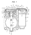
- an electronically controlled throttle assembly is composed principally of a throttle body 1, which may be referred to simply as the body hereinafter, a throttle valve 4, a motor (a throttle valve driving unit or an electrically-driven actuator) 22 for actuating the throttle valve 4, a reduction gear mechanism 100, a sensor (throttle sensor) 101 for detecting the angle ( degree ) of opening, which may be referred to simply as opening hereinafter, of the throttle valve 4, and a cover 16 for protecting a throttle valve shaft 3, motor 22 and reduction gear mechanism 100.
- the body 1 is formed by molding a receptacle portion (intake bore) 2 for the throttle valve 4 and a receptacle portion (motor housing) 1c for the motor 22 integrally with each other.
- the throttle valve 4 is mounted to the shaft 3 with screws 5, and the shaft 3 is supported by bearings 6 and 26 which are installed in the body 1.
- a ball bearing has heretofore been used as a bearing usually adopted.
- a ball bearing and a cap-shaped plain bearing are used as the bearings 6 and 26, respectively. The reason therefor and their details will be described later.
- the ball bearing 6 is secured to a bearing boss 1a through a seal ring 8.
- An inner ring 6a of the ball bearing 6 is press-fitted on an outer periphery of the throttle valve shaft 3, while an outer ring 6b thereof is fitted in an inner periphery of the bearing boss 1a by transition fit (sliding fit).
- the throttle valve shaft 3 projects to the exterior of a side wall of the body 1, and a spring 10, a lever 9, a spring 11, and a final-stage gear (driven gear) 12 in the reduction gear mechanism 100, which will be described later, are fitted on the projecting one end of the throttle valve shaft.
- the plain bearing 26 is mounted by press-fitting for example.
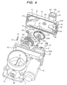
- Throttle valve-related components such as the throttle valve shaft 3, reduction gear mechanism 100 and motor 22 are accommodated within a receptacle portion (case) 1d formed in a side wall of the body 1, the receptacle portion 1d being covered with a synthetic resin cover 16.
- the throttle valve mechanism is disposed so as to be protected by a single cover 16, an opening (a motor mounting opening) 1c' of the motor housing 1c is positioned so as to face the interior of the receptacle portion 1d, through which opening the motor 22 is received into the housing, and an end bracket 22a of the motor is fixed with screws 37 around the opening 1c' (see Figs. 4 to 6).
- Motor terminals 23 formed on the end bracket 22a are positioned near a side wall of the receptacle portion 1d so as to face toward the cover 16 and are connected to relay terminals 24a through relay connectors 33.
- the relay connectors 33 may be in any of various forms. In this embodiment, sleeves are used as the relay connectors 33, slits 34 and 35 (see Fig. 5) are formed respectively in both ends of each of the slits in 90°-shifted directions, and each motor terminal 23 and relay terminal 24a are fitted in the slits 34 and 35.
- the terminals 23 and 24a also face in 90°-shifted directions to match the extending directions of the slits 34 and 35.
- the motor 22 is driven in accordance with an accelerator signal related to the depression quantity of an accelerator pedal and a traction control signal, and the power of the motor 22 is transmitted to the throttle valve shaft 3 through the reduction gear mechanism 100 (a motor pinion 21, an intermediate gear 20, and the final-stage fear 12).
- the pinion 21 is mounted on a motor shaft 27 and the intermediate gear 20 is fitted free on a shaft 19 which is fixed to the throttle body 1.
- the intermediate gear 20 comprises a gear 20a of a larger diameter meshing with the pinion 21 and a gear 20b of a smaller diameter meshing with the gear 12.
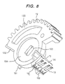
- the final-stage gear 12 is a sectorial gear and, as shown in Figs. 2 to 6 and Fig. 8, a holder 12c for holding brushes (sliders) 13 of a potentiometer is integral with the gear 12.
- the holder 12c is formed so as to be positioned on a peripheral surface of the gear 12 on the side opposite to a toothed area of the same gear.
- the gear 12 has a hole 12h for passing one end 3a' (having at least two flat surfaces) of the throttle valve shaft 3 therethrough.
- the hole 12h is formed in a shape engageable with the one end 3a' of the throttle valve shaft, and through this engagement the gear 12 rotates integrally with the throttle valve shaft 3.
- the lever 9 is fitted free on the outer periphery (circumferential surface) of the throttle valve shaft 3 so that the lever 9 and the gear 12 are pulled toward each other through a spring 11.
- a lug indicated at 12f in Figs. 2 to 4 comes into engagement with a lug 9a of the lever 9 shown in Fig. 6.
- the lug 12f is formed inside the gear 12.
- a lug 12g formed on the gear 12 is for positioning in an assembling work relative to a lug 9b formed on the lever 9 side.
- a spring 10 is a return spring for the throttle valve. One end of the spring 10 is anchored to a spring retaining portion (not shown) provided on the body 1 side and the opposite end thereof is anchored to the lever 9.
- the spring 10 which imparts a return force to the throttle valve shaft through the gear 12, constitutes a known default opening setting mechanism in cooperation with the spring 11 and the lever 9.
- the default opening setting mechanism is for holding an initial opening of the throttle valve larger than a fully closed position during OFF of an engine key (in other words, while the electrically-driven actuator 22 is deenergized). From a default opening position up to a fully open control position, a throttle valve opening is determined in accordance with the balance between the motor power and the spring (return spring) 10. For controlling the throttle valve opening smaller than the default opening, the movement of the lever 9 is prevented by a default opening stopper (not shown) and only the gear 12 and the throttle valve shaft 3 are turned in fully closing direction against the force of the spring 11.
- Numeral 25 denotes a fully closing stopper which defines a mechanical fully closed position of the throttle valve, which fully closed position is determined by abutment of a movable-side stopper 12d against the stopper 25, the stopper 12d being formed on one side of the sectorial gear 12.
- the stopper 12d is fixed with a nut 25a.
- a central portion is constituted by a metallic plate 12a, and a teeth-forming portion 12b, the brush holder 12c and the remaining portion are formed integrally by molding a synthetic resin (a reinforced plastic).
- the metallic plate 12a is insert-molded into the resin portion of the gear.
- the movable-side stopper 12d is integral with the metallic plate 12a.
- the stopper 12d is formed of a metal for improving the accuracy of the stopper position. More particularly, the mechanical fully closed position of the throttle valve serves as a reference point in control and the stopper 12d strikes against the fixed-side fully closing stopper 25 once at every beginning or end of operation. Thus, a high accuracy is required for the stopper 12d, and for this reason the stopper 12d is formed of a metal which is high in rigidity.
- the gear 12 is further provided with a movable-side stopper 12e for defining a fully open position of the throttle valve (Figs. 2 and 8).
- the stopper 12e is formed by molding a synthetic resin integrally with the gear 12 and the brush holder 12c. It suffices for the movable-side fully opening stopper 12e to be formed of a synthetic resin because the stopper 12e generally does not strike against any other component during operation.
- Numeral 12i denotes a guide for engagement of the gear 12 with the lever 9.
- the holder 12c for holding the brushes 13 is formed on a peripheral surface of the gear 12, and two brushes 13 are arranged on an outer surface of the holder 13c side by side in the axial direction of the gear 12.
- a rotational radius from the throttle valve shaft 3 up to the tips of the brushes 13 is set larger than that of the driven gear 12.
- the reason why two brushes 13 are used is that it is intended to use a dual system (two) of throttle sensors.
- the dual system is advantageous in that even in the event of failure of one throttle sensor, the other can be used as a substitute and that even in the event of occurrence of any trouble on one sensor side, the trouble can be detected by processing signals provided from both sensors.
- the brushes 13 are fitted on lugs 12j formed on the holder 12, which lugs 12j are then crushed with heat to fix the brushes onto the holder.
- the brushes 13 may be fixed using screws or an adhesive.
- the gear 12 is fixed to one end 3' of the throttle valve shaft 3 with use of a nut 17 and a washer 18.
- the gear 12 is not limited to the one described above. Such gears as illustrated in Figs. 11 and 12 are also employable.
- the portion of the brush holder 12c is formed of a synthetic resin, while the teeth-forming area 12b and the remaining portion are formed using a sintered metal, and the brush holder 12c is outer-molded to the gear 12 with use of a resin.
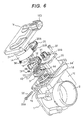
- a great feature of the cover 16 used in this embodiment is that a stator (resistors and wiring patterns) which constitutes the throttle sensor (potentiometer) 101, as well as a wall portion 15 which holds the stator are provided directly in the cover 16.
- resistors and wiring patterns are formed on a substrate as a separate member from the cover and the substrate is then attached to the inner surface of the cover.
- This embodiment intends to make it possible to mold the holding member (wall portion) 15 for the potentiometer (especially resistors and wiring patterns) integrally with the cover 16 while minimizing the influence of such thermal expansion, contraction and deformation of the cover as just referred to above, and to this end the following means is adopted in the embodiment.
- the wall portion 15 is.formed by bending a thin plate in a curvilinearly projecting shape so as to minimize the area thereof occupied on the cover 16 and by raising, like erection, the thus-curved thin plate from the inner surface of the cover.
- the wall portion 15 not only the thermal expansion and contraction of the wall portion can be kept to a minimum, but also the wall portion can be enhanced in its rigidity and is difficult to be thermally deformed.
- a reinforcing rib 15d is formed on the back of the wall portion 15 to enhance the strength of the wall portion.
- the brushes 13 are mounted on the peripheral surface through the holder 12c so that their tips face in the radial direction of the throttle valve shaft 3.
- the brushes 13 may be mounted to a component other than the gear 12.
- a rotor used exclusively for the brush holder may be attached to one end 3a' of the throttle valve shaft 3.
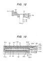
- Resistors R1 and R2 (see Fig. 13) on which the brushes 13 slide are formed on one side of a film 14 by printing together with auxiliary resistors R3, R4, conductors 150, 151, 151' which constitute wiring patterns, conductors 141, 142 for taking out signals, and terminals 161-164. As shown in Figs. 2, 3 and 4, these registers and conductors are arcuately curved together with the film 14. Thus, the resistors R1 and R2 are formed as curved resistors.
- the curved resistors R1 and R2 are omitted their illustration for the convenience of drawing.
- the film 14 may hereinafter be referred to as the curved resistor or film with resistors.
- the wall portion 15 which holds the curved resistor 14 i.e., film with resistors R1 and R2 is formed by molding integrally with the cover 16 which covers one end side of the throttle valve shaft of the throttle body 1.
- the wall portion 15 is formed in conformity with the direction of the bushes 13 and is positioned on the inner surface of the cover 16 and near the corner located on the side opposite to the teeth portion of the gear 12.
- the wall portion 15 is in a curvilinearly erected shape which draws an arc about the axis of the throttle valve shaft 3.
- the conductor 141 for taking out an output signal and the resistor R1, as well as the conductor 142 for taking out an output signal and the resistor R2, are arranged in parallel on one side of the synthetic resin film (sheet) 14, with auxiliary resistors R3 and R4 being further added.
- the conductors 141 and 142 are formed using a material of a low resistivity, e.g., silver paste, while the resistors R3 and R4 are formed using a material of a relatively high resistivity, e.g. carbon, provided no limitation is made thereto.
- a material of a low resistivity e.g., silver paste
- the resistors R3 and R4 are formed using a material of a relatively high resistivity, e.g. carbon, provided no limitation is made thereto.
- the surfaces of the conductors 141, 142, 150, 150', 151 and 151' formed of silver paste for example are also coated with carbon.
- One of the two brushes 13 slides while straddling both resistor R1 and conductor 141, while the other brush 13 slides while straddling both resistor R2 and conductor 142.
- the conductors 141, 142 and the brushes 13 turn conductive with each other in the thickness direction of the carbon film at the brush contact positions (the resistance is low because the film thickness is small), so the carbon film formed on the conductors causes no obstacle. Rather, by coating the conductors (silver paste) with a hard carbon, it is possible to improve the abrasion resistance when the brushes 13 slide on the conductors 141 and 142.
- the resistor R1 is formed between ends 151a and 151b of a wiring conductor, using only a resistive material. Also as to the resistors R2, R3 and R4, they are formed in the same way.
- Fig. 13 the portions corresponding to the resistors R1, R2, R3 and R4 are hatched.
- the resistors and wiring layout in Fig. 13 coincide with the circuit diagram of Fig. 14.
- TPS1 first sensor output terminal
- Vcc positive terminal
- TPS2 second sensor output terminal
- GND ground terminal
- the first sensor output terminal 161 serves as a terminal of the output taking-out conductor 141.
- the conductor 141 is wider at its portion where the associated brush 13 slides.
- the power supply terminal 162 is connected to one end of the auxiliary resistor R3 through the conductor 150, while the opposite end of the auxiliary resistor R3 is connected to one end of the resistor R1 through the conductor end 151a and is also connected to one end of the resistor R2 through the conductor end 151a and the conductor 151.
- the opposite end of the resistor R1 is connected to one end of the auxiliary resistor R4 through the conductors 151b, 151' and 151a'.
- the opposite end of the auxiliary resistor R4 is connected to the ground terminal 164 through conductors 150a' and 150'.
- the second sensor output terminal 163 serves as a terminal of the output taking-out conductor 142.
- the conductor 142 is wider at its portion where the associated brush 13 slides.
- Fig. 14 schematically illustrates a state in which one brush 13 slides while straddling the resistor R1 and the conductor 141 and the other brush 13 slides while straddling the resistor R2 and the conductor 142.
- the brushes 13 move, for example, in an opening direction from a closed state
- the brush 13 which slides on the resistor R1 moves from a low potential side (ground side) to a high potential side (positive side of the power supply), while the brush 13 which slides on the resistor R2 moves from the high to the low potential side.
- An equivalent circuit thereof is illustrated in Fig. 15.
- the sensor output terminals 161 and 162 take out potentials at the brush contact points of the resistors R1 and R2.
- the resistors R1 and R2 are connected at one ends thereof to the positive terminal 162 of the power supply and at the opposite ends to the ground terminal 164. Further, the contact positions of the brushes 13 serve as output points for taking out output voltages, the auxiliary resistor R3 is connected between one ends of the resistors R1, R2 and the positive terminal 162 of the power supply, and the auxiliary resistors R3 and R4 are connected between the opposite ends of the resistors R1, R2 and the ground. terminal 164. In other words, the auxiliary resistors R3 and R4 are provided at both ends of the resistors R1 and R2.
- the resistors R1 and R2 are each several kilo-ohms and the resistors R3 and R4 are each several hundred ohms.
- Fig. 16 illustrates operational characteristics of sensor output voltages relative to movement quantities (throttle valve openings) of the brushes 13.
- the movement quantity 0 corresponds to a fully closed position in control of the throttle valve opening and the movement quantity 40 corresponds to a fully open position in control.
- the numeral 1 ⁇ represents an operational characteristic at the brush contact point potential in resistor R1 and numeral 2 ⁇ represents an operational characteristic at the brush contact point potential in resistor R2.
- a mean value of both operational characteristics 1 ⁇ and 2 ⁇ lies at an intermediate level of potential. If there should occur any trouble in one of the sensor outputs, the mean value of the operational characteristics 1 ⁇ and 2 ⁇ is biased to either the upper or the lower side of the above intermediate level. From this bias it is possible to judge which sensor is out of order.
- auxiliary resistors 33 and 34 it is possible to make gentle the gradient of the sensor output characteristics (operational characteristics 1 ⁇ and 2 ⁇ ) relative to the movement quantity of the brushes (throttle valve opening) and hence possible to diminish output variation characteristics induced by changes in temperature of the resistors for example.
- the potential difference at both ends of the resistors R1 and R2 becomes 4.4V, so that the gradient of output characteristics (operational characteristics 1 ⁇ and 2 ⁇ ) relative to the movement quantity of the brushes becomes smaller than that at the both-end potential difference of 5V of the resistors R1 and R2 (in the absence of the auxiliary resistors R3 and R4). Therefore, even where the operational characteristics vary according to temperatures, the variation range is made narrow to prevent deterioration of the sensor accuracy.
- auxiliary resistors R3 and R4 are disposed at both ends of the resistors R1 and R2, such an auxiliary resistor R3 or R4 as described above may be disposed at only one ends of the resistors R1 and R2, and even in this case it is possible to narrow the variation range of the sensor operation characteristics.
- one end 14a of the film 14 is made small in width and the terminals 161 ⁇ 164 are arranged on one side of the one end 14a.
- a terminal box 32 for insertion therein of one end 14a of the film is formed by the side of the wall portion 15 integrally with the cover 16.
- an upper portion 32a and a side portion 32b close to the wall portion 15 are open so that one end 14a of the film can be inserted therein.
- terminals 161-164 formed at one end of the film 14 and relay terminals 40-1 to 40-4, which communicate with connector terminals, are connected together electrically.
- connector terminals 40 for external connection of the throttle sensors and connector terminals 24 (two in this embodiment) for external connection of the motor power supply are disposed in a connector case 16b of the cover 16.
- Conductors 40' for connection between the connector terminals 40 and the throttle sensors and conductors 24' for connection between the connector terminals 24 and the relay terminals 24a of the motor power supply are insert-molded into the cover 16 (this state is shown in Fig.
- one ends of the conductors 40' i.e., the terminals 40-1 to 40-4
- one ends of the conductors 40' are erected so as to be positioned by the side of one end 15b of the wall portion which is for holding the curved resistors, in other words, they rise so as to project upward from the inner surface of the cover 16, further, one ends 24a of the conductors 24' of the motor power supply are erected from the inner surface of the cover 16.
- One end 14a of the film 14 is inserted into the terminal box 32 in such a manner that the terminals 161 ⁇ 164 formed on the film 14 and the terminals 40-1-40-4 conducted into the terminal box 32 confront each other, and a plate spring 36 serving as a film pressing member is inserted into the terminal box 32, whereby the terminals can be connected positively without separation.
- the relay terminals 24a on the motor side and the motor terminals 23 are connected together through the relay connectors 33.
- the film 14 with curved resistors is affixed to the wall portion 15, the resistors and wiring patterns may be printed directly onto the surface of the wall portion 15.
- a throttle assembly and a throttle sensor capable of contributing to the reduction in the number of components of the throttle sensor, capable of reducing the manufacturing cost and simplifying the assembling work and further capable of ensuring high sensor accuracy and reliability.
Applications Claiming Priority (1)
| Application Number | Priority Date | Filing Date | Title |
|---|---|---|---|
| PCT/JP2000/002196 WO2001077506A1 (fr) | 2000-04-05 | 2000-04-05 | Dispositif a papillon et capteur de papillon dans un moteur a combustion interne |
Publications (1)
| Publication Number | Publication Date |
|---|---|
| EP1270907A1 true EP1270907A1 (fr) | 2003-01-02 |
Family
ID=11735898
Family Applications (1)
| Application Number | Title | Priority Date | Filing Date |
|---|---|---|---|
| EP00915347A Withdrawn EP1270907A1 (fr) | 2000-04-05 | 2000-04-05 | Dispositif a papillon et capteur de papillon dans un moteur a combustion interne |
Country Status (4)
| Country | Link |
|---|---|
| US (2) | US6691678B1 (fr) |
| EP (1) | EP1270907A1 (fr) |
| KR (1) | KR20020081362A (fr) |
| WO (1) | WO2001077506A1 (fr) |
Cited By (1)
| Publication number | Priority date | Publication date | Assignee | Title |
|---|---|---|---|---|
| US7055498B2 (en) * | 2000-04-05 | 2006-06-06 | Hitachi, Ltd. | Throttle assembly for internal combustion engine, and throttle sensor |
Families Citing this family (22)
| Publication number | Priority date | Publication date | Assignee | Title |
|---|---|---|---|---|
| US6217832B1 (en) | 1998-04-30 | 2001-04-17 | Catalytica, Inc. | Support structures for a catalyst |
| DE10112427A1 (de) * | 2001-03-15 | 2002-09-19 | Bosch Gmbh Robert | Elektromotorische Stelleinheit für ein Zumeßsystem einer Brennkraftmaschine |
| DE10137026A1 (de) * | 2001-07-30 | 2003-02-20 | Siemens Ag | Antriebseinrichtung |
| DE10138060A1 (de) * | 2001-08-03 | 2003-02-20 | Bosch Gmbh Robert | Drosselvorrichtung mit Antriebsaufnahme und Antriebskontaktierung |
| JP2003201883A (ja) * | 2002-01-07 | 2003-07-18 | Keihin Corp | スロットル開度センサー |
| JP2004150323A (ja) * | 2002-10-30 | 2004-05-27 | Hitachi Ltd | 内燃機関の電子制御スロットル装置 |
| JP2004300944A (ja) * | 2003-03-28 | 2004-10-28 | Denso Corp | 内燃機関用スロットル装置 |
| DE10341394A1 (de) * | 2003-09-05 | 2005-04-28 | Pierburg Gmbh | Stellvorrichtung |
| ITBO20030532A1 (it) * | 2003-09-15 | 2005-03-16 | Magneti Marelli Powertrain Spa | Metodo per la realizzazione di una valvola a farfalla a |
| JP2005147012A (ja) * | 2003-11-17 | 2005-06-09 | Aisan Ind Co Ltd | スロットル制御装置及びその製造方法 |
| US20050126270A1 (en) | 2003-12-11 | 2005-06-16 | Liang Shao | Throttle position sensor |
| US7574797B2 (en) * | 2004-07-22 | 2009-08-18 | Ford Global Technologies, Llc | Throttle body and method of assembly |
| US7032885B2 (en) * | 2004-07-22 | 2006-04-25 | Automotive Components Holdings, Llc | Throttle body and method of assembly |
| US8074622B2 (en) * | 2005-01-25 | 2011-12-13 | Borgwarner, Inc. | Control and interconnection system for an apparatus |
| JP2008240610A (ja) * | 2007-03-27 | 2008-10-09 | Aisan Ind Co Ltd | 内燃機関のスロットル装置 |
| DE102008030003A1 (de) * | 2008-06-24 | 2009-12-31 | Mahle International Gmbh | Aktuator |
| JP5162003B2 (ja) * | 2011-05-20 | 2013-03-13 | 三菱電機株式会社 | 内燃機関の吸気量制御装置 |
| US20150008351A1 (en) * | 2013-07-03 | 2015-01-08 | Thomas A. Hartman | Ball valve and method of assembling the same |
| JP5943007B2 (ja) * | 2014-01-14 | 2016-06-29 | 株式会社デンソー | センサモジュール |
| US10041420B2 (en) * | 2016-08-31 | 2018-08-07 | Borgwarner Inc. | Valve assembly and valve system including same |
| CN112424460B (zh) * | 2018-07-23 | 2023-02-28 | 日立安斯泰莫株式会社 | 电控节气门装置 |
| KR102144817B1 (ko) * | 2019-05-15 | 2020-08-14 | 인지컨트롤스 주식회사 | 차량용 멀티밸브 및 이의 액추에이터장치 |
Family Cites Families (45)
| Publication number | Priority date | Publication date | Assignee | Title |
|---|---|---|---|---|
| US4355293A (en) * | 1979-10-22 | 1982-10-19 | The Bendix Corporation | Electrical resistance apparatus having integral shorting protection |
| US4430634A (en) * | 1982-01-18 | 1984-02-07 | Cts Corporation | Rotary potentiometer with molded terminal package |
| JPS60152902A (ja) * | 1984-01-20 | 1985-08-12 | Aisan Ind Co Ltd | エンジンのスロツトルセンサ |
| FR2560428B1 (fr) * | 1984-02-28 | 1987-02-27 | Renix Electronique Sa | Potentiometre rotatif notamment de mesure de position angulaire |
| JPS6281004U (fr) * | 1985-11-08 | 1987-05-23 | ||
| FR2597970A1 (fr) * | 1986-04-25 | 1987-10-30 | Mcb | Capteur a potentiometre rotatif pour le reperage de la position ou du deplacement angulaire d'un arbre tournant |
| JPH0689683B2 (ja) * | 1987-07-03 | 1994-11-09 | 株式会社日立製作所 | 電子制御燃料噴射装置 |
| JPH02130403A (ja) * | 1988-11-11 | 1990-05-18 | Hitachi Ltd | スロットルセンサ |
| JP2796372B2 (ja) * | 1989-09-20 | 1998-09-10 | 株式会社日立製作所 | スロツトルセンサ |
| US5065721A (en) * | 1990-03-28 | 1991-11-19 | Siemens Automotive L.P. | Power supply circuit for dual throttle position sensors of an electronic engine throttle control |
| DE4014508A1 (de) * | 1990-05-07 | 1991-11-14 | Vdo Schindling | Lastverstelleinrichtung |
| JPH0486340A (ja) * | 1990-07-27 | 1992-03-18 | Hitachi Ltd | 内燃機関の絞り弁開度センサ |
| DE69204179T2 (de) * | 1991-01-29 | 1996-02-01 | Cts Corp | Gehäuse mit elektronischer Schaltung und daran befestigtem Positionssensor. |
| JP2639452B2 (ja) * | 1991-04-10 | 1997-08-13 | 株式会社ミクニ | スロットル開度センサ |
| US5321980A (en) * | 1991-05-10 | 1994-06-21 | Williams Controls, Inc. | Integrated throttle position sensor with independent position validation sensor |
| WO1993025804A1 (fr) * | 1992-06-10 | 1993-12-23 | Siemens Electric Limited | Soupape de commande d'echappement dans un moteur a combustion interne |
| JP3377107B2 (ja) * | 1993-01-28 | 2003-02-17 | 三信工業株式会社 | 船舶推進機用エンジン |
| US5602732A (en) * | 1994-12-21 | 1997-02-11 | General Motors Corporation | Fault tolerant displacement determination method |
| JP3318150B2 (ja) * | 1995-02-28 | 2002-08-26 | 株式会社ユニシアジェックス | スロットルバルブスイッチ装置 |
| DE19510622A1 (de) * | 1995-03-23 | 1996-09-26 | Bosch Gmbh Robert | Drosselvorrichtung und Verfahren zur Herstellung einer Drosselvorrichtung |
| DE19525510B4 (de) * | 1995-07-13 | 2008-05-08 | Robert Bosch Gmbh | Drosselklappenstelleinheit |
| WO1997025589A1 (fr) * | 1996-01-10 | 1997-07-17 | Matsushita Electric Industrial Co., Ltd. | Detecteur de position pour une soupape d'etranglement rotative |
| JPH09203607A (ja) * | 1996-01-29 | 1997-08-05 | Matsushita Electric Ind Co Ltd | 回転スロットル位置センサ |
| JPH09236447A (ja) * | 1996-03-01 | 1997-09-09 | Nippon Soken Inc | 非接触式ポテンショメータ |
| EP0828067B1 (fr) * | 1996-09-03 | 2005-01-12 | Hitachi, Ltd. | Dispositif de commande de papillon pour moteur à combustion interne |
| JP3116868B2 (ja) * | 1997-07-23 | 2000-12-11 | トヨタ自動車株式会社 | リニアポジションセンサの異常検出方法 |
| US6538555B2 (en) * | 1998-03-13 | 2003-03-25 | Mannesmann Vdo Ag | Throttle valve having potentiometer with supporting plate |
| US6140907A (en) * | 1998-08-20 | 2000-10-31 | Cts Corporation | Carbon fiber contacting position sensor |
| JP3587695B2 (ja) * | 1998-09-08 | 2004-11-10 | アルプス電気株式会社 | 回転型センサ |
| JP3767774B2 (ja) * | 1998-10-26 | 2006-04-19 | 三菱電機株式会社 | 車両の駆動出力制御装置 |
| JP2000130210A (ja) * | 1998-10-29 | 2000-05-09 | Aisin Seiki Co Ltd | スロットル制御装置 |
| US6400141B1 (en) * | 1999-01-29 | 2002-06-04 | Ab Elektronik Gmbh | Hall effect rotation sensor for a throttle valve unit |
| US6031448A (en) * | 1999-02-05 | 2000-02-29 | Cts Corporation | Modular position sensor |
| US6288534B1 (en) * | 1999-02-10 | 2001-09-11 | Cts Corporation | Non-contacting throttle valve position sensor |
| US6040756A (en) * | 1999-02-16 | 2000-03-21 | Cts Corproation | Compact potentiometer |
| WO2000068556A1 (fr) * | 1999-05-10 | 2000-11-16 | Hitachi, Ltd. | Dispositif etrangleur de moteur a combustion interne |
| JP2001289610A (ja) * | 1999-11-01 | 2001-10-19 | Denso Corp | 回転角度検出装置 |
| US6448762B1 (en) * | 1999-11-01 | 2002-09-10 | Denso Corporation | Rotation-angle-detection device having magnetic sensor fixed to cover with detection direction transverse to cover longitudinal direction |
| US6173939B1 (en) * | 1999-11-10 | 2001-01-16 | Ford Global Technologies, Inc. | Electronic throttle control system with two-spring failsafe mechanism |
| US6349701B1 (en) * | 2000-02-21 | 2002-02-26 | Aisan Kogyo Kabushiki Kaisha | Throttle control apparatus for internal combustion engine |
| KR20020081362A (ko) * | 2000-04-05 | 2002-10-26 | 가부시끼가이샤 히다치 세이사꾸쇼 | 내연기관의 스로틀장치 및 스로틀센서 |
| JP3866899B2 (ja) * | 2000-04-06 | 2007-01-10 | 株式会社日立製作所 | 内燃機関のスロットル弁制御装置及び自動車 |
| DE10024426A1 (de) * | 2000-05-19 | 2001-11-22 | Pierburg Ag | Klappenstelleinheit |
| JP2002089292A (ja) * | 2000-09-19 | 2002-03-27 | Hitachi Ltd | スロットル装置 |
| DE10112427A1 (de) * | 2001-03-15 | 2002-09-19 | Bosch Gmbh Robert | Elektromotorische Stelleinheit für ein Zumeßsystem einer Brennkraftmaschine |
-
2000
- 2000-04-05 KR KR1020027011244A patent/KR20020081362A/ko not_active Application Discontinuation
- 2000-04-05 WO PCT/JP2000/002196 patent/WO2001077506A1/fr not_active Application Discontinuation
- 2000-04-05 US US09/763,947 patent/US6691678B1/en not_active Expired - Fee Related
- 2000-04-05 EP EP00915347A patent/EP1270907A1/fr not_active Withdrawn
-
2003
- 2003-12-18 US US10/737,993 patent/US7055498B2/en not_active Expired - Fee Related
Non-Patent Citations (1)
| Title |
|---|
| See references of WO0177506A1 * |
Cited By (1)
| Publication number | Priority date | Publication date | Assignee | Title |
|---|---|---|---|---|
| US7055498B2 (en) * | 2000-04-05 | 2006-06-06 | Hitachi, Ltd. | Throttle assembly for internal combustion engine, and throttle sensor |
Also Published As
| Publication number | Publication date |
|---|---|
| US6691678B1 (en) | 2004-02-17 |
| US20040123838A1 (en) | 2004-07-01 |
| WO2001077506A1 (fr) | 2001-10-18 |
| US7055498B2 (en) | 2006-06-06 |
| KR20020081362A (ko) | 2002-10-26 |
Similar Documents
| Publication | Publication Date | Title |
|---|---|---|
| US6691678B1 (en) | Throttle assembly for internal combustion engine, and throttle sensor | |
| US7152581B2 (en) | Throttle valve control apparatus of internal combustion engine and automobile using the same | |
| EP1028239B2 (fr) | Système de détection de position de papillon | |
| JP4115388B2 (ja) | バタフライバルブ接続ピース | |
| JP4877753B2 (ja) | 電気式アクセルペダル装置及び回動角センサ | |
| US7210451B2 (en) | Throttle control devices | |
| US20040231644A1 (en) | Throttle control devices | |
| US6729299B2 (en) | Throttle body | |
| EP1096235B1 (fr) | Capteur de rotation magnétique | |
| JP3539299B2 (ja) | 回転角検出装置 | |
| KR20040018536A (ko) | 엔진제어장치, ECU(ElectronicControl Unit), ECU 케이스 및TPS(Throttle Position Sensor) | |
| US20010003421A1 (en) | Rotational angle output regulating method | |
| JP4215783B2 (ja) | 内燃機関のスロットル弁制御装置 | |
| US6845649B2 (en) | Rotational angle output regulating method | |
| JP2004332635A (ja) | スロットル制御装置 | |
| JP3474096B2 (ja) | 回動角検出装置 | |
| US6366080B1 (en) | Sensor for sensing rotary movement including a stationary sensor unit and a rotatable sensor unit | |
| US6703828B2 (en) | Mechanical design for a sensor to prevent an ice lock condition | |
| JP2002089292A (ja) | スロットル装置 | |
| KR100328498B1 (ko) | 스로틀 포지션 센서 | |
| JP2004332633A (ja) | スロットル制御装置 | |
| JP2004150323A (ja) | 内燃機関の電子制御スロットル装置 | |
| KR20010106066A (ko) | 내연기관의 흡기량 제어장치 |
Legal Events
| Date | Code | Title | Description |
|---|---|---|---|
| PUAI | Public reference made under article 153(3) epc to a published international application that has entered the european phase |
Free format text: ORIGINAL CODE: 0009012 |
|
| 17P | Request for examination filed |
Effective date: 20020823 |
|
| AK | Designated contracting states |
Kind code of ref document: A1 Designated state(s): AT BE CH CY DE DK ES FI FR GB GR IE IT LI LU MC NL PT SE |
|
| RBV | Designated contracting states (corrected) |
Designated state(s): DE FR IT SE |
|
| STAA | Information on the status of an ep patent application or granted ep patent |
Free format text: STATUS: THE APPLICATION IS DEEMED TO BE WITHDRAWN |
|
| 18D | Application deemed to be withdrawn |
Effective date: 20041103 |