EP1270871A1 - Tübbing, Tübbingring und Tunnelausbau - Google Patents
Tübbing, Tübbingring und Tunnelausbau Download PDFInfo
- Publication number
- EP1270871A1 EP1270871A1 EP02012026A EP02012026A EP1270871A1 EP 1270871 A1 EP1270871 A1 EP 1270871A1 EP 02012026 A EP02012026 A EP 02012026A EP 02012026 A EP02012026 A EP 02012026A EP 1270871 A1 EP1270871 A1 EP 1270871A1
- Authority
- EP
- European Patent Office
- Prior art keywords
- ring
- tubbing
- segment
- face
- spherical shell
- Prior art date
- Legal status (The legal status is an assumption and is not a legal conclusion. Google has not performed a legal analysis and makes no representation as to the accuracy of the status listed.)
- Granted
Links
- 230000015572 biosynthetic process Effects 0.000 description 4
- 238000010276 construction Methods 0.000 description 3
- 239000011150 reinforced concrete Substances 0.000 description 2
- 230000000295 complement effect Effects 0.000 description 1
Images


Classifications
-
- E—FIXED CONSTRUCTIONS
- E21—EARTH OR ROCK DRILLING; MINING
- E21D—SHAFTS; TUNNELS; GALLERIES; LARGE UNDERGROUND CHAMBERS
- E21D11/00—Lining tunnels, galleries or other underground cavities, e.g. large underground chambers; Linings therefor; Making such linings in situ, e.g. by assembling
- E21D11/04—Lining with building materials
- E21D11/08—Lining with building materials with preformed concrete slabs
Definitions
- the invention relates to a segment for a segment ring for underground tunnel expansion.
- the invention relates also a segment ring from a plurality of segments according to the invention.
- the invention also relates to also a tunnel expansion with a plurality of in the longitudinal direction of the tunnel segment rings arranged one behind the other.
- a tubbing ring according to the invention a circular or essentially circular cross section.
- a tubbing for the tubbing ring a cylindrical body section-shaped base body.
- the segment ring can have any other cross-sectional shape. So can the segment ring, for example, a rectangular one, in particular have a square cross-section or one have triangular or oval cross-section.
- the tubbing ring can be any polygonal Have cross-sectional shape.
- a tubbing or Tubbing ring can also be used for a double tunnel with two parallel tunnel tubes.
- a segment ring according to the invention can also be used have glasses-shaped cross-section. - The following will the invention essentially with respect to the preferred Embodiment described, in which the segment ring one has a circular cross-section and an associated segment this tubbing ring has a cylindrical jacket-shaped base body having.
- Segment rings each made up of a plurality of segments exist when building tunnels or for lining used by tunnels. This is particularly true around tunnels that are driven by mechanical shield driving become. These tunnels are usually lined from tubbing rings or tubbings from reinforced concrete. The on tunnel tubes produced in this way serve, for example as railway lines or subway lines.
- the tubbings known from practice are usually formed in the form of a cylinder jacket section and the result thereof
- the tubbing rings formed have the shape of a cylinder jacket or a circular cross section.
- Tunnel sections become segments with two parallel ones Tubbing faces or tubbing rings with two to each other parallel segment ring end faces used. If in one Tunnels a curve should be realized, these are Tubbings or the tubbing rings formed from them little suitable. Therefore, for the realization of tunnel curves Special tubbings used, one on one side have a smaller width than on the other side. With These tubbings are assembled with tubbing rings that have a non-uniform width over their circumference.
- tunnel curves can be realized be by several appropriately designed segment rings be placed in a row.
- the degree and the direction the curve is about the twisting of the tubbing rings controlled to each other. So the known system is on the Circular cross section limited. Take the known measures Incidentally, it requires that specially designed Tubbings must be manufactured and stored. This is complex and costly.
- DE-OS 1 811 608 is a segment lining for tunnels or studs known.
- the tubbings described here point Profiling for better gearing.
- For the These tubbings are the construction of curved tunnel tubes less suitable.
- the invention is based on the technical problem a tubbing of the type mentioned at the beginning and specify a segment ring and segment expansion with the curved in a simple and inexpensive way Tunnel tubes can be realized.
- segmental end face means an end surface of a segment that faces an adjacent segment ring in the tunnel or in the tunnel expansion.
- At least one segmental end face is spherical arched.
- the segmental face in question is like part of one Ball surface formed.
- both the front segmental face as also the rear tubbing face of an inventive Tubbings is spherical shell-shaped.
- an inventive Tubbing a cylinder body section-shaped base body having. The segment ring formed with these segments is consequently cylindrical or circular Cross-section.
- the invention further a segment ring of a plurality of tubbings according to the invention, one on the front Segment ring face and a back segment ring face is provided and wherein at least one
- the segmental ring end face is designed in the form of a spherical shell section is.
- a number of segments are used in tunnel construction assembled into a segment ring.
- the Tubbings usually have a positive fit with their side surfaces joined.
- the resulting segment ring is expediently formed or has a cylindrical jacket expediently a circular cross section or at least a substantially circular cross section.
- Tubbing ring face means the face of an entire Tübbingringes in the tunnel or in the tunnel expansion of a neighboring one Tübbingring is facing or on the neighboring Tubbing ring adjoins.
- Spherical shell-shaped section Formation of a segmental ring end face means in the context of Invention in particular that the segment ring face in question the shape of the surface of a spherical zone or a spherical layer.
- the segmental ring end face is designed in the form of a spherical shell section is. According to the invention is thus both the front Tubbing ring face as well as the back Segmental ring face like the surface of a spherical zone or spherical layer shaped.
- the center of the the segmental segment end face assigned ball on the central axis of the segment ring is arranged.
- the "imaginary" ball has a diameter which is larger than the outer radius or the largest Extension of the segment ring. If the segment ring has a circular cross section, means the central axis of the Tübbingringes the axis through the center of the circle runs. The extended central axis of a segment ring would then be the central longitudinal axis of a straight tunnel section from a plurality of tubbing rings.
- the front Tubbing ring face has the shape of a spherical shell section the same sphere with radius R, the center of which M 'was only shifted on the central axis namely by the segment width or the segment ring width b.
- the front Segment ring face and the back segment ring face are arranged parallel to each other.
- both the front segment ring face lies as well as the rear segment ring face each on a spherical shell of a sphere with the same Radius R.
- the invention is also the front Segmental face of a single segment parallel to the rear segmental face of this segment arranged. For example, five to nine or six to eight Tubbings can be put together to form a tubbing ring.
- the invention further teaches a tunnel extension with a plurality of tubbing rings according to the invention arranged one behind the other in the longitudinal direction of the tunnel, each of which consists of a plurality of tubbing rings according to the invention, wherein each tubbing ring has a tubbing ring end face shaped as a spherical shell section and a tubbing ring face shaped as a rear spherical shell section and wherein the front spherical shell segment shaped segment ring end face of a first segment ring is positively attached to the rear spherical shell segment shaped segment ring face of a second adjacent segment ring.
- the tunnel expansion therefore consists of a plurality of one another arranged segment rings.
- the limit Tubbing rings with their spherical shell section Tubbing ring faces together. If you have the tubbing rings so that their central axes are one If you form a straight line, you get a straight tunnel section.
- the tubbing rings can, however, because of their segmental ring end faces without problems offset or rotated to each other. In this way, simple training is one curved tunnel tube possible.
- the invention is based on the knowledge that with the Tubbings according to the invention or with the inventive Segment rings curved in a simple and inexpensive manner Tunnel tubes designed with any curvature can be.
- the training is anyone Space curve possible.
- the minimum possible route radius results from the geometric boundary conditions, especially from the cross-sectional dimensions of the Segment ring, the segment width, the offset and the Spherical radius. Because of the spherical shell section-shaped according to the invention Segmental end faces or segmental ring end faces can also with a curved tunnel tube course a form-fitting and thus tight fit together Segment rings are guaranteed.
- tubbing or Tubbing ring stands for any component that the Features of claim 1 or claim 4 has and for a tubular expansion or for a tubular training can be used. So can for example, jacking pipes or pre-pressed cross sections, for example box cross sections with the inventive spherical shell-shaped end faces be equipped.
- the segment ring 1 and 2 show a segment ring according to the invention 1 for an underground tunnel expansion.
- the segment ring 1 consists of a plurality of tubbings 2, in the exemplary embodiment 1 and 2 from seven tubbings 2.
- Each Tubbing 2 has a cylinder jacket section-shaped Base body 3.
- each tubbing 2 characterized in that both the front tubbing face 4 as well as the rear Segmental end face 5 formed in the shape of a spherical shell section is.
- the segments 2 complement each other in the exemplary embodiment to the cylinder-shaped segment ring 1 with circular cross section.
- the spherical shell section-shaped according to the invention Formation of the segmental end faces causes both the front segment ring face 6 as well as the rear segment ring face 7 is formed spherical shell section.
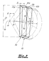
- Fig. 3 first illustrates the spherical shell section Design of the tubbing ring end faces 6, 7. Shown are two tubbing rings 1a, 1b, each one Ring width b and an outer diameter D.
- the rear segment ring face 7a of the first segment ring 1a is assumed to be one "imaginary" sphere, its center M on the central axis m of the segment ring 1a. The diameter of this ball is much larger than the cross-section of the segment ring 1a or the tunnel tube.
- the rear segment ring face 7a lies on the spherical shell or on the spherical surface the sphere with the radius R.
- Fig. 4 shows a plurality of one behind the other Segment rings 1.
- These segment rings 1 are all offset or rotated to each other so that there is a curved tunnel expansion, which in the exemplary embodiment corresponds to a 90 ° bend.
- Relocated or twisted arrangement of the tubbing rings 1 means, moreover, that the tubbing ring end faces 6, 7 of two neighboring ones Tubbing rings 1 do not lie completely flat against one another, but that only part of the segment ring end faces 6, 7 is form-fitting to each other.
Landscapes
- Engineering & Computer Science (AREA)
- Architecture (AREA)
- Structural Engineering (AREA)
- Mining & Mineral Resources (AREA)
- Civil Engineering (AREA)
- Life Sciences & Earth Sciences (AREA)
- General Life Sciences & Earth Sciences (AREA)
- Geochemistry & Mineralogy (AREA)
- Geology (AREA)
- Lining And Supports For Tunnels (AREA)
- Superconductors And Manufacturing Methods Therefor (AREA)
Abstract
Description
wobei eine vorderseitige Tübbingstirnfläche und eine rückseitige Tübbingstirnfläche vorgesehen ist,
und wobei zumindest eine Tübbingstirnfläche kugelschalenabschnittsförmig ausgebildet ist. - Tübbingstirnfläche meint im Rahmen der Erfindung eine Stirnfläche eines Tübbings, die im Tunnel bzw. im Tunnelausbau einem benachbarten Tübbingring zugewandt ist.
wobei jeder Tübbingring eine vorderseitige kugelschalenabschnittsförmige Tübbingringstirnfläche sowie eine rückseitige kugelschalenabschnittsförmige Tübbingringstirnfläche aufweist
und wobei die vorderseitige kugelschalenabschnittsförmige Tübbingringstirnfläche eines ersten Tübbingringes formschlüssig an die rückseitige kugelschalenabschnittsförmige Tübbingringstirnfläche eines zweiten benachbarten Tübbingringes angefügt ist.
- Fig. 1
- eine perspektivische Ansicht eines erfindungsgemäßen Tübbingringes,
- Fig. 2
- eine Seitenansicht auf den Gegenstand nach Fig. 1,
- Fig. 3
- eine schematische Veranschaulichung der Ausbildung und des Versatzes zweier hintereinander angeordneter Tübbingringe, und
- Fig. 4
- eine schematische Darstellung einer Mehrzahl in einem kurvenförmigen Tunnelabschnitt hintereinander angeordneter Tübbingringe.
Claims (8)
- Tübbing (2) für einen Tübbingring (1) zum unterirdischen Tunnelausbau,
wobei eine vorderseitige Tübbingstirnfläche (4) und eine rückseitige Tübbingstirnfläche (5) vorgesehen ist
und wobei zumindest eine Tübbingstirnfläche (4, 5) kugelschalenabschnittsförmig ausgebildet ist. - Tübbing nach Anspruch 1, wobei sowohl die vorderseitige Tübbingstirnfläche (4) als auch die rückseitige Tübbingstirnfläche (5) kugelschalenabschnittsförmig ausgebildet ist.
- Tübbing nach einem der Ansprüche 1 oder 2, wobei der Tübbing einen zylindermantelabschnittsförmigen Basiskörper aufweist.
- Tübbingring aus einer Mehrzahl von Tübbings (2) nach einem der Ansprüche 1 bis 3,
wobei eine vorderseitige Tübbingringstirnfläche (6) und eine rückseitige Tübbingringstirnfläche (7) vorgesehen ist,
und wobei zumindest eine Tübbingringstirnfläche (6, 7) kugelschalenabschnittsförmig ausgebildet ist. - Tübbingring nach Anspruch 4, wobei sowohl die vorderseitige Tübbingringstirnfläche (6) als auch die rückseitige Tübbingringstirnfläche (7) kugelschalenabschnittsförmig ausgebildet ist.
- Tübbingring nach einem der Ansprüche 4 oder 5, wobei der Mittelpunkt (M) der der kugelschalenabschnittsförmigen Tübbingringstirnfläche (6, 7) zugeordneten Kugel auf der Mittelachse (m) des Tübbingringes (1) angeordnet ist.
- Tübbingring nach einem der Ansprüche 4 bis 6, wobei fünf bis neun, vorzugsweise sechs bis acht Tübbings (2) zum Tübbingring (1) zusammengesetzt sind.
- Tunnelausbau mit einer Mehrzahl von in Tunnellängsrichtung hintereinander angeordneten Tübbingringen (1) nach einem der Ansprüche 4 bis 7,
wobei jeder Tübbingring (1) eine vorderseitige kugelschalenabschnittsförmige Tübbingringstirnfläche (6) sowie eine rückseitige kugelschalenabschnittsförmige Tübbingringstirnfläche (7) aufweist
und wobei die vorderseitige kugelschalenabschnittsförmige Tübbingringstirnfläche (6) eines ersten Tübbingringes (1) formschlüssig an die rückseitige kugelschalenabschnittsförmige Tübbingringstirnfläche (7) eines zweiten benachbarten Tübbingringes (1) angefügt ist.
Applications Claiming Priority (2)
| Application Number | Priority Date | Filing Date | Title |
|---|---|---|---|
| DE10129477 | 2001-06-21 | ||
| DE10129477A DE10129477C1 (de) | 2001-06-21 | 2001-06-21 | Tübbing, Tübbingring und Tunnelausbau |
Publications (2)
| Publication Number | Publication Date |
|---|---|
| EP1270871A1 true EP1270871A1 (de) | 2003-01-02 |
| EP1270871B1 EP1270871B1 (de) | 2006-05-17 |
Family
ID=7688656
Family Applications (1)
| Application Number | Title | Priority Date | Filing Date |
|---|---|---|---|
| EP02012026A Expired - Lifetime EP1270871B1 (de) | 2001-06-21 | 2002-05-31 | Tübbing, Tübbingring und Tunnelausbau |
Country Status (6)
| Country | Link |
|---|---|
| US (1) | US20040197151A1 (de) |
| EP (1) | EP1270871B1 (de) |
| AT (1) | ATE326615T1 (de) |
| DE (2) | DE10129477C1 (de) |
| ES (1) | ES2263705T3 (de) |
| WO (1) | WO2003001033A1 (de) |
Families Citing this family (1)
| Publication number | Priority date | Publication date | Assignee | Title |
|---|---|---|---|---|
| DE102009057521B4 (de) * | 2009-12-10 | 2011-07-21 | Bochumer Eisenhütte Heintzmann GmbH & Co. KG, 44793 | Tübbing-Ausbau mit integriertem Nachgiebigkeitselement |
Citations (7)
| Publication number | Priority date | Publication date | Assignee | Title |
|---|---|---|---|---|
| GB840262A (en) * | 1957-10-11 | 1960-07-06 | Vernon Ferdinand Bartlett | Improvements in or relating to tunnel linings |
| DE1811608A1 (de) | 1968-11-29 | 1970-06-11 | Wayss & Freytag Ag | Tuebbingauskleidung fuer Tunnel oder Stollen |
| DE3125274A1 (de) * | 1981-06-24 | 1983-01-13 | Philipp Holzmann Ag, 6000 Frankfurt | Rohre fuer kurvenfoermige tunnel, sowie verfahren zum bau kurvenfoermiger tunnel |
| GB2176865A (en) * | 1985-06-27 | 1987-01-07 | British Steel Corp | Pipe having a segmented lining |
| GB2194307A (en) * | 1986-07-09 | 1988-03-02 | Zueblin Ag | Pipe jocking conduits or tubular rings |
| DE3826833A1 (de) * | 1988-08-06 | 1990-02-08 | Ruhrkohle Ag | Anker-paneel-ausbau fuer untertagestrecken |
| DE19617200A1 (de) | 1996-04-29 | 1997-10-30 | Hochtief Ag Hoch Tiefbauten | Tunnelauskleidung |
Family Cites Families (12)
| Publication number | Priority date | Publication date | Assignee | Title |
|---|---|---|---|---|
| US739969A (en) * | 1901-02-25 | 1903-09-29 | Eddy Elbert Young | Tunnel-support. |
| US1198554A (en) * | 1915-03-30 | 1916-09-19 | Jacob Jarvey | Culvert. |
| US1613461A (en) * | 1926-06-01 | 1927-01-04 | Edwin A Johnson | Connection between well-pipe sections of different materials |
| GB2003212B (en) * | 1977-08-16 | 1982-01-13 | Charcon Tunnels Ltd | Arcuate tunnel lining segments |
| USRE30929E (en) * | 1977-09-28 | 1982-05-11 | Collapsible tunnel liner section and method of lining a tunnel | |
| US4473322A (en) * | 1979-05-07 | 1984-09-25 | Echols H Vance | Method and system for lining shafts |
| US4515501A (en) * | 1981-12-15 | 1985-05-07 | Fairclough Civil Engineering Limited | Tunnel linings |
| AT389149B (de) * | 1986-12-23 | 1989-10-25 | Mayreder Kraus & Co Ing | Tuebbingring fuer den stollen- und tunnelausbau |
| AT397543B (de) * | 1992-02-21 | 1994-04-25 | Mayreder Kraus & Co Ing | Tunnelausbau in tübbingbauweise |
| GB9322603D0 (en) * | 1993-11-02 | 1993-12-22 | Buchan C V Ltd | Device for jointing two members together |
| US5740839A (en) * | 1997-03-25 | 1998-04-21 | Kuo; Hsien-Jen | Flexible extension conduit |
| AU728611B2 (en) * | 1997-08-13 | 2001-01-11 | Obayashi Corporation | Segment for a water intake tunnel |
-
2001
- 2001-06-21 DE DE10129477A patent/DE10129477C1/de not_active Expired - Fee Related
-
2002
- 2002-05-31 DE DE50206781T patent/DE50206781D1/de not_active Expired - Fee Related
- 2002-05-31 AT AT02012026T patent/ATE326615T1/de not_active IP Right Cessation
- 2002-05-31 ES ES02012026T patent/ES2263705T3/es not_active Expired - Lifetime
- 2002-05-31 EP EP02012026A patent/EP1270871B1/de not_active Expired - Lifetime
- 2002-06-15 US US10/481,540 patent/US20040197151A1/en not_active Abandoned
- 2002-06-15 WO PCT/EP2002/006619 patent/WO2003001033A1/de not_active Ceased
Patent Citations (8)
| Publication number | Priority date | Publication date | Assignee | Title |
|---|---|---|---|---|
| GB840262A (en) * | 1957-10-11 | 1960-07-06 | Vernon Ferdinand Bartlett | Improvements in or relating to tunnel linings |
| DE1811608A1 (de) | 1968-11-29 | 1970-06-11 | Wayss & Freytag Ag | Tuebbingauskleidung fuer Tunnel oder Stollen |
| DE3125274A1 (de) * | 1981-06-24 | 1983-01-13 | Philipp Holzmann Ag, 6000 Frankfurt | Rohre fuer kurvenfoermige tunnel, sowie verfahren zum bau kurvenfoermiger tunnel |
| GB2176865A (en) * | 1985-06-27 | 1987-01-07 | British Steel Corp | Pipe having a segmented lining |
| GB2194307A (en) * | 1986-07-09 | 1988-03-02 | Zueblin Ag | Pipe jocking conduits or tubular rings |
| DE3826833A1 (de) * | 1988-08-06 | 1990-02-08 | Ruhrkohle Ag | Anker-paneel-ausbau fuer untertagestrecken |
| DE19617200A1 (de) | 1996-04-29 | 1997-10-30 | Hochtief Ag Hoch Tiefbauten | Tunnelauskleidung |
| EP0805261A1 (de) * | 1996-04-29 | 1997-11-05 | Hochtief Aktiengesellschaft Vorm. Gebr. Helfmann | Tunnelauskleidung |
Also Published As
| Publication number | Publication date |
|---|---|
| US20040197151A1 (en) | 2004-10-07 |
| DE10129477C1 (de) | 2002-08-29 |
| ES2263705T3 (es) | 2006-12-16 |
| WO2003001033A1 (de) | 2003-01-03 |
| EP1270871B1 (de) | 2006-05-17 |
| DE50206781D1 (de) | 2006-06-22 |
| ATE326615T1 (de) | 2006-06-15 |
Similar Documents
| Publication | Publication Date | Title |
|---|---|---|
| WO2020160582A1 (de) | Tübbing aus bewehrtem beton | |
| DE102009028306B4 (de) | Doppelrohr | |
| DE2003197A1 (de) | Waermetauscher | |
| DE2637726C3 (de) | Streckenausbaurahmen | |
| DE2913519C3 (de) | Flexible Rohrleitung | |
| EP1270871B1 (de) | Tübbing, Tübbingring und Tunnelausbau | |
| DE2743639A1 (de) | Mit flexiblem stab armierte betonstuetze und verfahren zur herstellung derselben | |
| DE3151845A1 (de) | Wellrohr mit zugentlastung und verfahren zu dessen herstellung aus kunststoff | |
| DE102009057521A1 (de) | Tübbing-Ausbau mit integriertem Nachgiebigkeitselement | |
| EP3921514B1 (de) | Tübbing aus bewehrtem beton | |
| DE102013003859A1 (de) | Gleichlaufgelenk | |
| DE3622965C1 (de) | Vorgefertigtes Rohr oder vorgefertigter Rohrring | |
| DE3125274C2 (de) | Verfahren zum Bau von kurvenförmig verlaufenden Tunneln nach dem Rohrvorpreßverfahren und dazu geeignete Rohre | |
| DE19616143C1 (de) | Tunnelauskleidung mit in Tunnellängsrichtung hintereinander angeordneten Tübbingringen | |
| EP3070205A1 (de) | Gründungspfahl für eine windenergieanlage | |
| DE10119988B4 (de) | Verdübelungs-Vorrichtung für die Ringelemente einer Tübbingauskleidung für unterirdische Bauwerke | |
| DE2545353A1 (de) | Rohranschlussmuffe | |
| DE2430026C2 (de) | Gleichlaufdrehgelenk mit Wälzkörpern zur Drehmomentübertragung | |
| DE3247641A1 (de) | Gittertraeger | |
| DE2412459C3 (de) | Bewehrungselement für einen Verpreßanker | |
| DE2945554A1 (de) | Rohrkupplung fuer in rohrschuesse unterteilte rammrohre | |
| DE3544884C2 (de) | Biegbarer Hochdruck-Metall-Ringwellschlauch | |
| CH537504A (de) | Abstandhalter für Eisenbetonstäbe | |
| DE102017209651A1 (de) | Distanzstück für ein Rollenlager und Rollenlager mit einem solchen Distanzstück | |
| DE2022403A1 (de) | Huelsenkupplung |
Legal Events
| Date | Code | Title | Description |
|---|---|---|---|
| PUAI | Public reference made under article 153(3) epc to a published international application that has entered the european phase |
Free format text: ORIGINAL CODE: 0009012 |
|
| 17P | Request for examination filed |
Effective date: 20021012 |
|
| AK | Designated contracting states |
Kind code of ref document: A1 Designated state(s): AT BE CH CY DE DK ES FI FR GB GR IE IT LI LU MC NL PT SE TR |
|
| AX | Request for extension of the european patent |
Free format text: AL;LT;LV;MK;RO;SI |
|
| AKX | Designation fees paid |
Designated state(s): AT BE CH CY DE DK ES FI FR GB GR IE IT LI LU MC NL PT SE TR |
|
| GRAP | Despatch of communication of intention to grant a patent |
Free format text: ORIGINAL CODE: EPIDOSNIGR1 |
|
| GRAS | Grant fee paid |
Free format text: ORIGINAL CODE: EPIDOSNIGR3 |
|
| GRAA | (expected) grant |
Free format text: ORIGINAL CODE: 0009210 |
|
| AK | Designated contracting states |
Kind code of ref document: B1 Designated state(s): AT BE CH CY DE DK ES FI FR GB GR IE IT LI LU MC NL PT SE TR |
|
| PG25 | Lapsed in a contracting state [announced via postgrant information from national office to epo] |
Ref country code: IT Free format text: LAPSE BECAUSE OF FAILURE TO SUBMIT A TRANSLATION OF THE DESCRIPTION OR TO PAY THE FEE WITHIN THE PRESCRIBED TIME-LIMIT;WARNING: LAPSES OF ITALIAN PATENTS WITH EFFECTIVE DATE BEFORE 2007 MAY HAVE OCCURRED AT ANY TIME BEFORE 2007. THE CORRECT EFFECTIVE DATE MAY BE DIFFERENT FROM THE ONE RECORDED. Effective date: 20060517 Ref country code: IE Free format text: LAPSE BECAUSE OF FAILURE TO SUBMIT A TRANSLATION OF THE DESCRIPTION OR TO PAY THE FEE WITHIN THE PRESCRIBED TIME-LIMIT Effective date: 20060517 Ref country code: FI Free format text: LAPSE BECAUSE OF FAILURE TO SUBMIT A TRANSLATION OF THE DESCRIPTION OR TO PAY THE FEE WITHIN THE PRESCRIBED TIME-LIMIT Effective date: 20060517 |
|
| REG | Reference to a national code |
Ref country code: GB Ref legal event code: FG4D Free format text: NOT ENGLISH |
|
| PG25 | Lapsed in a contracting state [announced via postgrant information from national office to epo] |
Ref country code: BE Free format text: LAPSE BECAUSE OF NON-PAYMENT OF DUE FEES Effective date: 20060531 Ref country code: MC Free format text: LAPSE BECAUSE OF NON-PAYMENT OF DUE FEES Effective date: 20060531 |
|
| REG | Reference to a national code |
Ref country code: CH Ref legal event code: EP |
|
| PGFP | Annual fee paid to national office [announced via postgrant information from national office to epo] |
Ref country code: GB Payment date: 20060612 Year of fee payment: 5 |
|
| PGFP | Annual fee paid to national office [announced via postgrant information from national office to epo] |
Ref country code: NL Payment date: 20060614 Year of fee payment: 5 |
|
| REG | Reference to a national code |
Ref country code: IE Ref legal event code: FG4D Free format text: LANGUAGE OF EP DOCUMENT: GERMAN |
|
| REF | Corresponds to: |
Ref document number: 50206781 Country of ref document: DE Date of ref document: 20060622 Kind code of ref document: P |
|
| REG | Reference to a national code |
Ref country code: CH Ref legal event code: NV Representative=s name: KELLER & PARTNER PATENTANWAELTE AG |
|
| PG25 | Lapsed in a contracting state [announced via postgrant information from national office to epo] |
Ref country code: SE Free format text: LAPSE BECAUSE OF FAILURE TO SUBMIT A TRANSLATION OF THE DESCRIPTION OR TO PAY THE FEE WITHIN THE PRESCRIBED TIME-LIMIT Effective date: 20060817 Ref country code: DK Free format text: LAPSE BECAUSE OF FAILURE TO SUBMIT A TRANSLATION OF THE DESCRIPTION OR TO PAY THE FEE WITHIN THE PRESCRIBED TIME-LIMIT Effective date: 20060817 |
|
| GBT | Gb: translation of ep patent filed (gb section 77(6)(a)/1977) |
Effective date: 20060801 |
|
| PG25 | Lapsed in a contracting state [announced via postgrant information from national office to epo] |
Ref country code: PT Free format text: LAPSE BECAUSE OF FAILURE TO SUBMIT A TRANSLATION OF THE DESCRIPTION OR TO PAY THE FEE WITHIN THE PRESCRIBED TIME-LIMIT Effective date: 20061017 |
|
| REG | Reference to a national code |
Ref country code: ES Ref legal event code: FG2A Ref document number: 2263705 Country of ref document: ES Kind code of ref document: T3 |
|
| REG | Reference to a national code |
Ref country code: IE Ref legal event code: FD4D |
|
| PLBE | No opposition filed within time limit |
Free format text: ORIGINAL CODE: 0009261 |
|
| STAA | Information on the status of an ep patent application or granted ep patent |
Free format text: STATUS: NO OPPOSITION FILED WITHIN TIME LIMIT |
|
| 26N | No opposition filed |
Effective date: 20070220 |
|
| EN | Fr: translation not filed | ||
| BERE | Be: lapsed |
Owner name: HOCHTIEF A.G. Effective date: 20060531 |
|
| GBPC | Gb: european patent ceased through non-payment of renewal fee |
Effective date: 20070531 |
|
| PG25 | Lapsed in a contracting state [announced via postgrant information from national office to epo] |
Ref country code: NL Free format text: LAPSE BECAUSE OF NON-PAYMENT OF DUE FEES Effective date: 20071201 |
|
| NLV4 | Nl: lapsed or anulled due to non-payment of the annual fee |
Effective date: 20071201 |
|
| PG25 | Lapsed in a contracting state [announced via postgrant information from national office to epo] |
Ref country code: FR Free format text: LAPSE BECAUSE OF FAILURE TO SUBMIT A TRANSLATION OF THE DESCRIPTION OR TO PAY THE FEE WITHIN THE PRESCRIBED TIME-LIMIT Effective date: 20070309 Ref country code: GR Free format text: LAPSE BECAUSE OF FAILURE TO SUBMIT A TRANSLATION OF THE DESCRIPTION OR TO PAY THE FEE WITHIN THE PRESCRIBED TIME-LIMIT Effective date: 20060818 |
|
| PG25 | Lapsed in a contracting state [announced via postgrant information from national office to epo] |
Ref country code: GB Free format text: LAPSE BECAUSE OF NON-PAYMENT OF DUE FEES Effective date: 20070531 |
|
| PG25 | Lapsed in a contracting state [announced via postgrant information from national office to epo] |
Ref country code: LU Free format text: LAPSE BECAUSE OF NON-PAYMENT OF DUE FEES Effective date: 20060531 Ref country code: TR Free format text: LAPSE BECAUSE OF FAILURE TO SUBMIT A TRANSLATION OF THE DESCRIPTION OR TO PAY THE FEE WITHIN THE PRESCRIBED TIME-LIMIT Effective date: 20060517 |
|
| PG25 | Lapsed in a contracting state [announced via postgrant information from national office to epo] |
Ref country code: FR Free format text: LAPSE BECAUSE OF FAILURE TO SUBMIT A TRANSLATION OF THE DESCRIPTION OR TO PAY THE FEE WITHIN THE PRESCRIBED TIME-LIMIT Effective date: 20060531 |
|
| PG25 | Lapsed in a contracting state [announced via postgrant information from national office to epo] |
Ref country code: FR Free format text: LAPSE BECAUSE OF FAILURE TO SUBMIT A TRANSLATION OF THE DESCRIPTION OR TO PAY THE FEE WITHIN THE PRESCRIBED TIME-LIMIT Effective date: 20060517 Ref country code: CY Free format text: LAPSE BECAUSE OF FAILURE TO SUBMIT A TRANSLATION OF THE DESCRIPTION OR TO PAY THE FEE WITHIN THE PRESCRIBED TIME-LIMIT Effective date: 20060517 |
|
| PGFP | Annual fee paid to national office [announced via postgrant information from national office to epo] |
Ref country code: ES Payment date: 20090521 Year of fee payment: 8 |
|
| PGFP | Annual fee paid to national office [announced via postgrant information from national office to epo] |
Ref country code: AT Payment date: 20090528 Year of fee payment: 8 Ref country code: DE Payment date: 20090512 Year of fee payment: 8 |
|
| PGFP | Annual fee paid to national office [announced via postgrant information from national office to epo] |
Ref country code: CH Payment date: 20090518 Year of fee payment: 8 |
|
| REG | Reference to a national code |
Ref country code: CH Ref legal event code: PL |
|
| PG25 | Lapsed in a contracting state [announced via postgrant information from national office to epo] |
Ref country code: AT Free format text: LAPSE BECAUSE OF NON-PAYMENT OF DUE FEES Effective date: 20100531 |
|
| PG25 | Lapsed in a contracting state [announced via postgrant information from national office to epo] |
Ref country code: LI Free format text: LAPSE BECAUSE OF NON-PAYMENT OF DUE FEES Effective date: 20100531 Ref country code: CH Free format text: LAPSE BECAUSE OF NON-PAYMENT OF DUE FEES Effective date: 20100531 |
|
| PG25 | Lapsed in a contracting state [announced via postgrant information from national office to epo] |
Ref country code: DE Free format text: LAPSE BECAUSE OF NON-PAYMENT OF DUE FEES Effective date: 20101201 |
|
| REG | Reference to a national code |
Ref country code: ES Ref legal event code: FD2A Effective date: 20110714 |
|
| PG25 | Lapsed in a contracting state [announced via postgrant information from national office to epo] |
Ref country code: ES Free format text: LAPSE BECAUSE OF NON-PAYMENT OF DUE FEES Effective date: 20110704 |
|
| PG25 | Lapsed in a contracting state [announced via postgrant information from national office to epo] |
Ref country code: ES Free format text: LAPSE BECAUSE OF NON-PAYMENT OF DUE FEES Effective date: 20100601 |