EP1270455A1 - Verfahren und Vorrichtung zur Montage und Verpackung kleinstueckiger Artikel - Google Patents
Verfahren und Vorrichtung zur Montage und Verpackung kleinstueckiger Artikel Download PDFInfo
- Publication number
- EP1270455A1 EP1270455A1 EP02011076A EP02011076A EP1270455A1 EP 1270455 A1 EP1270455 A1 EP 1270455A1 EP 02011076 A EP02011076 A EP 02011076A EP 02011076 A EP02011076 A EP 02011076A EP 1270455 A1 EP1270455 A1 EP 1270455A1
- Authority
- EP
- European Patent Office
- Prior art keywords
- component
- components
- input
- packaging
- adhesive
- Prior art date
- Legal status (The legal status is an assumption and is not a legal conclusion. Google has not performed a legal analysis and makes no representation as to the accuracy of the status listed.)
- Granted
Links
- 238000000034 method Methods 0.000 title claims abstract description 41
- 238000012856 packing Methods 0.000 title description 4
- 239000000853 adhesive Substances 0.000 claims abstract description 39
- 230000001070 adhesive effect Effects 0.000 claims abstract description 39
- 238000004806 packaging method and process Methods 0.000 claims description 50
- 238000011156 evaluation Methods 0.000 claims description 12
- 230000003287 optical effect Effects 0.000 claims description 8
- 230000001360 synchronised effect Effects 0.000 claims description 6
- 238000012546 transfer Methods 0.000 claims description 4
- 238000010191 image analysis Methods 0.000 claims description 3
- 239000002245 particle Substances 0.000 claims description 3
- 239000000969 carrier Substances 0.000 claims description 2
- 238000001514 detection method Methods 0.000 claims description 2
- 238000003860 storage Methods 0.000 claims description 2
- 238000011144 upstream manufacturing Methods 0.000 claims description 2
- 238000007689 inspection Methods 0.000 claims 1
- 238000012544 monitoring process Methods 0.000 claims 1
- 238000000926 separation method Methods 0.000 description 7
- 238000003908 quality control method Methods 0.000 description 6
- 238000013461 design Methods 0.000 description 3
- 230000015572 biosynthetic process Effects 0.000 description 2
- 238000009434 installation Methods 0.000 description 2
- 238000005304 joining Methods 0.000 description 2
- 238000012858 packaging process Methods 0.000 description 2
- 238000003825 pressing Methods 0.000 description 2
- 238000012545 processing Methods 0.000 description 2
- 102100026827 Protein associated with UVRAG as autophagy enhancer Human genes 0.000 description 1
- 101710102978 Protein associated with UVRAG as autophagy enhancer Proteins 0.000 description 1
- 238000004026 adhesive bonding Methods 0.000 description 1
- 239000011248 coating agent Substances 0.000 description 1
- 238000000576 coating method Methods 0.000 description 1
- 238000010276 construction Methods 0.000 description 1
- 230000002950 deficient Effects 0.000 description 1
- 230000001419 dependent effect Effects 0.000 description 1
- 239000000428 dust Substances 0.000 description 1
- 230000000694 effects Effects 0.000 description 1
- 238000001914 filtration Methods 0.000 description 1
- 238000002955 isolation Methods 0.000 description 1
- 239000000463 material Substances 0.000 description 1
- 238000012360 testing method Methods 0.000 description 1
- 238000011179 visual inspection Methods 0.000 description 1
Images


Classifications
-
- B—PERFORMING OPERATIONS; TRANSPORTING
- B23—MACHINE TOOLS; METAL-WORKING NOT OTHERWISE PROVIDED FOR
- B23P—METAL-WORKING NOT OTHERWISE PROVIDED FOR; COMBINED OPERATIONS; UNIVERSAL MACHINE TOOLS
- B23P19/00—Machines for simply fitting together or separating metal parts or objects, or metal and non-metal parts, whether or not involving some deformation; Tools or devices therefor so far as not provided for in other classes
- B23P19/008—Machines for simply fitting together or separating metal parts or objects, or metal and non-metal parts, whether or not involving some deformation; Tools or devices therefor so far as not provided for in other classes the parts being continuously transported through the machine during assembling or disassembling
-
- B—PERFORMING OPERATIONS; TRANSPORTING
- B23—MACHINE TOOLS; METAL-WORKING NOT OTHERWISE PROVIDED FOR
- B23P—METAL-WORKING NOT OTHERWISE PROVIDED FOR; COMBINED OPERATIONS; UNIVERSAL MACHINE TOOLS
- B23P19/00—Machines for simply fitting together or separating metal parts or objects, or metal and non-metal parts, whether or not involving some deformation; Tools or devices therefor so far as not provided for in other classes
- B23P19/04—Machines for simply fitting together or separating metal parts or objects, or metal and non-metal parts, whether or not involving some deformation; Tools or devices therefor so far as not provided for in other classes for assembling or disassembling parts
-
- Y—GENERAL TAGGING OF NEW TECHNOLOGICAL DEVELOPMENTS; GENERAL TAGGING OF CROSS-SECTIONAL TECHNOLOGIES SPANNING OVER SEVERAL SECTIONS OF THE IPC; TECHNICAL SUBJECTS COVERED BY FORMER USPC CROSS-REFERENCE ART COLLECTIONS [XRACs] AND DIGESTS
- Y10—TECHNICAL SUBJECTS COVERED BY FORMER USPC
- Y10T—TECHNICAL SUBJECTS COVERED BY FORMER US CLASSIFICATION
- Y10T29/00—Metal working
- Y10T29/49—Method of mechanical manufacture
- Y10T29/49826—Assembling or joining
- Y10T29/49828—Progressively advancing of work assembly station or assembled portion of work
- Y10T29/49829—Advancing work to successive stations [i.e., assembly line]
-
- Y—GENERAL TAGGING OF NEW TECHNOLOGICAL DEVELOPMENTS; GENERAL TAGGING OF CROSS-SECTIONAL TECHNOLOGIES SPANNING OVER SEVERAL SECTIONS OF THE IPC; TECHNICAL SUBJECTS COVERED BY FORMER USPC CROSS-REFERENCE ART COLLECTIONS [XRACs] AND DIGESTS
- Y10—TECHNICAL SUBJECTS COVERED BY FORMER USPC
- Y10T—TECHNICAL SUBJECTS COVERED BY FORMER US CLASSIFICATION
- Y10T29/00—Metal working
- Y10T29/53—Means to assemble or disassemble
- Y10T29/53313—Means to interrelatedly feed plural work parts from plural sources without manual intervention
- Y10T29/53374—Means to interrelatedly feed plural work parts from plural sources without manual intervention including turret-type conveyor
-
- Y—GENERAL TAGGING OF NEW TECHNOLOGICAL DEVELOPMENTS; GENERAL TAGGING OF CROSS-SECTIONAL TECHNOLOGIES SPANNING OVER SEVERAL SECTIONS OF THE IPC; TECHNICAL SUBJECTS COVERED BY FORMER USPC CROSS-REFERENCE ART COLLECTIONS [XRACs] AND DIGESTS
- Y10—TECHNICAL SUBJECTS COVERED BY FORMER USPC
- Y10T—TECHNICAL SUBJECTS COVERED BY FORMER US CLASSIFICATION
- Y10T29/00—Metal working
- Y10T29/53—Means to assemble or disassemble
- Y10T29/534—Multiple station assembly or disassembly apparatus
- Y10T29/53404—Multiple station assembly or disassembly apparatus including turret-type conveyor
Definitions
- the present invention relates to a method and an apparatus for assembly and packaging small items according to the preambles of the claims 1 and 15.
- Such a device is known from EP 1 048 569 A2, a first Component of an article consisting of two components by a conveyor belt without spacing and along a linear transport direction second conveyor is supplied.
- the second conveyor has one endless chain, guided on two sprockets, one lower driver to take the first component and an upper driver to take along the second component are attached to the chain.
- a spacing from the first Components are made using the lower drivers.
- the top drivers have cutouts for receiving the second components.
- An alignment the first and the second component relative to each other is represented by a Arrangement of the lower and upper drivers realized.
- the aligned to each other first and second components are conveyed by a third conveyor, which pressing means for connecting the first and second components has added to an article.
- the invention is therefore based on the object of a method for assembly and Specify packaging of small items with which one item from several Components with gentle treatment of the article and the individual Components can be assembled and fed to a packaging facility.
- the second component is preferably cohesive with the first component way connected.
- evaluation criteria are: the presence of both components in the article, a location of the second components in a recess of the first component and one The integrity of the first component and the second component is used.
- the invention is further based on the object of a device for Assembly and packaging of at least two components to create small pieces, being a compact design with simultaneous gentle handling of the components and the articles and a high Machine performance is made possible.
- the assembly and packaging device is characterized in As part of a continuous assembly and packaging process that the assembly of the article by a movable, in particular rotating Assembly head is performed, both the first component as the second component can also be fed separately to this assembly head.
- the following is a procedure for assembling and packaging small items A from at least two components K1, K2 and a device for assembly and packaging of at least two components K1, K2, small-piece articles A according to preferred embodiments with reference to the figures 1 to 4 explained, the device in the present Case designed for mounting and packaging a dishwasher tab is without being limited to this.
- An outer contour of an article A Assembled components K1, K2 can accordingly be freely selected without essential Changes to the method or the device are necessary.
- a dishwasher tab becomes an article A from a prismatic shaped body, in particular a cuboid with a shape for at least partial inclusion a second component K2 is formed.
- the second component K2 is preferred rotationally symmetrical.
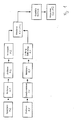
- FIG. 1 schematically shows a procedure for separately feeding the first one and the second component K1, K2, the assembly of the first and second Component K1, K2 formed article A, a quality control of the article A and a packaging of the articles A are shown in a joining and packaging process.
- the items are preferably packaged in a flow pack machine.
- Packaging small items A from at least two components K1, K2 will be the first component K1 before assembling the article A. fed to the process and synchronized, with synchronizing preferred in this Embodiment spacing on a division and arrange in one determined, relative position, in particular to an input chain of the device for assembly and packaging of at least two components each K1, K2 existing small items A means.
- the synchronized first components K1 are preferably in the range the formation for at least partially accommodating a second component Provide K2 with an adhesive application ("glued").
- Such a coating with an adhesive is advantageous for a connection between the first and the second component K1, K2, however, not mandatory for the method described, and accordingly is the one described Procedures are not limited to this.
- An assembly of the first and second Component K1, K2 existing small-piece article A can for example also by only pressing the second component K2 into the recess the first component K1.
- a small item A with insufficient Adhesive application is carried out according to a further preferred embodiment sorted out in the further course of the process.
- a sorting can be done can take place at various points in the course of the method, for example a first component K1 with insufficient adhesive application an assembly with a second component K2 and thus before the packaging step be sorted out.
- the first components K1 independently of one Assessment of the adhesive application fed to the assembly process.
- a sorting out of articles with insufficient adhesive application is done before packaging the assembled item.
- the stored second component K2 is after that described in Fig. 1 preferred method for assembling and packaging small items A from at least two components K1, K2 the process after a sorting step fed and isolated.
- the isolated second component K2 is glued to the first component K1 merged and assembled into an article A ("K1 + K2"). After a downstream quality control are the requirements of quality control enough item A packed.
- Fig. 2 shows a schematic representation of part of a device for Assembly and packaging of at least two components each small items A.
- the device consists essentially of a Feeding and synchronizing device not shown here with a Input chain 14 with side guides 15 for the first component K1, one Adhesive supply device for the first component K1 including one Test system for a sufficient application of adhesive, a storage and feeding device for the second component K2, a handling device 1 for Assembly of Article A, an image processing system for quality control of the Article A, and a packaging machine (not shown) for packaging the tested Article A preferably in flow packs.
- the first components K1 become the device for assembly and packaging of small pieces consisting of at least two components K1, K2 Articles A arranged in a row on a conveyor belt, not shown here fed and jammed on a conveyor belt of the feed and synchronization system.
- the first components K1 are then synchronized, that is to say a division spaced and in a certain, relative position to the input chain 14 of the device for assembly and packaging from at least each two components K1, K2 existing small pieces A arranged, so that the first components K1 of drivers (not shown) of the input chain 14 can be taken over, with a lateral guidance of the first components K1 by means of side guides 15.
- the lateral guidance of the first Component K1 only starts after the first components of the Carriers of the input chain 14 were taken over.
- the first components K1 of the drivers of the input chain 14 in an input wheel 4 have a precisely definable position.
- the first component K1 is an adhesive application and in the preferred one Embodiment also a check of the adhesive application preferably in Area of the input chain 14 or in the area of the input wheel 4 feasible. Due to the better accessibility in the area of the input chain 14 the preferably electrically actuated application head for the application of adhesive and also a control sensor for the application of adhesive, especially in the area of Input chain 14 arranged. Execution of the adhesive order and / or However, the control of the adhesive application is also more structural if there is a corresponding one Design without restrictions in the area of the input wheel 4 feasible.
- one is used to control an adhesive application necessary trigger signal generated by an optical sensor that it is provided to recognize an edge of the first component K1.
- the trigger signal of the optical sensor is made available to a route control device.
- a preferably electrically operated application head for the application of adhesive is by means of signals from the route control unit in conjunction with one on the drive the input chain 14 or the input wheel 4 installed incremental Pacer actuated.
- the first components K1 are cam-controlled from the input wheel 4 Pass gripper pairs 2 of an assembly head 12 to the handling device 1.
- the mounting head 12 is shown in more detail in FIGS. 2, 3 and 4.
- the second components K2 are from a belt bunker, not shown transported an elevator to a centrifugal conveyor, the elevator controlled by determining a level of the centrifugal conveyor becomes.
- the second components K2 pass from this centrifugal conveyor a feed device 11, in the preferred shown schematically in Fig. 4 Embodiment an inclined feed rail 16 to the mounting head 12.
- On the inclined feed rail 16 are sensors (not shown) for control of the centrifugal conveyor and to control the material flow at second Components K2 attached during operation of the device.
- the mounting head 12 has a separating plate 7 with pocket-shaped recesses 8 for receiving of the second component K2, with the separating plate 7 in the preferred embodiment is arranged interchangeably on the axis.
- the Isolation plate 7 is arranged adjacent to the inclined guide rail 16.
- the second components K2 are located in front of this separation plate 7 within the guide rail 16 in a traffic jam.
- the rotating with the mounting head 12 Separating plate 7 takes a second component K2 from this Traffic jam.
- a pneumatically operated stopper (Not shown) provided that a supply of the second components K2 to the mounting head 12, for example, depending on an operating state of the Assembly head 12 can interrupt. Based on signals from the inclined Feed rail 16 attached sensors can, for example, also System are shut down when there is a particle flow in the feed rail 16 is interrupted.
- the second components K2 are controlled by cam-controlled from the separating plate 7 Suction pad devices 13, in particular vertical suction pad devices 13 taken over.
- the suction stamp devices 13 have suction devices, at least in the area of the takeover of the second component K2 from the feed rail 16 until the second one is pressed in Component K2 in the recess 5 for receiving the second component K2 of the first component K2 by means of a central vacuum distributor 22 Vacuum are applied.
- This air filter 18 does not have a further exemplary embodiment, not shown on.
- the individual Suction pad devices 13 at least partially via individual feed lines connected to a vacuum source. Controlling an application of the Suction pad devices 13 with vacuum are preferred via a valve arrangement Solenoid valves, in particular in connection with throttle devices.
- the joined articles A are one at the delivery position Dispensing wheel 3 and from this a driving chain 20 which passes the article A a packaging machine, especially a flow pack machine (Tubular bag packaging machine).
- a packaging machine especially a flow pack machine (Tubular bag packaging machine).
- the evaluation criteria include at least the presence of both components in the article, a location of the second Component in the recess of the first component, an integrity of the first component and an integrity of the second component. Therefore If at least one of the mentioned characteristics is not met, the corresponding one is Item A removed from the system before packing.
- the articles A arrive in a position in the Flowpack machine formed film tube, which seals longitudinally and crosswise as well is separated, whereby the articles A are packed.
- the related sorting out defective article A will result in empty packs aspirated.
- a first component K1 becomes one Handling device 1 supplied, the first component K1 a second Assigned component K2.
- the one from the first and the second component K1, K2 assembled article A is then packed.
- the first component K1 is between an input and a delivery position by the handling device 1 held by controllable pairs of grippers 2 along a curved Path guided, the first components K1 at the input position recorded, guided along the curved path and at the delivery position from the gripper pairs 2 of the handling device 1 to a transfer device 3 are handed over.
- the second component K2 is also the Handling device 1 supplied, isolated and with the first component K1 connected.
- the first components K1 is preferably arranged in a row and arranged on a conveyor belt jammed on a conveyor belt of a feed and synchronization system and then synchronized with a division of an input device 4 and with each other handed over spaced.
- the first components K1 molded recesses 5 for receiving the second components K2 after synchronization with the input device 4 of the first components Apply an adhesive to K1.
- the adhesive is applied preferably depending on a position detection of the first component K1 by means of an optical sensor, in particular an edge sensor, for the first component K1 in connection with an incremental encoder, not shown.
- the application of adhesive can be checked, preferably by means of an infrared sensor, preferably small items with insufficient Adhesive application of the first component before packaging the small items are sorted out.
- the second component K2 is according to the preferred embodiment described essentially radially to the handling device 1 before connection supplied with the first component K1. In another, not shown In the exemplary embodiment, the second component K2 is fed to the handling device 1 essentially tangential.
- the supply of the second components K2 is preferably monitored by sensors, based on signals attached to the feed rail 16 Sensors the system is shut down when there is a particle flow in the feed rail 16 is interrupted.
- the second component K2 is made according to the method step described a jam in the feed 6 to the handling device 1 with a the handling device 1 revolving separation plate 7 in a pocket formed recesses 8 of the same and thus from the Occasional traffic jam. At least temporarily in contact with the second components K2 standing side surface of the separation plate 7 are preferably such shaped that the second components K2 are promoted quasi-continuously.
- the isolated second components K2 are preferably via a sucker 9 sucked in, inserted into the recess 5 of the first component K1 and inextricably linked with this. According to the preferred embodiment described the procedure for assembling and packaging small items A becomes a second component K2 in a recess 5 of a first Component K1 used.
- a control of article A before packaging using a plurality of evaluation criteria whereby an item is sorted out, if at least one of the evaluation criteria is not met.
- the preferred Optical control is preferably carried out by means of an image analysis.
- the evaluation criteria include at least the presence of both components K1, K2 in article A, a layer of the second component K2 in the recess 5 of the first component K1, an integrity of the first component K1 and the integrity of the second component K2.
- the Device for the assembly and packaging of at least two components each K1 and K2 existing, small-piece articles A a first feed device 10 for the first component K1, a second feed device 11 for the second component K2, a handling device 1 for connecting the first Component K1 with the second component K2, a relay device 3 of Article A and.
- Suction pad devices 13 are provided with a central vacuum distributor 22 connected.
- the device for mounting and packaging of at least two components K1 and K2, small items A an input wheel 4, the input wheel 4 is arranged upstream of the mounting head 12 and with one, a plurality of first components K1 to the input chain 4 feeding the input wheel 4 in Active connection is. Every first component K1 is in the process of transferring the first components K1 of drivers 15 of the input chain 14 to the input wheel 4 spaced, and is under precise positioning from the cam-controlled Gripper pairs 2 of the mounting head 12 can be picked up.
- An adhesive supply device for introducing an adhesive into a recess 5 each of the first components K1 is according to the described exemplary embodiments in the area of the input chain 14 or in the area of the input wheel 4 provided.
- For actuating an electrically operated application head for the application of adhesive is preferably one in the area of a drive (not shown) the input chain 14 or the input wheel 4 arranged position sensor, in particular an edge sensor with an incremental encoder (not shown), intended.
- each recess 5 of the first Component K1 is preferably one in the area of the input chain 14 or the Input wheel 4 arranged infrared sensor (not shown) is provided.
- a Ejection device for first components K1 after assembly with the second one Component and before packaging the assembled item A is described in the preferred embodiment of an output signal of the infrared sensor dependent.
- the second component K2 is a centrifugal conveyor according to this embodiment the device for assembly and packaging from at least Small components A consisting of two components K1 and K2 each a belt bunker can be fed via an elevator, the elevator depending is controllable from a filling level of the centrifugal conveyor.
- Sensors are connected to the feed rail 16 to monitor the supply of second components K2, to control the Centrifugal conveyor and the mounting head 12 are provided.
- the separation plate 7 is arranged interchangeably on the axis. Immediately in front of the separation plate 7 of the mounting head 12 is a pneumatically operated one in particular Stopper arranged, the stopper to interrupt a feed of the second components K2 to the mounting head 12 in particular depending on an operating state of the mounting head 12 is provided.
- a substantially vertical movement of the suction pad devices described 13, in particular vertical suction stamp devices 13 is preferred controllable by means of a cam disk 17.
- the cam 17 for Movement of the vertical suction stamp devices 13 is preferably interchangeable.
- a connection of the suction stamp devices 13 to the central vacuum distributor 22 has at least one according to the preferred embodiment Air filter 18 on.
- Air filter 18 One size of these air filters is due to the spatial conditions adapted to the installation location.
- a larger one is central Air filter (not shown) between vacuum manifold 22 and a vacuum generator Facility installed.
- This central air filter is of the structural type Conditions of the installation site are significantly less restricted, which means Soiling and clogging effects of the central air filter are significantly reduced are. It should be noted that in the packaging area of Dishwasher tabs have a very high dust load.
- the described preferred embodiment shows that a Dispensing wheel 3 is arranged downstream of the mounting head 12, the dispensing wheel 3 with one, leading a plurality of the articles A away from the delivery wheel 3 another drive chain 20 with side guides 21 is operatively connected.
- the Delivery wheel 3 transfers each article A to drivers (not shown) of the driver chain 20 spaced from a downstream packaging machine, the Driver chain 20 also represents the supply chain of the packaging machine and provided for the correct feeding of the article A to the packaging machine is.
- the first component K1 is preferably in the form of a prismatic body with a blind hole shaped recess 5 for receiving the second component K2 educated.
- the second component K2 essentially has one in this case rotationally symmetrical, in particular spherical, cylindrical or ellipsoidal, shaped outer surface.
Landscapes
- Engineering & Computer Science (AREA)
- Mechanical Engineering (AREA)
- Auxiliary Devices For And Details Of Packaging Control (AREA)
Abstract
Description
- Fig. 1
- einen Verfahrensablauf für eine Montage eines Artikels bestehend aus einer ersten und einer zweiten Komponente,
- Fig. 2
- eine schematische Darstellung eines Teiles einer Vorrichtung zur Montage und Verpackung von aus zumindest jeweils zwei Komponenten bestehenden kleinstückigen Artikeln,
- Fig. 3
- eine vergrößerte Ausschnittsdarstellung der Vorrichtung zur Montage und Verpackung von aus zumindest jeweils zwei Komponenten bestehenden kleinstückigen Artikeln gemäß Fig. 2, und
- Fig. 4
- eine Teildarstellung eines Montagekopfes der Vorrichtung zur Montage und Verpackung von aus zumindest jeweils zwei Komponenten bestehenden kleinstückigen Artikeln gemäß Fig. 2 und 3.
Claims (32)
- Verfahren zur Montage und Verpackung kleinstückiger Artikel (A) aus zumindest zwei Komponenten (K1,K2), wobei eine erste Komponente (K1) einer Handhabungseinrichtung (1) zugeführt, der ersten Komponente (K1) eine zweite Komponente (K2) zugeordnet und der Artikel (A) anschließend verpackt wird, dadurch gekennzeichnet, daß die erste Komponente (K1) zwischen einer Eingabeund einer Abgabeposition durch die Handhabungseinrichtung (1) entlang einer gekrümmten Bahn geführt, gehalten durch steuerbare Greiferpaare (2), an der Eingabeposition aufgenommen, entlang der gekrümmten Bahn gehalten und an der Abgabeposition von den Greiferpaaren (2) der Handhabungseinrichtung (1) an einen Weitergabeeinrichtung (3) übergeben wird, die zweite Komponente (K2) der Handhabungseinrichtung (1) zugeführt, vereinzelt und mit der ersten Komponente (K1) verbunden wird.
- Verfahren nach Anspruch 1, dadurch gekennzeichnet, daß eine Mehrzahl erster Komponenten (K1) lagegeordnet auf einem Transportband in Reihe zugeführt und auf einem Stauband eines Zuführ- und Synchronisiersystems gestaut und anschließend die ersten Komponenten (K1) mit einer Teilung einer Eingabeeinrichtung (4) synchronisiert und untereinander beabstandet werden.
- Verfahren nach Anspruch 1 oder 2, dadurch gekennzeichnet, daß Ausnehmungen (5) der ersten Komponenten (K1) nach Synchronisierung derselben mit einem Haftmittel versehen werden.
- Verfahren nach Anspruch 3, dadurch gekennzeichnet, daß ein Haftmittelauftrag in Abhängigkeit von einer Lageerfassung der ersten Komponente (K1) insbesondere mittels eines optischen Sensors, vorzugsweise eines Kanten-Sensors, in Verbindung mit einem inkrementalen Geber für die erste Komponente (K1) erfolgt.
- Verfahren nach Anspruch 4, dadurch gekennzeichnet, daß eine Kontrolle des Haftmittelauftrages, vorzugsweise mittels eines Infrarotsensors, erfolgt.
- Verfahren nach zumindest einem der vorhergehenden Ansprüche 1 bis 5, dadurch gekennzeichnet, daß die zweite Komponente (K2) im wesentlichen radial oder tangential zu der Handhabungseinrichtung (1) vor Verbindung mit der ersten Komponente (K1) zugeführt wird.
- Verfahren nach Anspruch 6, dadurch gekennzeichnet, daß eine Zufuhr der zweiten Komponenten (K2) sensorüberwacht erfolgt, wobei auf Basis von Signalen der an der Zuführschiene (16) angebrachten Sensoren die Anlage stillgesetzt wird, wenn ein Partikelfluss in der Zuführungsschiene (16) unterbrochen ist.
- Verfahren nach einem der Ansprüche 6 oder 7, dadurch gekennzeichnet, daß die zweite Komponente (K2) aus einem Stau in der Zuführung (6) zu der Handhabungseinrichtung (1) durch einen mit der Handhabungseinrichtung (1) umlaufenden Vereinzelungsteller (7) in taschenförmig ausgeformten Ausnehmungen (8) desselben aufgenommen und aus dem Stau vereinzelt wird.
- Verfahren nach Anspruch 8, dadurch gekennzeichnet, daß eine mit den zweiten Komponenten (K2) zumindest zeitweise in Kontakt stehende Seitenfläche des Vereinzelungstellers (7) derart geformt ist, daß die zweiten Komponenten (K2) quasi-kontinuierlich gefördert werden.
- Verfahren nach zumindest einem der vorhergehenden Ansprüche 6 bis 9, dadurch gekennzeichnet, daß die zweite Komponente (K2) über einen Sauger (9) angesaugt, in die Ausnehmung (5) der ersten Komponente (K1) eingesetzt und mit dieser untrennbar verbunden wird.
- Verfahren nach zumindest einem der vorhergehenden Ansprüche 7 bis 10, dadurch gekennzeichnet, daß jeweils eine zweite Komponente (K2) in eine Ausnehmung (5) einer ersten Komponente (K1) eingesetzt wird.
- Verfahren nach zumindest einem der vorhergehenden Ansprüche 1 bis 11, gekennzeichnet durch eine optische Kontrolle des Artikels (A) vor der Verpackung unter Anwendung einer Mehrzahl von Bewertungskriterien, wobei eine Artikelaussortierung erfolgt, wenn zumindest eines der Bewertungskriterien nicht erfüllt wird.
- Verfahren nach Anspruch 12, dadurch gekennzeichnet, daß die optische Kontrolle mittels einer Bildanalyse durchgeführt wird.
- Verfahren nach einem der vorhergehenden Ansprüche 12 oder 13, dadurch gekennzeichnet, daß die Bewertungskriterien zumindest ein Vorhandensein beider Komponenten (K1,K2) im Artikel (A) und/oder eine Lage der zweiten Komponente (K2) in der Ausnehmung (5) der ersten Komponente (K1) und/oder eine Unversehrtheit der ersten Komponente (K1) und/oder eine Unversehrtheit der zweiten Komponente (K2) umfassen.
- Vorrichtung zur Montage und Verpackung von aus zumindest jeweils zwei Komponenten (K1,K2) bestehenden, kleinstückigen Artikeln (A), mit einer ersten Zufuhreinrichtung (10) für die erste Komponente (K1), einer zweiten Zufuhreinrichtung (11) für die zweite Komponente (K2), einer Handhabungseinrichtung (1) zur Verbindung der erster Komponente (K1) mit der zweiter Komponente (K2), einer Weitergabeeinrichtung (3) des aus erster und zweiter Komponente (K1,K2) bestehenden Artikels (A) und einer anschließenden Verpackungseinrichtung, insbesondere Schlauchbeutelverpackungseinrichtung, gekennzeichnet durch einen um eine Achse (Z) drehbaren Montagekopf (12) mit einer Mehrzahl von in Umfangsrichtung abfolgend angeordneten, kurvengesteuerten Greiferpaaren (2), einen Vereinzelungsteller (7) mit in Umfangsrichtung beabstandeten taschenförmigen Ausnehmungen (8) zur Aufnahme der zweiten Komponente (K2) und im Bereich jedes Greiferpaares (2) und zugehöriger taschenförmigen Ausnehmung (8) angeordnete Saugstempeleinrichtungen (13), von denen jede mit einem zentralen Vakuumverteiler (22) verbunden ist.
- Vorrichtung nach Anspruch 15, gekennzeichnet durch ein Eingaberad (4) stromauf des Montagekopfes (12), das mit einer, eine Mehrzahl der ersten Komponenten (K1) zu dem Eingaberad (4) zuführenden Eingabekette (14) in Wirkverbindung ist, wobei jede erste Komponente (K1) von Mitnehmern der Eingabekette (14) an das Eingaberad (4) beabstandet übergeben, und unter präziser Positionierung von den kurvengesteuerten Greiferpaaren (2) des Montagekopfes (12) aufnehmbar sind.
- Vorrichtung nach einem der Ansprüche 15 oder 16, dadurch gekennzeichnet, daß im Bereich der Eingabekette (14) oder des Eingaberades (4) eine Haftmittelzufuhreinrichtung zum Einbringen eines Haftmittels in jeweils eine Ausnehmung (5) der ersten Komponente (K1) vorgesehen ist.
- Vorrichtung nach Anspruch 17, dadurch gekennzeichnet, daß im Bereich eines Antriebes der Eingabekette (14) oder des Eingaberades (4) ein Positionssensor, insbesondere ein Kanten-Sensor, in Verbindung mit einem inkrementalen Geber zur Betätigung eines insbesondere elektrisch betätigbaren Auftragskopfes für den Haftmittelauftrag vorgesehen ist.
- Vorrichtung nach einem der Ansprüche 17 oder 18, dadurch gekennzeichnet, daß ein Infrarotsensor zur Kontrolle des Haftmittelauftrages in der Ausnehmung (5) der ersten Komponente (K1) im Bereich der Eingabekette (14) oder des Eingaberades (4) vorgesehen ist.
- Vorrichtung nach zumindest einem der vorhergehenden Ansprüche 15 bis 19, gekennzeichnet durch eine Ausstoßeinrichtung für erste Komponenten (K1) in Abhängigkeit von einem Ausgangssignal des Infrarotsensors, wobei ein Ausstoß, insbesondere nach dem Montagekopf und vor einer Verpackungseinrichtung vorgesehen ist.
- Vorrichtung nach zumindest einem der vorhergehenden Ansprüche 15 bis 20, gekennzeichnet durch einen Bandbunker für die zweite Komponente (K2), sowie einen Elevator zur Zuführung der zweiten Komponente (K2) zu einem Zentrifugalförderer, wobei der Elevator in Abhängigkeit von einem Füllstand des Zentrifugalförderers steuerbar ist.
- Vorrichtung nach Anspruch 21, gekennzeichnet durch eine geneigte Zuführungsschiene (16) zur Zuführung der zweiten Komponente (K2) radial oder tangential zum Montagekopf (12) im Bereich des Vereinzelungstellers (7).
- Vorrichtung nach zumindest einem der vorhergehenden Ansprüche 15 bis 22, dadurch gekennzeichnet, daß der Vereinzelungsteller (7) austauschbar an der Achse angeordnet ist.
- Vorrichtung nach zumindest einem der vorhergehenden Ansprüche 15 bis 23, gekennzeichnet durch einen unmittelbar vor dem Vereinzelungsteller (7) des Montagekopfes (12) angeordneten insbesondere pneumatisch betätigten Stopper, wobei der Stopper zur Unterbrechung einer Zuführung der zweiten Komponenten (K2) zum Montagekopf (12) insbesondere abhängig von einem Betriebszustand des Montagekopfes (12) vorgesehen ist.
- Vorrichtung nach zumindest einem der vorhergehenden Ansprüche 22 bis 24, gekennzeichnet durch Sensoren in Verbindung mit der geneigten Zuführungsschiene (16) zur Überwachung der Zufuhr von zweiten Komponenten (K2), zur Steuerung des Zentrifugalförderers sowie des Montagekopfes (12).
- Vorrichtung nach zumindest einem der vorhergehenden Ansprüche 15 bis 25, dadurch gekennzeichnet, daß eine Kurvenscheibe (17) zur Steuerung der im wesentlichen vertikalen Bewegungen der Saugstempeleinrichtungen (13), insbesondere Vertikal-Saugstempeleinrichtungen (13) vorgesehen ist.
- Vorrichtung nach Anspruch 26, dadurch gekennzeichnet, daß die Kurvenscheibe (17) zur Bewegung der Vertikal-Saugstempeleinrichtungen (13) austauschbar ist.
- Vorrichtung nach zumindest einem der vorhergehenden Ansprüche 15 bis 27, dadurch gekennzeichnet, daß eine Verbindung der Saugstempeleinrichtungen (13) mit dem zentralen Vakuumverteiler (22) zumindest einen Luftfilter (18) oder eine Verbindung des zentralen Vakuumverteilers (22) mit einer vakuumerzeugenden Vorrichtung einen zentralen Luftfilter aufweist.
- Vorrichtung nach zumindest einem der vorhergehenden Ansprüche 15 bis 28, dadurch gekennzeichnet, daß die erste Komponente (K1) als prismatischer Körper mit einer sacklochartig ausgeformten Ausnehmung (5) zur Aufnahme der zweiten Komponente (K2) ausgebildet ist.
- Vorrichtung nach zumindest einem der vorhergehenden Ansprüche 15 bis 29, dadurch gekennzeichnet, daß die zweite Komponente (K2) eine im wesentlichen rotationssymmetrisch, insbesondere kugel-, zylinder- oder ellipsoidförmig, geformte Außenfläche aufweist.
- Vorrichtung nach zumindest einem der vorhergehenden Ansprüche 15 bis 30, dadurch gekennzeichnet, daß ein Abgaberad (3) stromabwärts des Montagekopfes (12) angeordnet ist, wobei das Abgaberad (3) mit einer, eine Mehrzahl der Artikel (A) vom Abgaberad (3) wegführenden Mitnehmerkette (20) in Wirkverbindung ist, wobei das Abgaberad (3) jeden Artikel (A) an Mitnehmer der Mitnehmerkette (20) beabstandet übergibt.
- Vorrichtung nach Anspruch 31, gekennzeichnet durch eine Verpackungsmaschine, wobei die Mitnehmerkette (20) zur lagegerechten Zuführung der Artikel (A) an die Verpackungsmaschine vorgesehen ist.
Applications Claiming Priority (2)
| Application Number | Priority Date | Filing Date | Title |
|---|---|---|---|
| DE10130533 | 2001-06-25 | ||
| DE10130533A DE10130533A1 (de) | 2001-06-25 | 2001-06-25 | Verfahren und Vorrichtung zur Montage und Verpackung kleinstückiger Artikel |
Publications (2)
| Publication Number | Publication Date |
|---|---|
| EP1270455A1 true EP1270455A1 (de) | 2003-01-02 |
| EP1270455B1 EP1270455B1 (de) | 2005-09-14 |
Family
ID=7689334
Family Applications (1)
| Application Number | Title | Priority Date | Filing Date |
|---|---|---|---|
| EP02011076A Expired - Lifetime EP1270455B1 (de) | 2001-06-25 | 2002-05-17 | Verfahren und Vorrichtung zur Montage und Verpackung kleinstueckiger Artikel |
Country Status (3)
| Country | Link |
|---|---|
| US (1) | US20030005566A1 (de) |
| EP (1) | EP1270455B1 (de) |
| DE (2) | DE10130533A1 (de) |
Cited By (6)
| Publication number | Priority date | Publication date | Assignee | Title |
|---|---|---|---|---|
| EP2508433A1 (de) | 2011-04-06 | 2012-10-10 | AZIONARIA COSTRUZIONI MACCHINE AUTOMATICHE-A.C.M.A.-S.p.A. | Vorrichtung zum Zusammensetzen und Zuführen von kleinen Artikeln in eine Verpackungsmaschine |
| CN103567738A (zh) * | 2013-08-07 | 2014-02-12 | 中国航空工业集团公司沈阳发动机设计研究所 | 一种多方向喷管装配车 |
| CN104692046A (zh) * | 2014-12-26 | 2015-06-10 | 四川省隆鑫科技包装有限公司 | 一种涂装线自动上件系统 |
| CN106625384A (zh) * | 2016-12-24 | 2017-05-10 | 江苏耿舜科技有限公司 | 液体蚊香内塞芯棒压入机构 |
| CN107598537A (zh) * | 2017-10-31 | 2018-01-19 | 宁波市奉化智牛自动化设备设计有限公司 | 一种螺母垫片压装机的定位压装装置 |
| CN111099318A (zh) * | 2019-12-27 | 2020-05-05 | 无锡丹尼克尔自动化科技有限公司 | 一种主动上料的带吊头棒材供料系统 |
Families Citing this family (3)
| Publication number | Priority date | Publication date | Assignee | Title |
|---|---|---|---|---|
| US7669116B2 (en) * | 2002-03-26 | 2010-02-23 | Accenture Global Services, Gmbh | Single access point for filing of converted electronic forms to multiple processing entities |
| DE102016111697A1 (de) | 2016-06-27 | 2017-12-28 | Theegarten-Pactec Gmbh & Co. Kg | Vorrichtung und Verfahren zum Überführen mehrerer zueinander paralleler Produktströme in einen einzigen Produktstrom oder umgekehrt |
| JP6987400B2 (ja) * | 2019-09-26 | 2022-01-05 | 株式会社 東京ウエルズ | ワーク搬送装置およびワーク搬送方法 |
Citations (6)
| Publication number | Priority date | Publication date | Assignee | Title |
|---|---|---|---|---|
| DE4018121A1 (de) * | 1990-06-06 | 1991-12-12 | Kronseder Maschf Krones | Verfahren und vorrichtung zum abfuellen und verschliessen von behaeltern |
| US5363968A (en) * | 1991-08-23 | 1994-11-15 | Pfizer Inc. | Automatic blister inspection system |
| US5402623A (en) * | 1992-03-17 | 1995-04-04 | Krones Ag Hermann Kronseder Maschinenfabrik | Method and apparatus for closing bottles |
| US5663565A (en) * | 1995-05-23 | 1997-09-02 | Qualitek Limited | System and method for the on-line measurement of key glue-line characteristics on corrugated board |
| EP0854102A1 (de) * | 1997-01-16 | 1998-07-22 | S.B.R. S.r.l. | Greifer für Container, insbesondere für Flaschen |
| EP1048569A2 (de) * | 1999-04-23 | 2000-11-02 | SIG Pack Systems AG | Vorrichtung zum Zuführen von aus zwei Komponenten bestehenden Stückgütern in eine Verpackungsmaschine |
Family Cites Families (3)
| Publication number | Priority date | Publication date | Assignee | Title |
|---|---|---|---|---|
| US3750256A (en) * | 1971-11-29 | 1973-08-07 | Inventors Engineering | Continuous motion two part assembly machine |
| US4172514A (en) * | 1977-02-07 | 1979-10-30 | Giddings & Lewis, Inc. | High speed continuous assembly machine |
| DE4424959A1 (de) * | 1994-07-15 | 1996-01-18 | Opel Adam Ag | Montagevorrichtung zum automatischen Zusammenbau eines Gelenkes |
-
2001
- 2001-06-25 DE DE10130533A patent/DE10130533A1/de not_active Withdrawn
-
2002
- 2002-05-17 DE DE50204221T patent/DE50204221D1/de not_active Expired - Fee Related
- 2002-05-17 EP EP02011076A patent/EP1270455B1/de not_active Expired - Lifetime
- 2002-06-21 US US10/175,824 patent/US20030005566A1/en not_active Abandoned
Patent Citations (6)
| Publication number | Priority date | Publication date | Assignee | Title |
|---|---|---|---|---|
| DE4018121A1 (de) * | 1990-06-06 | 1991-12-12 | Kronseder Maschf Krones | Verfahren und vorrichtung zum abfuellen und verschliessen von behaeltern |
| US5363968A (en) * | 1991-08-23 | 1994-11-15 | Pfizer Inc. | Automatic blister inspection system |
| US5402623A (en) * | 1992-03-17 | 1995-04-04 | Krones Ag Hermann Kronseder Maschinenfabrik | Method and apparatus for closing bottles |
| US5663565A (en) * | 1995-05-23 | 1997-09-02 | Qualitek Limited | System and method for the on-line measurement of key glue-line characteristics on corrugated board |
| EP0854102A1 (de) * | 1997-01-16 | 1998-07-22 | S.B.R. S.r.l. | Greifer für Container, insbesondere für Flaschen |
| EP1048569A2 (de) * | 1999-04-23 | 2000-11-02 | SIG Pack Systems AG | Vorrichtung zum Zuführen von aus zwei Komponenten bestehenden Stückgütern in eine Verpackungsmaschine |
Cited By (9)
| Publication number | Priority date | Publication date | Assignee | Title |
|---|---|---|---|---|
| EP2508433A1 (de) | 2011-04-06 | 2012-10-10 | AZIONARIA COSTRUZIONI MACCHINE AUTOMATICHE-A.C.M.A.-S.p.A. | Vorrichtung zum Zusammensetzen und Zuführen von kleinen Artikeln in eine Verpackungsmaschine |
| CN103567738A (zh) * | 2013-08-07 | 2014-02-12 | 中国航空工业集团公司沈阳发动机设计研究所 | 一种多方向喷管装配车 |
| CN103567738B (zh) * | 2013-08-07 | 2017-02-01 | 中国航空工业集团公司沈阳发动机设计研究所 | 一种多方向喷管装配车 |
| CN104692046A (zh) * | 2014-12-26 | 2015-06-10 | 四川省隆鑫科技包装有限公司 | 一种涂装线自动上件系统 |
| CN104692046B (zh) * | 2014-12-26 | 2017-02-22 | 四川省星达机器人有限公司 | 一种涂装线自动上件系统 |
| CN106625384A (zh) * | 2016-12-24 | 2017-05-10 | 江苏耿舜科技有限公司 | 液体蚊香内塞芯棒压入机构 |
| CN107598537A (zh) * | 2017-10-31 | 2018-01-19 | 宁波市奉化智牛自动化设备设计有限公司 | 一种螺母垫片压装机的定位压装装置 |
| CN107598537B (zh) * | 2017-10-31 | 2019-07-12 | 宁波奉化通益机械配件厂 | 一种螺母垫片压装机的定位压装装置 |
| CN111099318A (zh) * | 2019-12-27 | 2020-05-05 | 无锡丹尼克尔自动化科技有限公司 | 一种主动上料的带吊头棒材供料系统 |
Also Published As
| Publication number | Publication date |
|---|---|
| DE10130533A1 (de) | 2003-01-09 |
| DE50204221D1 (de) | 2005-10-20 |
| EP1270455B1 (de) | 2005-09-14 |
| US20030005566A1 (en) | 2003-01-09 |
Similar Documents
| Publication | Publication Date | Title |
|---|---|---|
| EP2059467B1 (de) | Verfahren und vorrichtung zur vereinzelung von stückgut | |
| EP0959002A1 (de) | Vorrichtung zum Verpacken von Gruppen von (Einzel-)Packungen | |
| EP1943909B1 (de) | Fördern und Übergabe eines stabförmigen Artikels der Tabak verarbeitenden Industrie | |
| EP0849199A1 (de) | Verfahren und Vorrichtung zum Entpalettieren von Artikeln | |
| EP1270455B1 (de) | Verfahren und Vorrichtung zur Montage und Verpackung kleinstueckiger Artikel | |
| EP1879820B1 (de) | Verfahren und vorrichtung zum überwachten transport von blechen | |
| DE19502441A1 (de) | Verfahren und Vorrichtung zum Anbringen von Etiketten | |
| EP0987179B1 (de) | Verfahren und Vorrichtung zur Übergabe von Packstücken an einer Stapelbildungsstelle | |
| DE69812050T2 (de) | Fördervorrichtung und Verfahren zum Transport von Beuteln | |
| EP0672355A1 (de) | Verfahren und Vorrichtung zum Fördern von Filterstäben | |
| EP0659586B1 (de) | Verfahren zur Beschickung von zu Druckprodukten gesammelten, mehrblättrigen Druckbogen mit Beilagen | |
| WO2000009428A2 (de) | Anordnung zur vereinzelung von nebeneinanderliegenden paketen | |
| DE2929406A1 (de) | Empfangsstation einer pneumatischen foerderstrecke zum foerdern von stabfoermigen artikeln der tabakverarbeitenden industrie | |
| DE102011114707A1 (de) | Verfahren zum Fördern eines flachen Gegenstandes und Vorrichtung zur Durchführung des Verfahrens | |
| EP2792625B1 (de) | Verfahren und Vorrichtung zur Förderung und Handhabung von Gebinden mit wenigstens zwei Artikeln | |
| EP1048229B1 (de) | Vorrichtung zum Herstellen von Zigaretten | |
| DE102021105082A1 (de) | Vorrichtung und Verfahren zum Zuführen von flächenförmigen Gütern zu einer Bearbeitungseinheit | |
| EP2919732B1 (de) | Anlage zur herstellung von verpackten produktstapeln, insbesondere von hygieneprodukten | |
| DE102022105777A1 (de) | Vorrichtung und Verfahren zum Handhaben von Packungen für Produkte der Zigarettenindustrie | |
| EP3415463B1 (de) | Anordnen von abschnitten einer federschlange für die herstellung eines federkerns | |
| DE19755518C2 (de) | Verfahren und Vorrichtung zum Zuführen von Bogen | |
| DE4415047A1 (de) | Verfahren und Vorrichtung zum Fördern von Blattlagen aus einer Sammelstation | |
| EP1516820A2 (de) | Vorrichtung und Verfahren zum Erkennen und Ausschleusen von Fehlverpackungen | |
| EP2878941B1 (de) | Verfahren und Vorrichtung zur Prüfung von Verklebungen zwischen Artikeln eines Gebindes | |
| DE102022210495B3 (de) | Trennvorrichtung und Vorrichtung und Verfahren zur Herstellung von Papierblöcken |
Legal Events
| Date | Code | Title | Description |
|---|---|---|---|
| PUAI | Public reference made under article 153(3) epc to a published international application that has entered the european phase |
Free format text: ORIGINAL CODE: 0009012 |
|
| AK | Designated contracting states |
Kind code of ref document: A1 Designated state(s): AT BE CH CY DE DK ES FI FR GB GR IE IT LI LU MC NL PT SE TR |
|
| AX | Request for extension of the european patent |
Free format text: AL;LT;LV;MK;RO;SI |
|
| 17P | Request for examination filed |
Effective date: 20030612 |
|
| AKX | Designation fees paid |
Designated state(s): CH DE GB IT LI NL |
|
| 17Q | First examination report despatched |
Effective date: 20031106 |
|
| GRAP | Despatch of communication of intention to grant a patent |
Free format text: ORIGINAL CODE: EPIDOSNIGR1 |
|
| GRAS | Grant fee paid |
Free format text: ORIGINAL CODE: EPIDOSNIGR3 |
|
| RIN1 | Information on inventor provided before grant (corrected) |
Inventor name: KUEHNAST, BERND Inventor name: HAGEDORN, JOCHEN Inventor name: BODACH, SIEGMUND Inventor name: FREITAG, HARTMUT |
|
| GRAA | (expected) grant |
Free format text: ORIGINAL CODE: 0009210 |
|
| AK | Designated contracting states |
Kind code of ref document: B1 Designated state(s): CH DE GB IT LI NL |
|
| REG | Reference to a national code |
Ref country code: GB Ref legal event code: FG4D Free format text: NOT ENGLISH |
|
| RIN1 | Information on inventor provided before grant (corrected) |
Inventor name: HAGEDORN, JOCHEN Inventor name: FREITAG, HARTMUT Inventor name: KUEHNAST, BERND Inventor name: BODACH, SIEGMUND |
|
| REG | Reference to a national code |
Ref country code: CH Ref legal event code: EP Ref country code: CH Ref legal event code: NV Representative=s name: PATENTANWALTSBUERO JEAN HUNZIKER |
|
| GBT | Gb: translation of ep patent filed (gb section 77(6)(a)/1977) |
Effective date: 20050914 |
|
| REF | Corresponds to: |
Ref document number: 50204221 Country of ref document: DE Date of ref document: 20051020 Kind code of ref document: P |
|
| PLBE | No opposition filed within time limit |
Free format text: ORIGINAL CODE: 0009261 |
|
| STAA | Information on the status of an ep patent application or granted ep patent |
Free format text: STATUS: NO OPPOSITION FILED WITHIN TIME LIMIT |
|
| 26N | No opposition filed |
Effective date: 20060615 |
|
| PGFP | Annual fee paid to national office [announced via postgrant information from national office to epo] |
Ref country code: CH Payment date: 20080526 Year of fee payment: 7 |
|
| PGFP | Annual fee paid to national office [announced via postgrant information from national office to epo] |
Ref country code: IT Payment date: 20080521 Year of fee payment: 7 |
|
| PGFP | Annual fee paid to national office [announced via postgrant information from national office to epo] |
Ref country code: DE Payment date: 20080626 Year of fee payment: 7 Ref country code: NL Payment date: 20080528 Year of fee payment: 7 |
|
| PGFP | Annual fee paid to national office [announced via postgrant information from national office to epo] |
Ref country code: GB Payment date: 20080520 Year of fee payment: 7 |
|
| REG | Reference to a national code |
Ref country code: CH Ref legal event code: PL |
|
| GBPC | Gb: european patent ceased through non-payment of renewal fee |
Effective date: 20090517 |
|
| PG25 | Lapsed in a contracting state [announced via postgrant information from national office to epo] |
Ref country code: LI Free format text: LAPSE BECAUSE OF NON-PAYMENT OF DUE FEES Effective date: 20090531 Ref country code: CH Free format text: LAPSE BECAUSE OF NON-PAYMENT OF DUE FEES Effective date: 20090531 |
|
| NLV4 | Nl: lapsed or anulled due to non-payment of the annual fee |
Effective date: 20091201 |
|
| PG25 | Lapsed in a contracting state [announced via postgrant information from national office to epo] |
Ref country code: NL Free format text: LAPSE BECAUSE OF NON-PAYMENT OF DUE FEES Effective date: 20091201 |
|
| PG25 | Lapsed in a contracting state [announced via postgrant information from national office to epo] |
Ref country code: GB Free format text: LAPSE BECAUSE OF NON-PAYMENT OF DUE FEES Effective date: 20090517 |
|
| PG25 | Lapsed in a contracting state [announced via postgrant information from national office to epo] |
Ref country code: DE Free format text: LAPSE BECAUSE OF NON-PAYMENT OF DUE FEES Effective date: 20091201 |
|
| PG25 | Lapsed in a contracting state [announced via postgrant information from national office to epo] |
Ref country code: IT Free format text: LAPSE BECAUSE OF NON-PAYMENT OF DUE FEES Effective date: 20090517 |