EP2508433A1 - Vorrichtung zum Zusammensetzen und Zuführen von kleinen Artikeln in eine Verpackungsmaschine - Google Patents
Vorrichtung zum Zusammensetzen und Zuführen von kleinen Artikeln in eine Verpackungsmaschine Download PDFInfo
- Publication number
- EP2508433A1 EP2508433A1 EP12162035A EP12162035A EP2508433A1 EP 2508433 A1 EP2508433 A1 EP 2508433A1 EP 12162035 A EP12162035 A EP 12162035A EP 12162035 A EP12162035 A EP 12162035A EP 2508433 A1 EP2508433 A1 EP 2508433A1
- Authority
- EP
- European Patent Office
- Prior art keywords
- along
- stretch
- station
- component
- conveyor
- Prior art date
- Legal status (The legal status is an assumption and is not a legal conclusion. Google has not performed a legal analysis and makes no representation as to the accuracy of the status listed.)
- Granted
Links
Images


Classifications
-
- B—PERFORMING OPERATIONS; TRANSPORTING
- B65—CONVEYING; PACKING; STORING; HANDLING THIN OR FILAMENTARY MATERIAL
- B65B—MACHINES, APPARATUS OR DEVICES FOR, OR METHODS OF, PACKAGING ARTICLES OR MATERIALS; UNPACKING
- B65B35/00—Supplying, feeding, arranging or orientating articles to be packaged
- B65B35/30—Arranging and feeding articles in groups
- B65B35/54—Feeding articles along multiple paths to a single packaging position
-
- B—PERFORMING OPERATIONS; TRANSPORTING
- B23—MACHINE TOOLS; METAL-WORKING NOT OTHERWISE PROVIDED FOR
- B23P—METAL-WORKING NOT OTHERWISE PROVIDED FOR; COMBINED OPERATIONS; UNIVERSAL MACHINE TOOLS
- B23P19/00—Machines for simply fitting together or separating metal parts or objects, or metal and non-metal parts, whether or not involving some deformation; Tools or devices therefor so far as not provided for in other classes
- B23P19/008—Machines for simply fitting together or separating metal parts or objects, or metal and non-metal parts, whether or not involving some deformation; Tools or devices therefor so far as not provided for in other classes the parts being continuously transported through the machine during assembling or disassembling
Definitions
- This invention relates to a device for assembling and feeding small sized articles to a packaging machine.
- this invention relates to a device for assembling and feeding small sized articles consisting of two or more components.
- These articles consist, for example, of detergent tablets, comprising a first and a second component, designed to be normally positioned inside compartments provided in electrical household appliances for washing in general.
- the first component is a prismatic body with a cavity at the top designed to receive a second component.
- the first component constitutes a base or support element for the second component which in turn constitutes an accessory component.
- a rotary conveyor lies above the support surface and comprises a plurality of suction pushers, integral with a first chain circulating inside a guide and vertically movable by cam means, more specifically each pusher is equipped with its own cam follower roller which engages in a splined profile formed along the outer periphery of the guide.
- the splined profile has a stretch sloping downwards followed by a stretch sloping upwards, in such a way as to move the pushers down and away from the support surface.
- Lower and upper transport elements pick up, respectively, the first components from the conveyor belt and the second components from a feed unit.
- the upper and lower transport elements are hinged along a second chain, in such a way that the latter move the first components forward along the support surface, whilst the upper transport elements align the second components with the cavities of the first supporting components.
- the suction pushers lie above the lower and upper transport elements being aligned with the second components and the cavities of the first components.
- the suction pushers move vertically downwards until pressing the second component inside the cavity of the first supporting component forming the finished article which is then carried to wrapping station.
- first and the second chain are subject to different tensionings, the hinges of both, over time, may loosen differently, causing a misalignment between the pushers and the lower and upper transport elements.
- the carousel comprises a disc rotating with it and equipped with a series of peripheral pockets spaced at equal intervals and shaped so as to receive the second component.
- the pockets of the disc are positioned so as to align the second components with the cavities of the first components.
- Each pocket of the disc is surmounted by a respective suction pusher, which is also integral with the rotary carousel.
- Cam means move the pushers along their vertical axis, so as to press the second component in the cavity of the first component.
- the disc continuously picks up the second components from the feed means and each pusher holds the relative component by suction.
- the pushers holding the second component, move vertically downwards towards the respective first supporting component, held in turn by the pick-up grippers, and press the second component inside the cavity of the first component.
- the finished article is obtained which is carried by an outlet wheel, located downstream of the carousel, towards a wrapping station.
- the device described above has many mechanical components placed in rotation and synchronised with each other, such as the inlet and outlet wheels and the carousel, resulting, also in this case, in a considerable constructional complexity of the structure.
- the first components may be damaged during their transport, and therefore be rejected before being carried to the wrapping station.
- the aim of this invention is to provide a device for assembling and feeding small sized articles to a packaging machine that it is simple to produce and not expensive, but without abandoning the advantages of the high production speeds.
- a further aim is to provide a device which guarantees, over time, a correct reciprocal positioning of the components themselves and which limits the damage to the components during their transport.
- the numeral 1 denotes in its entirety a device for assembling and feeding small sized articles 2 to a packaging machine.
- the articles 2, as explained previously, are, for example, detergent tablets designed for inserting in special compartments of electrical household appliances for washing in general.
- the articles 2 are made by the joining together of at least two components, and, according to the embodiment described, comprise a first component 3 or base component and a second component 4 or accessory component.
- the first component 3 is defined the base component as it supports the second component 4 having a smaller size than the first component 3.
- the base component 3 is a substantially parallelepiped body having, on its upper surface 3a, a blind cavity 5 designed to receive the accessory component 4.
- the inner surface of the cavity 5 is shaped in such a way as to receive the accessory component 4 so that it may be partly inserted inside it.
- the cavity 5 is substantially cylindrical in shape.
- the accessory component 4 consists of a cylindrical central body 4a, symmetrical relative to its axis A, and having the upper surface and the lower surface 4c convex in shape.
- a layer of adhesive substance 6 so as to guarantee a firm join between the base component 3 and the accessory component 4.
- the base component 3 and the accessory component 4 may be bodies with shapes as desired.
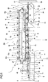
- the assembling and feeding device 1 comprises at least one first conveyor 7 which is movable, for at least one stretch of it, along a first feed path P1 of the first component 3 from a first pick-up station 8 to a release station 9.
- the device 1 also comprises a second conveyor 10 moving for at least one stretch of it along a second feed path P2 of the second component 4 from a second pick-up station 11 to at least one reciprocal coupling and assembly station 12.
- the first and second feed paths P1, P2 have, starting from an area close to the first and the second pick-up stations 8 and 11, at least a first stretch T1 in which they converge towards the reciprocal coupling and assembly station 12 at which the finished article 2 is defined.
- the first stretch T1 extends from a zone between the first and the second pick-up stations 8 and 11.
- the zone from which the stretch T1 extends is located at the second pick-up station 11.
- first and the second paths P1 and P2 are substantially rectilinear along the first stretch T1.
- the first and second feed paths P1 and P2 have at least a second stretch T2, starting from the coupling and assembly station 12, in which they are substantially parallel and along which one of the two conveyors 7 and 10 feeds the finished article 2 forward towards the release station 9.
- the first conveyor 7 comprises a support surface 13 forming the first feed path P1 and along which the first component 3 moves along the first stretch T1 of the first and second feed paths P1 and P2 and the finished article 2 moves along the second stretch T2.
- the first conveyor 7 comprises a first movement means 14 and a second movement means 15.
- the first movement means 14 feed the first components 3 forward along the respective first feed path P1 from the first pick-up station 8 towards the reciprocal coupling and assembly station 12, whilst the second movement means 15 feed the finished articles 2 forward along the respective first feed path P1, downstream of he reciprocal coupling and assembly station 12 to the release station 9.
- the first movement means 14 feed the first components 3 forward along the first feed path P1 of the first pick-up station 8 to a station 11a, intermediate between the second pick-up station 11 and the reciprocal assembly station 12 between the first and the second components 3 and 4.
- the station 11a is an intermediate station, at which the first component 3 is transferred from the first movement means 14 to the second conveyor 10.
- the first movement means 14, positioned close to the first pick-up station 8, is fitted with a first chain 16 and first pushing means 17 distributed uniformly along it according to a predetermined spacing.
- the first chain 16 is looped around a drive pulley 18, rotatable about its axis 18a, and around a driven pulley, not illustrated.
- the first pushing means 17 are hinged in the known manner to the first chain 16 and comprise a first projection 19 protruding by a predetermined length above the support surface 13 for moving forward the base components 3.
- the second movement means 15 is positioned downstream of the coupling station 12 and comprises, similarly to the first movement means 14, second pushing means 20 distributed according to a predetermined spacing along a second chain 21.
- the second chain 21 is looped around a driven pulley 22 and a drive pulley 23 rotatable about respective axes 22a and 23a.
- the second pushing means 20, hinged in the known manner to the second chain 21, comprise a second projection 24 protruding by a predetermined length above the support surface 13 for moving forward the finished articles 2.
- the second conveyor 10 transfers the first and second components 3 and 4 from the first to the second movement means 14 and 15 along the intermediate stretch T3 of the support surface 13.
- the second conveyor 10 moves along the first feed path P1 of the first component 3 from the second pick-up station 11 to the release station 9 and feeds the finished article 2 forward along the second stretch T2 of the first and second feed paths P1 and P2.
- the second conveyor 10 comprises a drive pulley 59 and a driven pulley 60 rotatable about respective axes 59a and 60a.
- the second conveyor 10 also comprises a plurality of suction means 25 distributed equidistantly along its periphery.
- the suction means 25 are designed to hold the second components 4 from the second pick-up station 11 to the reciprocal coupling and assembly station 12, along the second feed path P2.
- the suction means 25 consist of a cylindrical shaped aspirator 26 with axis 26a, each fitted with a through duct 27, coaxial with the axis 26a.
- the duct 27 has a suction inlet 28 designed to hold the accessory component 4.
- the second conveyor 10 comprises a belt 29, wound around the pulleys 59 and 60.
- the belt 29 is fitted with a plurality of equally spaced holes 30.
- the aspirators 26 are fixed to the belt 29 in such a way that each duct 27 is coaxial with the hole 30 of the belt 29.
- the aspirators 26 extend outside the belt 29 and their free end 31 is fitted with the suction inlet 28.
- the free end 31 and the belt 29 are positioned at a reciprocal distance d1.
- the end 31 is concave so as to couple with the upper surface 4b of the accessory component 4.
- a chamber 32 connected to means for forming the vacuum not illustrated, is defined by a plurality of fixed walls 33, whilst the conveyor belt 29 defines the lower wall 34.
- the chamber 32 extends substantially from the second pick-up station 11 to the reciprocal coupling and assembly station 12.
- the aspirators 26 are in fluid communication with the chamber 32 and hold the accessory component 4 by suction.
- the aspirators 26 since they are not in fluid communication with the chamber 32, release the accessory component 4 inside the cavity 5 of the base component 3.
- the second conveyor 10 also comprises a plurality of pushing means 35 feeding the first component 3 forward along the support surface 13.
- Each pushing means 35 is associated with a suction means 25 forming in this way an alignment device 36.
- each alignment device 36 is positioned, along the second feed path P2, at a defined distance d from the suction means 25, the distance d defining the alignment distance of the second component 4 from the first component 3, in such a way that the second component 4 correctly enters the cavity 5 of the first component 3.
- a supporting element 37 makes the aspirator 26 integral with the respective pushing means 35.
- the supporting element 37 keeps the distance d fixed guaranteeing over time a correct alignment between the cavity 5 of the base component 3 and the accessory component 4 to be inserted inside it.
- the pushing means 35 comprise a rod 38 fitted, at its upper end, with a cam follower roller 39, and, at its lower end, with a feed bar 40.
- the feed bar 40 rests along the rear side wall 41, relative to the feed direction, of the first component 3 moving it forward along the support surface 13, as illustrated in Figure 4 .
- the distance is therefore defined along the second path P2 from the axis 26a of the aspirator 26 to the side wall 40a of the bar 40 resting along the side wall 41 of the first component 3.
- the supporting element 37 is fitted with a through hole 42 inside which the rod 38 of the pushing means 35 is free to move vertically.
- the rollers 39 of the pushing means 35 engage in a grooved guide 43 made in a support plate 44.
- the plate 44 extends along a longitudinal axis B parallel to the second conveyor 10.
- the grooved guide 43 forms a movement path C of the pushing means 35 and moves the rod 38 vertically.
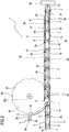
- the path C is characterised by three operational stretches, indicated in Figures 1 and 3 with C1, C2 and C3, and a non-operational stretch C4.
- the stretches C1, C2 and C3 are defined as operational since, along them, the pushing means 35 face the support surface 13.
- the stretch C2, between the stretches C1 and C3, is substantially parallel to the longitudinal axis B, consequently, the distance between the rollers 39 engaged in the guide 43 and the longitudinal axis B is substantially constant.
- the operational stretch C3 is substantially parallel to the longitudinal axis B and keeps the distance between the rollers 39 engaged in the guide 43 and the longitudinal axis B constant, similarly to the operational stretch C2. Moreover, unlike the embodiment illustrated in Figure 1 , the above-mentioned second movement means 15 is not fitted in this alternative embodiment.
- the non-operational stretch C4 is formed by joining the final portion of the stretch C3 with the initial portion of the stretch C1.
- a station 45 for applying the layer of adhesive substance 6 is located downstream of the first pick-up station 8.
- the station 45 comprises a nozzle 46 connected to a tank 47 containing the adhesive substance.
- a pump 48 draws the adhesive substance from the tank 47 and feeds the nozzle 46.
- a sensor 49 for detecting the presence of the base component 3 activates the pump 48 when the cavity 5 of the base component 3 is aligned with the nozzle 46.
- the pump 48 feeds the nozzle 46 periodically according to the movement interval of the base components 3.
- a distributor disc 50 is located upstream of the second pick-up station 11 and downstream of a feed station 51.
- the distributor disc 50 which rotates relative to its vertical axis 50a, is fitted with a plurality of pockets 52 located along its outer periphery and spaced at predetermined equal intervals.
- the pockets 52 comprise a recess 53 shaped so as to couple with the outer surface of the accessory component 4.
- a side panel 54 faces the outer periphery of the disc 50.
- a feeder 55 fitted with two guides 56, moves forward the accessory components 4 aligned with each other.
- the first protrusions 19 of the first pushing means 17 pick up the base components 3 from the first pick-up station 8 and move them forward along the support surface 13 spaced apart from each other by a predetermined interval.
- the base components 3 then cross the station 45 which deposits the layer of adhesive substance 6 inside the cavity 5 of the first components 3.
- the pockets 52 of the rotary disc 50 pick up in succession the accessory components 4 from the feed station 51 and carry them continuously to the second pick-up station 11 of the second conveyor 10.
- the side panel 54 acts in conjunction with the disc 50 so as to hold the accessory components 4 during their transport.
- the aspirator 26 connected to the vacuum chamber 32, picks up in succession the accessory components 4 carried by the disc 50.
- the roller 39 of the pushing means 35 associated with the aspirator 26 holding the accessory component 4 moves along the operational stretch C1 of the grooved guide 43.
- the rod 39 and, consequently, the bar 40 move in progression towards the support surface 13 along which the base components 3 are carried by the first pushing means 17.
- the pushing means 35 of the second conveyor 10 are synchronised with the first pushing means 17 and each feeds the first component 3 along the first stretch T1 of the first and second feed paths P1 and P2.
- the rod 39 is lowered in such a way that the bar 40 takes the base component 3 from the first projection 19 of the first pushing means 17 which abandons it progressively.
- the base component 3 is then carried by the pushing means 35 to the reciprocal coupling and assembly station 12, whilst the roller 39 moves along the stretch C2 of the grooved guide 43.
- the aspirator 26 releases the accessory component 4 which inserts partly inside the cavity 5 of the base component 3.
- the pushing means 35 are synchronised with the second pushing means 20 and each feeds the finished articles 2 towards the release station 9.
- the rod 38 of the roller 39 which moves along the operational stretch C3 moves away from the support surface 13 in such a way that the bar 40 disengages the side panel 41 of the base component 3 and the second protrusion 24 takes the finished article 2 from the pushing means 35.
- the roller 39 After completing stretch C3, the roller 39 starts to move along the non-operational stretch C4, until, following the rotation of the second conveyor 10, it starts again to engage in the operational stretch C1 of the grooved guide 43. Downstream of the release station 9, an inspection station 57 checks the quality of the finished article 2.
- Images are analysed to check that the conformity criteria of the article 2 defined by the production company are complied with. For example, it is assessed whether the accessory component 4 is present inside the cavity 5 of the base component 3 and whether the base component 3 and the accessory component 4 are damaged.
- a packaging machine 58 Downstream of the inspection station 57 a packaging machine 58, shown schematically, packages the articles 2.
- the device 1 is relatively simple from a constructional and structural point of view, indeed, unlike the prior art, the suction means 25 are fixed relative to the second conveyor 10 and feed the second components 4, whilst the first components 3 move along the support surface 13 forming the stretch T1, along which the first components 3 move towards the second components 4 until joining and forming the finished article 2. Moreover, since the first components 3 are gently accompanied along the support surface 13, denting or damaging of the first components 3 is avoided, considerably reducing the rejects of the finished articles 2.
- the alignment between the cavity 5 of the first component 3 and the second component 4 is guaranteed by a single device 36, unlike prior art devices. Indeed, since the pushing means 35 is integral with the aspirator 26, it is ensured that the alignment distance d between the accessory component 4 and the base component 3 is maintained fixed over time.
Landscapes
- Engineering & Computer Science (AREA)
- Mechanical Engineering (AREA)
- Specific Conveyance Elements (AREA)
- Structure Of Belt Conveyors (AREA)
Applications Claiming Priority (1)
| Application Number | Priority Date | Filing Date | Title |
|---|---|---|---|
| IT000177A ITBO20110177A1 (it) | 2011-04-06 | 2011-04-06 | Dispositivo di assemblaggio e di alimentazione di articoli di piccole dimensioni ad una macchina impacchettatrice. |
Publications (2)
| Publication Number | Publication Date |
|---|---|
| EP2508433A1 true EP2508433A1 (de) | 2012-10-10 |
| EP2508433B1 EP2508433B1 (de) | 2016-05-11 |
Family
ID=44120380
Family Applications (1)
| Application Number | Title | Priority Date | Filing Date |
|---|---|---|---|
| EP12162035.5A Active EP2508433B1 (de) | 2011-04-06 | 2012-03-29 | Vorrichtung zum Zusammensetzen und Zuführen von kleinen Artikeln in eine Verpackungsmaschine |
Country Status (3)
| Country | Link |
|---|---|
| EP (1) | EP2508433B1 (de) |
| IT (1) | ITBO20110177A1 (de) |
| PL (1) | PL2508433T3 (de) |
Cited By (2)
| Publication number | Priority date | Publication date | Assignee | Title |
|---|---|---|---|---|
| JP2017140689A (ja) * | 2016-02-13 | 2017-08-17 | 青山 省司 | 部品取り出し位置決め装置 |
| CN114406637A (zh) * | 2022-01-26 | 2022-04-29 | 宁波市鄞州永佳电机工具有限公司 | 一种气动插批头工装 |
Citations (5)
| Publication number | Priority date | Publication date | Assignee | Title |
|---|---|---|---|---|
| US4470194A (en) * | 1981-09-14 | 1984-09-11 | Omega Officine Meccaniche S.P.A. | Device for slipping washers and like onto shanks of screws and the like |
| EP1048569A2 (de) | 1999-04-23 | 2000-11-02 | SIG Pack Systems AG | Vorrichtung zum Zuführen von aus zwei Komponenten bestehenden Stückgütern in eine Verpackungsmaschine |
| EP1270455A1 (de) | 2001-06-25 | 2003-01-02 | THEEGARTEN-PACTEC GMBH & CO. KG | Verfahren und Vorrichtung zur Montage und Verpackung kleinstueckiger Artikel |
| US20030135978A1 (en) * | 2002-01-23 | 2003-07-24 | Safety Syringes, Inc. | Systems and methods for assembling injection device |
| DE202006019187U1 (de) | 2006-12-20 | 2007-02-22 | Robert Bosch Gmbh | Vorrichtung zur Montage kleinstückiger Artikel |
-
2011
- 2011-04-06 IT IT000177A patent/ITBO20110177A1/it unknown
-
2012
- 2012-03-29 PL PL12162035.5T patent/PL2508433T3/pl unknown
- 2012-03-29 EP EP12162035.5A patent/EP2508433B1/de active Active
Patent Citations (5)
| Publication number | Priority date | Publication date | Assignee | Title |
|---|---|---|---|---|
| US4470194A (en) * | 1981-09-14 | 1984-09-11 | Omega Officine Meccaniche S.P.A. | Device for slipping washers and like onto shanks of screws and the like |
| EP1048569A2 (de) | 1999-04-23 | 2000-11-02 | SIG Pack Systems AG | Vorrichtung zum Zuführen von aus zwei Komponenten bestehenden Stückgütern in eine Verpackungsmaschine |
| EP1270455A1 (de) | 2001-06-25 | 2003-01-02 | THEEGARTEN-PACTEC GMBH & CO. KG | Verfahren und Vorrichtung zur Montage und Verpackung kleinstueckiger Artikel |
| US20030135978A1 (en) * | 2002-01-23 | 2003-07-24 | Safety Syringes, Inc. | Systems and methods for assembling injection device |
| DE202006019187U1 (de) | 2006-12-20 | 2007-02-22 | Robert Bosch Gmbh | Vorrichtung zur Montage kleinstückiger Artikel |
Cited By (3)
| Publication number | Priority date | Publication date | Assignee | Title |
|---|---|---|---|---|
| JP2017140689A (ja) * | 2016-02-13 | 2017-08-17 | 青山 省司 | 部品取り出し位置決め装置 |
| CN114406637A (zh) * | 2022-01-26 | 2022-04-29 | 宁波市鄞州永佳电机工具有限公司 | 一种气动插批头工装 |
| CN114406637B (zh) * | 2022-01-26 | 2023-11-14 | 宁波市鄞州永佳电机工具有限公司 | 一种气动插批头工装 |
Also Published As
| Publication number | Publication date |
|---|---|
| EP2508433B1 (de) | 2016-05-11 |
| PL2508433T3 (pl) | 2016-10-31 |
| ITBO20110177A1 (it) | 2012-10-07 |
Similar Documents
| Publication | Publication Date | Title |
|---|---|---|
| US20100242412A1 (en) | Method and device for producing cigarette packs | |
| US20110048893A1 (en) | Conveying apparatus | |
| JP2000501679A (ja) | 包装装置 | |
| CN109850249B (zh) | 用于运输包装的设备 | |
| JP2007522043A (ja) | 貯留容器からシートのカップ部へと製品を移送するための方法及び装置 | |
| EP1640274A2 (de) | Verfahren und Vorrichtung zum Aufbringen eines Etiketts auf einen Gegenstand | |
| CN100534769C (zh) | 软管管筒的传送转移装置 | |
| ITBO20120170A1 (it) | Macchina e procedimento per la formazione di capsule monouso per bevande | |
| US4592374A (en) | Process and apparatus for forming groups of cigarettes | |
| US20120027562A1 (en) | Machine system and method for transferring and grouping articles and packaging machine | |
| US5641053A (en) | Equally spaced product conveying method and line | |
| CN108472910B (zh) | 装盒机的操作组,装盒机以及形成纸盒的方法 | |
| EP2508433B1 (de) | Vorrichtung zum Zusammensetzen und Zuführen von kleinen Artikeln in eine Verpackungsmaschine | |
| JP6613228B2 (ja) | ロッド状の物品を運搬するためのシステムおよび方法、ならびにロッド状の物品をコンベヤーバンド内に保持するための配列および方法 | |
| US5409098A (en) | Apparatus for the transport of cigarette packs | |
| JP2011522759A (ja) | 製品搬送ユニット | |
| JPH11510773A (ja) | カートン給送開口ホイールアセンブリ | |
| US20160075459A1 (en) | Method and device for handling elongated articles | |
| EP1352835A2 (de) | Vorrichtung zum Übertragen von Gegenständen und eine mit dieser Vorrichtung versehene Einwickelmaschine | |
| JP6475144B2 (ja) | 箱詰め装置 | |
| KR101733282B1 (ko) | 로터리형 자동포장기 | |
| US4819343A (en) | Apparatus for the storage of (cigarette) packs | |
| KR200296666Y1 (ko) | 수직형 파우치 포장기 | |
| KR20170079386A (ko) | 제품 이송장치 | |
| JP6462556B2 (ja) | 箱詰め装置 |
Legal Events
| Date | Code | Title | Description |
|---|---|---|---|
| PUAI | Public reference made under article 153(3) epc to a published international application that has entered the european phase |
Free format text: ORIGINAL CODE: 0009012 |
|
| AK | Designated contracting states |
Kind code of ref document: A1 Designated state(s): AL AT BE BG CH CY CZ DE DK EE ES FI FR GB GR HR HU IE IS IT LI LT LU LV MC MK MT NL NO PL PT RO RS SE SI SK SM TR |
|
| AX | Request for extension of the european patent |
Extension state: BA ME |
|
| 17P | Request for examination filed |
Effective date: 20130409 |
|
| RIC1 | Information provided on ipc code assigned before grant |
Ipc: B23P 19/04 20060101ALI20130729BHEP Ipc: B23P 19/00 20060101ALI20130729BHEP Ipc: B65B 35/54 20060101AFI20130729BHEP |
|
| 17Q | First examination report despatched |
Effective date: 20140423 |
|
| GRAP | Despatch of communication of intention to grant a patent |
Free format text: ORIGINAL CODE: EPIDOSNIGR1 |
|
| INTG | Intention to grant announced |
Effective date: 20151110 |
|
| GRAS | Grant fee paid |
Free format text: ORIGINAL CODE: EPIDOSNIGR3 |
|
| GRAA | (expected) grant |
Free format text: ORIGINAL CODE: 0009210 |
|
| AK | Designated contracting states |
Kind code of ref document: B1 Designated state(s): AL AT BE BG CH CY CZ DE DK EE ES FI FR GB GR HR HU IE IS IT LI LT LU LV MC MK MT NL NO PL PT RO RS SE SI SK SM TR |
|
| REG | Reference to a national code |
Ref country code: GB Ref legal event code: FG4D |
|
| REG | Reference to a national code |
Ref country code: CH Ref legal event code: EP |
|
| REG | Reference to a national code |
Ref country code: AT Ref legal event code: REF Ref document number: 798449 Country of ref document: AT Kind code of ref document: T Effective date: 20160515 |
|
| REG | Reference to a national code |
Ref country code: IE Ref legal event code: FG4D |
|
| REG | Reference to a national code |
Ref country code: DE Ref legal event code: R096 Ref document number: 602012018265 Country of ref document: DE |
|
| REG | Reference to a national code |
Ref country code: LT Ref legal event code: MG4D |
|
| REG | Reference to a national code |
Ref country code: NL Ref legal event code: MP Effective date: 20160511 |
|
| PG25 | Lapsed in a contracting state [announced via postgrant information from national office to epo] |
Ref country code: FI Free format text: LAPSE BECAUSE OF FAILURE TO SUBMIT A TRANSLATION OF THE DESCRIPTION OR TO PAY THE FEE WITHIN THE PRESCRIBED TIME-LIMIT Effective date: 20160511 Ref country code: NO Free format text: LAPSE BECAUSE OF FAILURE TO SUBMIT A TRANSLATION OF THE DESCRIPTION OR TO PAY THE FEE WITHIN THE PRESCRIBED TIME-LIMIT Effective date: 20160811 Ref country code: NL Free format text: LAPSE BECAUSE OF FAILURE TO SUBMIT A TRANSLATION OF THE DESCRIPTION OR TO PAY THE FEE WITHIN THE PRESCRIBED TIME-LIMIT Effective date: 20160511 Ref country code: LT Free format text: LAPSE BECAUSE OF FAILURE TO SUBMIT A TRANSLATION OF THE DESCRIPTION OR TO PAY THE FEE WITHIN THE PRESCRIBED TIME-LIMIT Effective date: 20160511 |
|
| REG | Reference to a national code |
Ref country code: AT Ref legal event code: MK05 Ref document number: 798449 Country of ref document: AT Kind code of ref document: T Effective date: 20160511 |
|
| PG25 | Lapsed in a contracting state [announced via postgrant information from national office to epo] |
Ref country code: SE Free format text: LAPSE BECAUSE OF FAILURE TO SUBMIT A TRANSLATION OF THE DESCRIPTION OR TO PAY THE FEE WITHIN THE PRESCRIBED TIME-LIMIT Effective date: 20160511 Ref country code: HR Free format text: LAPSE BECAUSE OF FAILURE TO SUBMIT A TRANSLATION OF THE DESCRIPTION OR TO PAY THE FEE WITHIN THE PRESCRIBED TIME-LIMIT Effective date: 20160511 Ref country code: RS Free format text: LAPSE BECAUSE OF FAILURE TO SUBMIT A TRANSLATION OF THE DESCRIPTION OR TO PAY THE FEE WITHIN THE PRESCRIBED TIME-LIMIT Effective date: 20160511 Ref country code: GR Free format text: LAPSE BECAUSE OF FAILURE TO SUBMIT A TRANSLATION OF THE DESCRIPTION OR TO PAY THE FEE WITHIN THE PRESCRIBED TIME-LIMIT Effective date: 20160812 Ref country code: LV Free format text: LAPSE BECAUSE OF FAILURE TO SUBMIT A TRANSLATION OF THE DESCRIPTION OR TO PAY THE FEE WITHIN THE PRESCRIBED TIME-LIMIT Effective date: 20160511 Ref country code: ES Free format text: LAPSE BECAUSE OF FAILURE TO SUBMIT A TRANSLATION OF THE DESCRIPTION OR TO PAY THE FEE WITHIN THE PRESCRIBED TIME-LIMIT Effective date: 20160511 Ref country code: PT Free format text: LAPSE BECAUSE OF FAILURE TO SUBMIT A TRANSLATION OF THE DESCRIPTION OR TO PAY THE FEE WITHIN THE PRESCRIBED TIME-LIMIT Effective date: 20160912 |
|
| PG25 | Lapsed in a contracting state [announced via postgrant information from national office to epo] |
Ref country code: RO Free format text: LAPSE BECAUSE OF FAILURE TO SUBMIT A TRANSLATION OF THE DESCRIPTION OR TO PAY THE FEE WITHIN THE PRESCRIBED TIME-LIMIT Effective date: 20160511 Ref country code: EE Free format text: LAPSE BECAUSE OF FAILURE TO SUBMIT A TRANSLATION OF THE DESCRIPTION OR TO PAY THE FEE WITHIN THE PRESCRIBED TIME-LIMIT Effective date: 20160511 Ref country code: DK Free format text: LAPSE BECAUSE OF FAILURE TO SUBMIT A TRANSLATION OF THE DESCRIPTION OR TO PAY THE FEE WITHIN THE PRESCRIBED TIME-LIMIT Effective date: 20160511 Ref country code: SK Free format text: LAPSE BECAUSE OF FAILURE TO SUBMIT A TRANSLATION OF THE DESCRIPTION OR TO PAY THE FEE WITHIN THE PRESCRIBED TIME-LIMIT Effective date: 20160511 Ref country code: CZ Free format text: LAPSE BECAUSE OF FAILURE TO SUBMIT A TRANSLATION OF THE DESCRIPTION OR TO PAY THE FEE WITHIN THE PRESCRIBED TIME-LIMIT Effective date: 20160511 |
|
| REG | Reference to a national code |
Ref country code: DE Ref legal event code: R097 Ref document number: 602012018265 Country of ref document: DE |
|
| PG25 | Lapsed in a contracting state [announced via postgrant information from national office to epo] |
Ref country code: BE Free format text: LAPSE BECAUSE OF FAILURE TO SUBMIT A TRANSLATION OF THE DESCRIPTION OR TO PAY THE FEE WITHIN THE PRESCRIBED TIME-LIMIT Effective date: 20160511 Ref country code: AT Free format text: LAPSE BECAUSE OF FAILURE TO SUBMIT A TRANSLATION OF THE DESCRIPTION OR TO PAY THE FEE WITHIN THE PRESCRIBED TIME-LIMIT Effective date: 20160511 Ref country code: SM Free format text: LAPSE BECAUSE OF FAILURE TO SUBMIT A TRANSLATION OF THE DESCRIPTION OR TO PAY THE FEE WITHIN THE PRESCRIBED TIME-LIMIT Effective date: 20160511 |
|
| PLBE | No opposition filed within time limit |
Free format text: ORIGINAL CODE: 0009261 |
|
| STAA | Information on the status of an ep patent application or granted ep patent |
Free format text: STATUS: NO OPPOSITION FILED WITHIN TIME LIMIT |
|
| 26N | No opposition filed |
Effective date: 20170214 |
|
| PG25 | Lapsed in a contracting state [announced via postgrant information from national office to epo] |
Ref country code: SI Free format text: LAPSE BECAUSE OF FAILURE TO SUBMIT A TRANSLATION OF THE DESCRIPTION OR TO PAY THE FEE WITHIN THE PRESCRIBED TIME-LIMIT Effective date: 20160511 |
|
| REG | Reference to a national code |
Ref country code: DE Ref legal event code: R119 Ref document number: 602012018265 Country of ref document: DE |
|
| REG | Reference to a national code |
Ref country code: CH Ref legal event code: PL |
|
| GBPC | Gb: european patent ceased through non-payment of renewal fee |
Effective date: 20170329 |
|
| PG25 | Lapsed in a contracting state [announced via postgrant information from national office to epo] |
Ref country code: MC Free format text: LAPSE BECAUSE OF FAILURE TO SUBMIT A TRANSLATION OF THE DESCRIPTION OR TO PAY THE FEE WITHIN THE PRESCRIBED TIME-LIMIT Effective date: 20160511 |
|
| REG | Reference to a national code |
Ref country code: IE Ref legal event code: MM4A |
|
| REG | Reference to a national code |
Ref country code: FR Ref legal event code: ST Effective date: 20171130 |
|
| PG25 | Lapsed in a contracting state [announced via postgrant information from national office to epo] |
Ref country code: FR Free format text: LAPSE BECAUSE OF NON-PAYMENT OF DUE FEES Effective date: 20170331 Ref country code: LU Free format text: LAPSE BECAUSE OF NON-PAYMENT OF DUE FEES Effective date: 20170329 Ref country code: DE Free format text: LAPSE BECAUSE OF NON-PAYMENT OF DUE FEES Effective date: 20171003 |
|
| PG25 | Lapsed in a contracting state [announced via postgrant information from national office to epo] |
Ref country code: IE Free format text: LAPSE BECAUSE OF NON-PAYMENT OF DUE FEES Effective date: 20170329 Ref country code: CH Free format text: LAPSE BECAUSE OF NON-PAYMENT OF DUE FEES Effective date: 20170331 Ref country code: IT Free format text: LAPSE BECAUSE OF NON-PAYMENT OF DUE FEES Effective date: 20170329 Ref country code: LI Free format text: LAPSE BECAUSE OF NON-PAYMENT OF DUE FEES Effective date: 20170331 Ref country code: GB Free format text: LAPSE BECAUSE OF NON-PAYMENT OF DUE FEES Effective date: 20170329 |
|
| PG25 | Lapsed in a contracting state [announced via postgrant information from national office to epo] |
Ref country code: MT Free format text: LAPSE BECAUSE OF NON-PAYMENT OF DUE FEES Effective date: 20170329 |
|
| PG25 | Lapsed in a contracting state [announced via postgrant information from national office to epo] |
Ref country code: PL Free format text: LAPSE BECAUSE OF NON-PAYMENT OF DUE FEES Effective date: 20170329 Ref country code: AL Free format text: LAPSE BECAUSE OF FAILURE TO SUBMIT A TRANSLATION OF THE DESCRIPTION OR TO PAY THE FEE WITHIN THE PRESCRIBED TIME-LIMIT Effective date: 20160511 |
|
| PG25 | Lapsed in a contracting state [announced via postgrant information from national office to epo] |
Ref country code: HU Free format text: LAPSE BECAUSE OF FAILURE TO SUBMIT A TRANSLATION OF THE DESCRIPTION OR TO PAY THE FEE WITHIN THE PRESCRIBED TIME-LIMIT; INVALID AB INITIO Effective date: 20120329 |
|
| PG25 | Lapsed in a contracting state [announced via postgrant information from national office to epo] |
Ref country code: BG Free format text: LAPSE BECAUSE OF FAILURE TO SUBMIT A TRANSLATION OF THE DESCRIPTION OR TO PAY THE FEE WITHIN THE PRESCRIBED TIME-LIMIT Effective date: 20160511 |
|
| PG25 | Lapsed in a contracting state [announced via postgrant information from national office to epo] |
Ref country code: CY Free format text: LAPSE BECAUSE OF NON-PAYMENT OF DUE FEES Effective date: 20160511 |
|
| PG25 | Lapsed in a contracting state [announced via postgrant information from national office to epo] |
Ref country code: MK Free format text: LAPSE BECAUSE OF FAILURE TO SUBMIT A TRANSLATION OF THE DESCRIPTION OR TO PAY THE FEE WITHIN THE PRESCRIBED TIME-LIMIT Effective date: 20160511 |
|
| PG25 | Lapsed in a contracting state [announced via postgrant information from national office to epo] |
Ref country code: IS Free format text: LAPSE BECAUSE OF FAILURE TO SUBMIT A TRANSLATION OF THE DESCRIPTION OR TO PAY THE FEE WITHIN THE PRESCRIBED TIME-LIMIT Effective date: 20160911 |