EP1265792B1 - Behälter mit drehverschluss - Google Patents
Behälter mit drehverschluss Download PDFInfo
- Publication number
- EP1265792B1 EP1265792B1 EP01915312A EP01915312A EP1265792B1 EP 1265792 B1 EP1265792 B1 EP 1265792B1 EP 01915312 A EP01915312 A EP 01915312A EP 01915312 A EP01915312 A EP 01915312A EP 1265792 B1 EP1265792 B1 EP 1265792B1
- Authority
- EP
- European Patent Office
- Prior art keywords
- wall
- lid
- opening
- container
- drinking
- Prior art date
- Legal status (The legal status is an assumption and is not a legal conclusion. Google has not performed a legal analysis and makes no representation as to the accuracy of the status listed.)
- Expired - Lifetime
Links
Images




Classifications
-
- B—PERFORMING OPERATIONS; TRANSPORTING
- B65—CONVEYING; PACKING; STORING; HANDLING THIN OR FILAMENTARY MATERIAL
- B65D—CONTAINERS FOR STORAGE OR TRANSPORT OF ARTICLES OR MATERIALS, e.g. BAGS, BARRELS, BOTTLES, BOXES, CANS, CARTONS, CRATES, DRUMS, JARS, TANKS, HOPPERS, FORWARDING CONTAINERS; ACCESSORIES, CLOSURES, OR FITTINGS THEREFOR; PACKAGING ELEMENTS; PACKAGES
- B65D51/00—Closures not otherwise provided for
- B65D51/18—Arrangements of closures with protective outer cap-like covers or of two or more co-operating closures
- B65D51/20—Caps, lids, or covers co-operating with an inner closure arranged to be opened by piercing, cutting, or tearing
- B65D51/22—Caps, lids, or covers co-operating with an inner closure arranged to be opened by piercing, cutting, or tearing having means for piercing, cutting, or tearing the inner closure
-
- B—PERFORMING OPERATIONS; TRANSPORTING
- B65—CONVEYING; PACKING; STORING; HANDLING THIN OR FILAMENTARY MATERIAL
- B65D—CONTAINERS FOR STORAGE OR TRANSPORT OF ARTICLES OR MATERIALS, e.g. BAGS, BARRELS, BOTTLES, BOXES, CANS, CARTONS, CRATES, DRUMS, JARS, TANKS, HOPPERS, FORWARDING CONTAINERS; ACCESSORIES, CLOSURES, OR FITTINGS THEREFOR; PACKAGING ELEMENTS; PACKAGES
- B65D51/00—Closures not otherwise provided for
- B65D51/18—Arrangements of closures with protective outer cap-like covers or of two or more co-operating closures
- B65D51/20—Caps, lids, or covers co-operating with an inner closure arranged to be opened by piercing, cutting, or tearing
- B65D51/22—Caps, lids, or covers co-operating with an inner closure arranged to be opened by piercing, cutting, or tearing having means for piercing, cutting, or tearing the inner closure
- B65D51/221—Caps, lids, or covers co-operating with an inner closure arranged to be opened by piercing, cutting, or tearing having means for piercing, cutting, or tearing the inner closure a major part of the inner closure being left inside the container after the opening
- B65D51/222—Caps, lids, or covers co-operating with an inner closure arranged to be opened by piercing, cutting, or tearing having means for piercing, cutting, or tearing the inner closure a major part of the inner closure being left inside the container after the opening the piercing or cutting means being integral with, or fixedly attached to, the outer closure
-
- B—PERFORMING OPERATIONS; TRANSPORTING
- B65—CONVEYING; PACKING; STORING; HANDLING THIN OR FILAMENTARY MATERIAL
- B65D—CONTAINERS FOR STORAGE OR TRANSPORT OF ARTICLES OR MATERIALS, e.g. BAGS, BARRELS, BOTTLES, BOXES, CANS, CARTONS, CRATES, DRUMS, JARS, TANKS, HOPPERS, FORWARDING CONTAINERS; ACCESSORIES, CLOSURES, OR FITTINGS THEREFOR; PACKAGING ELEMENTS; PACKAGES
- B65D17/00—Rigid or semi-rigid containers specially constructed to be opened by cutting or piercing, or by tearing of frangible members or portions
- B65D17/52—Attachment of opening tools, e.g. slotted keys, to containers
- B65D17/521—Attached can-cutting devices
-
- B—PERFORMING OPERATIONS; TRANSPORTING
- B65—CONVEYING; PACKING; STORING; HANDLING THIN OR FILAMENTARY MATERIAL
- B65D—CONTAINERS FOR STORAGE OR TRANSPORT OF ARTICLES OR MATERIALS, e.g. BAGS, BARRELS, BOTTLES, BOXES, CANS, CARTONS, CRATES, DRUMS, JARS, TANKS, HOPPERS, FORWARDING CONTAINERS; ACCESSORIES, CLOSURES, OR FITTINGS THEREFOR; PACKAGING ELEMENTS; PACKAGES
- B65D47/00—Closures with filling and discharging, or with discharging, devices
- B65D47/04—Closures with discharging devices other than pumps
- B65D47/20—Closures with discharging devices other than pumps comprising hand-operated members for controlling discharge
- B65D47/26—Closures with discharging devices other than pumps comprising hand-operated members for controlling discharge with slide valves, i.e. valves that open and close a passageway by sliding over a port, e.g. formed with slidable spouts
- B65D47/261—Closures with discharging devices other than pumps comprising hand-operated members for controlling discharge with slide valves, i.e. valves that open and close a passageway by sliding over a port, e.g. formed with slidable spouts having a rotational or helicoidal movement
- B65D47/265—Closures with discharging devices other than pumps comprising hand-operated members for controlling discharge with slide valves, i.e. valves that open and close a passageway by sliding over a port, e.g. formed with slidable spouts having a rotational or helicoidal movement between planar parts
-
- B—PERFORMING OPERATIONS; TRANSPORTING
- B65—CONVEYING; PACKING; STORING; HANDLING THIN OR FILAMENTARY MATERIAL
- B65D—CONTAINERS FOR STORAGE OR TRANSPORT OF ARTICLES OR MATERIALS, e.g. BAGS, BARRELS, BOTTLES, BOXES, CANS, CARTONS, CRATES, DRUMS, JARS, TANKS, HOPPERS, FORWARDING CONTAINERS; ACCESSORIES, CLOSURES, OR FITTINGS THEREFOR; PACKAGING ELEMENTS; PACKAGES
- B65D51/00—Closures not otherwise provided for
- B65D51/24—Closures not otherwise provided for combined or co-operating with auxiliary devices for non-closing purposes
- B65D51/248—Closures not otherwise provided for combined or co-operating with auxiliary devices for non-closing purposes the closure being provided with transient audible or visual signaling means, e.g. for indicating dispensing, or other illuminating or acoustic devices, e.g. whistles
-
- B—PERFORMING OPERATIONS; TRANSPORTING
- B65—CONVEYING; PACKING; STORING; HANDLING THIN OR FILAMENTARY MATERIAL
- B65D—CONTAINERS FOR STORAGE OR TRANSPORT OF ARTICLES OR MATERIALS, e.g. BAGS, BARRELS, BOTTLES, BOXES, CANS, CARTONS, CRATES, DRUMS, JARS, TANKS, HOPPERS, FORWARDING CONTAINERS; ACCESSORIES, CLOSURES, OR FITTINGS THEREFOR; PACKAGING ELEMENTS; PACKAGES
- B65D2251/00—Details relating to container closures
- B65D2251/0003—Two or more closures
- B65D2251/0006—Upper closure
- B65D2251/0025—Upper closure of the 47-type
-
- B—PERFORMING OPERATIONS; TRANSPORTING
- B65—CONVEYING; PACKING; STORING; HANDLING THIN OR FILAMENTARY MATERIAL
- B65D—CONTAINERS FOR STORAGE OR TRANSPORT OF ARTICLES OR MATERIALS, e.g. BAGS, BARRELS, BOTTLES, BOXES, CANS, CARTONS, CRATES, DRUMS, JARS, TANKS, HOPPERS, FORWARDING CONTAINERS; ACCESSORIES, CLOSURES, OR FITTINGS THEREFOR; PACKAGING ELEMENTS; PACKAGES
- B65D2251/00—Details relating to container closures
- B65D2251/0003—Two or more closures
- B65D2251/0068—Lower closure
- B65D2251/0071—Lower closure of the 17-type
-
- Y—GENERAL TAGGING OF NEW TECHNOLOGICAL DEVELOPMENTS; GENERAL TAGGING OF CROSS-SECTIONAL TECHNOLOGIES SPANNING OVER SEVERAL SECTIONS OF THE IPC; TECHNICAL SUBJECTS COVERED BY FORMER USPC CROSS-REFERENCE ART COLLECTIONS [XRACs] AND DIGESTS
- Y10—TECHNICAL SUBJECTS COVERED BY FORMER USPC
- Y10S—TECHNICAL SUBJECTS COVERED BY FORMER USPC CROSS-REFERENCE ART COLLECTIONS [XRACs] AND DIGESTS
- Y10S220/00—Receptacles
- Y10S220/906—Beverage can, i.e. beer, soda
Definitions
- the invention relates to a container according to the preamble of claim 1 Inclusion of flowable goods, especially in the form of a Beverage can, which is provided with a predetermined breaking line, which results in a drinking or pouring opening after opening.
- Beverage cans usually have a horseshoe shape Predetermined breaking line that bounds a wall area which a tab (ring pull) is attached. When a open such beverage can by pressing the tab has not been closed effectively, which in the case of carbonated beverages, that the contents of the can must be used up quickly, otherwise the drink tastes stale.
- a lid-shaped closure element to provide which has engaging elements with Counter-engagement elements on a cylindrical wall of the can, the so-called core wall, in the manner of a Bayonet fitting work together to create a Drinking or pouring opening pressed into the can airtight to close.
- points the closure element on arcuate pressure elements which in engage a bead on the lid wall of the can and turn it of the closure element on an inclined slope Spread the pressure surface of the bead around the predetermined breaking line to tear open that around the edge of the top wall of the can extends around.
- a disadvantage of this design Beverage can is the fact that the outline shape of the usual Beverage cans is left, so that the stackability with usual beverage cans is not given. When using must further removed the closure element from the beverage can to clear the pouring opening.
- a container according to the preamble of claim 1 is a flat top wall with indentation and inclined surface provided, in which a tongue-shaped Protruding into an additional, rotatable Lid is attached.
- the top wall of the container has a predetermined breaking line that has a circular area and surrounds an arcuate area, the predetermined breaking line interrupted at one point in the circular area which is opposite to the arcuate portion. If the additional lid with the tongue-shaped projection turned , it first moves into the arcuate area and then into the circular area and tear the Predetermined breaking line, with the wall flap formed inside the container is pivoted. The wall rag is on bent between the ends of the predetermined breaking line. It there is a risk that the cover wall on this Bending point bulges so that there is no level support with the Wall of the rotatable lid gives what is not a good seal can be expected.
- a can with two protruding, cap-like ones Areas each surrounded by a predetermined breaking line can be opened with a can lid, which has inclined stop edges (EP-A-0 340 835).
- the Can top lid still has two cylindrical areas, which with appropriate rotation of the can lid in Opened openings of the can inserted like a plug can be. It is doubtful whether there will be an opening along a predetermined breaking line, in this way can be sealed sealed.
- a beverage can with a screw cap (US-A-5 692 633) is one with on the top wall Inclined elevation provided by a Breaking line is surrounded.
- the screw cap has an opening corresponding to the outline of the predetermined breaking line and an inclined elevation, which the Elevation of the lid wall closely surrounds so that when turning the Lid twist lock along the elevation of the lid wall the predetermined breaking line is sheared off.
- An object of the invention is to provide a To create containers with twist locks, the one with commercial containers of the same type designed stackable can be.
- Another object of the invention is to create a container with a twist lock, which is also suitable for sealing carbonated drinks.
- Another object of the invention is to create a container with a screw cap, in which the Drinking or pouring opening by simply turning (without Open) and closed can be.
- Another object of the invention is to create a container with a screw cap, in which a only pouring opening is sufficient because of their relative size, to serve as a drinking opening.
- a screw cap with all the features of the characterizing part of claim 1 created which is rotatably attached to the container.
- the Lid twist lock has a projection with which a pouring opening by turning the screw cap can be opened in the lid wall of the vessel.
- the Lid twist lock also has a recessed opening on, which overlap with the pouring opening in the Top wall of the vessel can be brought out to content to be removed from the vessel.
- the recessed opening in the Lid twist lock can also turn to a neutral position are rotated, after which wall parts of the screw cap cover the pouring opening in the top wall and close.
- the container and the screw cap are provided with support devices so that the support of the Wall of the screw cap on the edge of the Pour opening in the lid wall is sufficiently large, too Seal carbonated drinks.
- the screw cap is opened as a hood put the can and held it with clips, which reach behind the edge fold in standard tin cans. It three clips are sufficient, with their indentations on the Clasp the rebate and hold the twist lock without to prevent its rotation.
- the hood shape of the Twist lock offers enough large grip areas for the Hand so that the twist lock is comfortably gripped and turned can be formed, whereby a large lever length is formed.
- a projection is provided, which is activated by pressing the Push the screw cap into the defined area leaves, so that the lid along a short piece of the Weaken lines of weakness.
- Twist lock By turning the Twist lock allows the protrusion over the surface of the the bounded area so that the Top wall in this bounded area continuously and after bent down and the crack along the weakening notches continues until the pouring opening is completed.
- recessed opening in the screw cap for Cover with the pouring opening in the top wall of the Container.
- Fig. 1 shows the top of a can, i.e. H. one rotationally symmetrical wall area 1, z. B. of tinplate, the through a top wall 2 e.g. is closed from aluminum, whereby an edge fold 3 is formed.
- the top wall 2 has a circumferential groove 8 and a delimited area 5 on, which is slightly lower than the level of the top wall 2 and via weakening notches 6 as predetermined breaking lines (Fig. 2) is prepared for partial opening.
- Fig. 2 On the top wall 2 are also two rest areas in the form of indentations 7a, 7b attached.
- the weakening grooves 6 arcuate sections 6a, 6b, 6c and 6d.
- the arcuate sections 6a and 6b run in large and Whole along radial lines, their angles to each other is just below 90 °.
- Section 6b is something longer than section 6a.
- Sections 6c and 6d run approximately concentrically to the central axis 4, wherein the concentricity due to the tapering to the longer section 6b is not fully respected.
- Fig. 1 is also a rotary lid closure 10 as Section I-I shown in Fig. 4, the metal or There is plastic and a circumferential ring wall 11 with funnel-shaped extension 12 and a rotating sliding wall 13 having.
- the rotary sliding wall 13 has a recess Opening 15 on that is broadly the same shape has like the bounded area 5 of the lid wall 2.
- Parts of the Wall 13 in the area of the opening 15 are loop-like Formation of a bead-like projection 16 bent, as on best seen in Fig. 5.
- Beading 17 attached as a projection that in one or other dent 7a, 7b engages to a defined opening and To determine the closed position for the entire can.
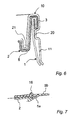
- the screw cap 10 is placed on the can 1 like a lid plugged in, with a number of clips 20, z. B. three resilient indentations, the edge fold 3 engages behind (Fig. 6).
- a projecting ring corrugation 21 engages the groove 8 a to the rotary sliding wall 13 resilient and thus close to the top wall 2 when the twist lock is rotated.
- the twist lock 10 is thereby made particularly handy that the ring wall 11 corrugated or is corrugated.
- the front 16a of the bead-like projection 16 and to rubberize the underside of the wall 13 at 13a or to be provided with another sealing coating.
- the bead-like projection 16 In the starting position or delivery position of the can is the bead-like projection 16 within the bounded area 5 in overlap with the edge area 6a. In this starting position, the projection 17 engages in the Dent 7a and fixes this starting position.
- the bead-like projection 16 By Pressing with the thumb on the bead-like projection 16 can to weaken the notches 6 in the area 6a bring, as shown in Fig. 5 top left. Subsequently one encompasses the edge 11, 12 of the twist lock 10 and turns it counterclockwise in Fig. 4.
- the bead 16 then increasingly bends the delimited area 5 as a flap 5a down, as in the illustration of FIG. 5 top right and sketched lower left. This will make the drinking or Pouring opening 9 formed, which is approximately the delimited area 5 occupies.
- the sealing coating comes in this closed position 16a of the bead 16 in contact with the edge 2a of the opening 9, as shown in Fig. 5 bottom left, and the Coating 13a seals against wall 2.
- Fig. 7 shows the interaction of the bead 16 with the bounded area 5 without using the thumb.
- the bounded area has three zones 5a, 5c and 5d with Inclined surfaces and a plateau zone 5b. If the Screw cap is turned from the starting position, the bead 16 slides in the direction along the inclined surface 5a onto the plateau surface 5b, whereby the pressure on the cover 2 increases and the line of weakness in the border area between 6c and 6a. This crack continues over area 6a in the area 6d and passes through the area 6b in the Region 6c in which the line of weakness is interrupted, so that the separated part 5 sticks to the lid 2 and does not fall inside the container.
- the steeper the Zone 5a is inclined the greater the initial force to tear the line of weakness cause.
- the inclined angle of the inclined surface is between 20 and 40 °.
- the screw cap 10 is preferably so dimensioned that the can base of a neighboring box in the upper Edge opening of the lid 10 fits in, so that several cans are stackable one above the other in mutual engagement.
- the weakening notch 6 has a kidney-shaped outline with a bulge 6e, at which point the Weakening notch is interrupted.
- the bounded area 5 the lid wall 2 is used to form the drinking opening 9 broken out, but remains in area 5e on the top wall hang to be captive.
- the eruption of the bounded area 5 is carried out in a similar manner as in the first embodiment, however, the inclined surface 5a is a bit narrower and longer compared to the Sloping surface of the first embodiment.
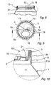
- the projection 16 of the Lid twist lock 10 is accordingly in the radial direction shorter and extends from the rotary sliding wall 13 only to below, d. H. it is designed as a dent or beading that a certain distance S1 (Fig.
- the distance of the dent or bead 16 from the Axis of rotation 4 is referred to as S2.
- the indentation of the The kidney shape has a certain distance S4 from the axis of rotation 4 of the rotating lid lock 10 and a distance S3 to the edge the top wall 2.
- S4 from the axis of rotation 4 of the rotating lid lock 10
- S3 to the edge the top wall 2.
- the closed one overlaps Half of the rotary sliding wall 13 the opening or the area 5, which is a maximum of half the area of the rotating sliding wall could take 13. Since you rounded the drinking opening 9 with Wants edges, and since the wall cut-out hang on web 5e is to remain the maximum size of the drinking opening 9 accordingly smaller. Since the drinking opening 9 is sealed sealing surface around the opening is required. The distances S1, S3 and S4 are therefore required. In the described embodiment have the openings 9 and 15th almost reached its maximum size for practice. you could the openings 9 and 15 only something increase that the distance S2 of the projection 16 from the The axis of rotation 4 is enlarged, as a result of which the outlines of the openings 9 and 15 can be designed somewhat oblong.
- the radial width of the opening 9 or 15 is r - (S3 + S4), if r means the radius of the rotating sliding wall.
- This radial Width should be at least r / 2 to be sufficient large drinking opening with standard beverage cans from To achieve 65 mm diameter.
- the projection 16 should be extend approximately tangentially to the breaking line 6 and the Cover area 5 approximately in the middle. This means, that the direction of extension of the projection 16 is an angle from about 30 ° to 60 ° to the radial beam when the Ratios of FIGS. 8 to 13 are considered.
- a range from 0.3 to 0.6 r is preferred.
- the screw cap 10 is opened in the same way clipped the top end of the can like the first one Embodiment.
- the circumferential ring wall 11 ends with a crimp 11a, as shown in Fig. 10.
- the ring wall 11 may have a wave shape in order turn the rotating lid lock 10 with greater force can.
- FIG. 11 shows the handling of the Cover turn lock outlined.
- Fig. 11 shows the position of the screw cap 10 after assembly in the Short position. If the customer wants to open the can, turn it he turn the lid 10 to the left, as through the Arrow P1 indicated. The projection 16 wanders over that oblique field 5a, the increasing pressure ensuring that the notch 6 tears. With this rotation P1 the Opening 15 in the delimited area 5 and covered finally this entirely, as shown in Fig. 12. at this rotation according to the arrow P1 pivots the wall region 5 inside the box 1, but remains on the top wall 2 hang as shown at 5e. In the position of FIG. 12 the drinking opening 9 is opened to the maximum.
- the twist lock can be turned by rotating the part 10 right again according to arrow P2. You then get to the position of the screw cap 13. The projection 16 arrives in contact with it the edge of the open area 5. Therefore the Angular position of the twist lock 10 slightly different from the angular position in the starting position of Fig. 11. A crescent-shaped area 2b is therefore covered by the top wall 2 visible, which was still covered in the position of FIG. 11. This crescent-shaped area 2b can be marked to the Inform informed that the can has been opened or that an attempt to open has taken place.
- the characteristic of the guarantee closure can also be realized in other ways, for example by means of a seal which is placed on the Cover wall 2 and the rotary sliding wall 13 in the area of Opening 15 is glued. If the rotating lid lock 10 is rotated, this seal must be torn what the indicates unauthorized use of the can.
- the security feature can also be in the area of the edge 11a of the ring wall 11, since there too when turning of the closure 10 a relative displacement to the can 1 takes place.
- the Pouring opening has a round cross section, for example because you have a pouring tap or want to put the like.
- the variant according to FIGS. 14 to 16 shows such a circular access opening 15
- Break lines 6 run approximately in the shape of a horseshoe and enclose a correspondingly designed area 5 around the a bead-starting sealing area 5f extends.
- the projection 16 moves over the inclined surface 5a and presses down the wall area 5 so that the predetermined breaking line 6 enters, except for area 5e, which remains.
- a projection 17 is provided, which in a corresponding Dents of the cover wall 2 snap into place, as is similar at 7a in Fig.
- Fig. 15 shows the open position of the container, the by turning according to arrow P2 to the right into the 16 can be transferred. Out This can be done by rotating the container Rotary lid lock 10 to the left according to arrow P3 be opened repeatedly.
- Box 1 can be further developed as a music box, in which a microchip with micro energy source and Micro speaker on the lid or lid lock attached when opening the can or when turning of the screw cap and a melody, plays an advertising message or the like.
- the new screw cap can also be used for other forms of containers or vessels are used which have a rotationally symmetrical wall with a top wall, which must be torn open to form a pouring opening.
- the new twist lock is very easy to use.
- the hood-like design of the twist lock enables comfortable gripping without risk of injury (i.e. without Breaking off the fingernails, no cutting on yourself Tear ring, as with previous containers).
- the Twist lock also offers favorable leverage, because the handle 11 further outside relative to the Actuation point 6/16 is located. Because of the simple Construction is the additional cost of the screw cap compared to the usual containers with pull tabs only slightly higher and are achievable by the Advantages weighed.
- the can can be opened and opened repeatedly be closed, it is leakproof and seals against the loss of carbonated beverages. at sealed can eliminates the risk of swallowing Insects that have fallen into the opened container could (exclusion of warranty claims).
Landscapes
- Engineering & Computer Science (AREA)
- Mechanical Engineering (AREA)
- Closures For Containers (AREA)
- Load-Engaging Elements For Cranes (AREA)
- Cookers (AREA)
- Containers Opened By Tearing Frangible Portions (AREA)
- Clamps And Clips (AREA)
- Centrifugal Separators (AREA)
- Refuse Receptacles (AREA)
Description
- Fig. 1
- einen Schnitt durch den Oberteil einer Dose mit Drehverschluss in auseinandergezogener Stellung,
- Fig. 2
- die Ansicht der Deckelwand der Dose, gegenüber Fig. 1 vergrößert,
- Fig. 3
- einen Schnitt entlang der Linie III-III in Fig. 2,
- Fig. 4
- die Ansicht eines Drehverschlusses,
- Fig. 5
- schematische Darstellungen des Öffnungsvorganges der Dose,
- Fig. 6
- eine Klipsausbildung,
- Fig. 7
- eine vergrößerte Einzelheit, geschnitten,
- Fig. 8
- einen Schnitt durch das Oberteil einer zweiten Ausführungsform der Dose mit Drehverschluss,
- Fig. 9
- eine Ansicht von oben der Dose nach Fig. 8,
- Fig. 10
- eine vergrößerte Einzelheit aus Fig. 8,
- Fig. 11 bis 13
- Öffnen und Schließen der Dose und
- Fig. 14 bis 13
- bis 16 Öffnen und Schließen einer Variante der Dose.
Claims (10)
- Behälter, umfassend:einen drehsymmetrischen Wandbereich (1);eine Deckelwand (2), die einen kreisförmigen Umfang mit einer gegebenen Radiuslänge (r) aufweist und an dem drehsymmetrischen Wandbereich (1) entlang des Umfangs angebracht ist;einen umgrenzten Bereich (5) der Deckelwand (2), der sich zwischen der Drehachse (4) und dem kreisförmigen Umfang der Deckelwand (2), und zwar mit etwas Abstand (S4) von der Drehachse (4) und etwas Abstand (S3) von dem kreisförmigen Umfang erstreckt und von einer Sollbruchlinie (6) umgeben ist, die nach Aufreissen eine einzige Trink- und Ausgießöffnung (9) freigibt;eine Einbuchtung mit Schrägfläche (5a), die von Wandteilen der Deckelwand (2) innerhalb der Sollbruchlinie (6) gebildet wird;einen Deckeldrehverschluss (10), der eine die Deckelwand (2) überspannende Wand (13), eine darin ausgesparte Öffnung (15) und einen Vorsprung (16) zum Aufreiten auf der Schrägfläche aufweist, um die Trink- und Ausgießöffnung (9) aufzureissen, wobei die ausgesparte Öffnung (15) weitgehend die Form und Größe des umgrenzten Bereichs (5) der Deckelwand (2) aufweist und durch Drehen des Deckeldrehverschlusses (10) mit diesem Bereich (5) zur Deckung gebracht werden kann;Mittel (3, 20). zum Abstützen des Deckeldrehverschlusses (10), wenn dieser zum Aufreissen der Trink- und Ausgießöffnung (9) um die Drehachse (4) gedreht wird, gekennzeichnet durch folgende Merkmale:die Einbuchtung mit Schrägfläche (5a) der Deckelwand (2) ist an solcher Stelle des umgrenzten Bereichs (5) angeordnet, die von der ausgesparten Öffnung (15) überdeckt wird, wenn der Deckeldrehverschluss (10) zur Freigabe der Trink- und Ausgießöffnung (9) gedreht worden ist;der Vorsprung (16) ist aus Wandteilen des Deckeldrehverschlusses (10) gebildet;die Wand (13) des Deckeldrehverschlusses (10) liegt federnd und mit Anpressung an der Oberseite der Deckelwand (2) an, um nach Aufreissen der Trink- und Ausgießöffnung (9) und Zurückdrehen des Deckeldrehverschlusses (10) die Trink- und Ausgießöffnung (9) abzudichten.
- Behälter nach Anspruch 1,
dadurch gekennzeichnet, dass der Abstand (S4) des Vorsprungs (16) von der Drehachse (4) im Bereich von 0,3 bis 0,6 r Radiuslänge der Deckelwand (2) liegt und daß die radiale Abmessung der Trink- und Ausgießöffnung (9) wenigstens die halbe Radiuslänge (r/2) beträgt. - Behälter nach Anspruch 1 oder 2,
dadurch gekennzeichnet, daß der drehsymmetrische Wandbereich (1) mit der Deckelwand (2) über eine Randfalzung (3) verbunden ist und der Deckeldrehverschluss (10) haubenförmig und zum Umgreifen der Randfalzung (3) ausgebildet ist, wobei die Abstützmittel (3, 20) gebildet werden, und dass der Deckeldrehverschluss (10) einen Griffbereich (11) aufweist, der relativ zur Drehachse (4) eine größere Hebellänge besitzt als der Abstand des Vorsprungs (16) von der Drehachse (4) ausmacht. - Behälter nach Anspruch 3,
dadurch gekennzeichnet, dass eine Anzahl Klipse (20) zum Umgreifen der Randfalzung (3) vorgesehen sind. - Behälter nach Anspruch 3 oder 4,
dadurch gekennzeichnet, dass der Griffbereich (11) des Deckeldrehverschlusses (10) gewellt ist. - Behälter nach einem der Ansprüche 1 bis 4,
dadurch gekennzeichnet, dass an der Deckelwand (2) und dem Deckeldrehverschluss (10) zusammenwirkende Rastmittel (7, 17) angebracht sind, um den Deckeldrehverschluss in der kompletten Öffnungsstellung oder in der vollständigen Schließstellung zu arretieren. - Behälter nach einem der Ansprüche 1 bis 6,
dadurch gekennzeichnet, dass die Umrandung des umgrenzten Bereichs (5) der Deckelwand mit einem abdichtenden Auftrag (5f) oder einer Beschichtung versehen ist. - Behälter nach einem der Ansprüche 1 bis 7,
dadurch gekennzeichnet, dass der umgrenzte Bereich (5) nierenförmigen Umriss aufweist. - Behälter nach einem der Ansprüche 1 bis 8,
dadurch gekennzeichnet, dass die Sollbruchlinie (6) nicht vollständig geschlossen ist, so dass beim Öffnen das Wandmaterial (5e) des umgrenzten Bereichs (5) als Lappen unverlierbar an der Deckelwand (2) hängenbleibt. - Behälter nach einem der Ansprüche 1 bis 9,
dadurch gekennzeichnet, dass der Deckeldrehverschluss (10) eine Ringwellung (21) aufweist, um die Drehschiebewand (13) federnd auf die Deckelwand (2) zu drücken.
Applications Claiming Priority (3)
| Application Number | Priority Date | Filing Date | Title |
|---|---|---|---|
| DE20004152U DE20004152U1 (de) | 2000-03-08 | 2000-03-08 | Dose mit Drehverschluss |
| DE20004152U | 2000-03-08 | ||
| PCT/EP2001/002361 WO2001066431A2 (de) | 2000-03-08 | 2001-03-02 | Behälter mit drehverschluss |
Publications (2)
| Publication Number | Publication Date |
|---|---|
| EP1265792A2 EP1265792A2 (de) | 2002-12-18 |
| EP1265792B1 true EP1265792B1 (de) | 2004-06-09 |
Family
ID=7938363
Family Applications (1)
| Application Number | Title | Priority Date | Filing Date |
|---|---|---|---|
| EP01915312A Expired - Lifetime EP1265792B1 (de) | 2000-03-08 | 2001-03-02 | Behälter mit drehverschluss |
Country Status (21)
| Country | Link |
|---|---|
| US (1) | US6910598B2 (de) |
| EP (1) | EP1265792B1 (de) |
| JP (1) | JP3672872B2 (de) |
| KR (1) | KR20020086619A (de) |
| CN (1) | CN1189362C (de) |
| AT (1) | ATE268723T1 (de) |
| AU (2) | AU2001242443B2 (de) |
| BR (1) | BR0108636B1 (de) |
| CA (1) | CA2401521C (de) |
| CZ (1) | CZ294290B6 (de) |
| DE (2) | DE20004152U1 (de) |
| ES (1) | ES2220740T3 (de) |
| HU (1) | HUP0300884A2 (de) |
| MX (1) | MXPA02008563A (de) |
| PL (1) | PL204164B1 (de) |
| RU (1) | RU2252182C2 (de) |
| SK (1) | SK286242B6 (de) |
| TR (1) | TR200401401T4 (de) |
| WO (1) | WO2001066431A2 (de) |
| YU (1) | YU66102A (de) |
| ZA (1) | ZA200206355B (de) |
Cited By (2)
| Publication number | Priority date | Publication date | Assignee | Title |
|---|---|---|---|---|
| RU2412878C2 (ru) * | 2005-12-20 | 2011-02-27 | Болл Пэкэджинг Юроп Гмбх | Емкость с крышкой для упаковывания текучих продуктов |
| DE102011101609A1 (de) | 2011-05-14 | 2012-11-15 | Bruno Ackermann | Wiederverschließbarer Behälter / Getränkedose |
Families Citing this family (42)
| Publication number | Priority date | Publication date | Assignee | Title |
|---|---|---|---|---|
| DE20114741U1 (de) * | 2001-09-07 | 2003-01-30 | Ackermann, Bruno, 55268 Nieder-Olm | Behälter mit Drehverschluß |
| DE10229257C1 (de) * | 2002-06-28 | 2003-04-17 | Dittrich & Co | Verschluß für Behälter, insbesondere für Flaschen |
| NL1021536C1 (nl) * | 2002-09-26 | 2004-03-29 | Bound2B B V | Inrichting voor het houden van vloeistoffen, in het bijzonder dranken. |
| DE60333313D1 (de) * | 2002-11-29 | 2010-08-19 | Onoda Shigeyoshi | Verschluss für dosengetränk |
| US20050029264A1 (en) * | 2003-08-04 | 2005-02-10 | Werth Elmer D. | Bottom-Fill Container and Opening System |
| US7475787B2 (en) * | 2005-10-28 | 2009-01-13 | Pepsico, Inc. And Silgan Plastics, Inc. | Induction heatable container with protective end caps |
| GB0522963D0 (en) * | 2005-11-11 | 2005-12-21 | Parker Julian | Container end and opener |
| PL208732B1 (pl) * | 2006-10-23 | 2011-06-30 | Invento Społka Z Ograniczoną Odpowiedzialnością | Pokrywka pojemnika zwłaszcza na napoje |
| DE102006051409A1 (de) * | 2006-10-27 | 2008-04-30 | C-A-P Technologies Gmbh | Verpackung für rieselfähige oder fließfähige Produkte |
| PT2254802E (pt) * | 2008-03-27 | 2012-08-28 | Xolution Gmbh | Fecho para uma embalagem |
| EP2396233B9 (de) * | 2009-02-11 | 2014-04-23 | Michael Keigan Jensen | Deckel zum öffnen und schliessen von dosen |
| AT508082B1 (de) * | 2009-04-07 | 2011-01-15 | Xolution Gmbh | Wiederverschliessbarer verschluss eines flüssigkeitsbehälters |
| DE102009002726B3 (de) * | 2009-04-29 | 2010-07-08 | Kunststofftechnik Waidhofen An Der Thaya Gmbh | Wiederverschließbarer Verschluss sowie Getränkedose und Getränkekarton |
| DE102009032106A1 (de) * | 2009-07-08 | 2011-01-13 | 4Pack Gmbh | Kappe für einen Getränkebehälter |
| KR200454700Y1 (ko) * | 2009-11-19 | 2011-07-25 | 조용현 | 원터치 손잡이와 회전 개폐구 어셈블리를 가지는 알루미늄 캔 |
| USD671834S1 (en) | 2011-01-07 | 2012-12-04 | Ball Corporation | Closure |
| CH704759A1 (de) * | 2011-03-29 | 2012-10-15 | Pi Design Ag | Behälterverschluss. |
| US8720717B2 (en) | 2012-02-02 | 2014-05-13 | Ball Corporation | End closure with full panel opening |
| AT513017B1 (de) * | 2012-06-06 | 2015-03-15 | Seibersdorf Labor Gmbh | Dose |
| USD1033215S1 (en) | 2012-08-10 | 2024-07-02 | Daniel A. Zabaleta | Container lid comprising frustum shaped sidewall and seaming chuck receiving radius |
| USD828753S1 (en) | 2012-08-10 | 2018-09-18 | Daniel A Zabaleta | Axially oriented peripheral sidewalled beverage container lid |
| US10968010B1 (en) | 2012-08-10 | 2021-04-06 | Daniel A Zabaleta | Resealable container lid and accessories including methods of manufacture and use |
| USD795693S1 (en) | 2012-08-10 | 2017-08-29 | Daniel A Zabeleta | Axially oriented peripheral sidewalled beverage container lid |
| US8844761B2 (en) | 2012-08-10 | 2014-09-30 | Daniel A. Zabaleta | Resealable beverage containers and methods of making same |
| USD1033216S1 (en) | 2012-08-10 | 2024-07-02 | Daniel A. Zabaleta | Container cap having frustum shaped sidewall segment enabling nesting |
| US8985371B2 (en) | 2012-08-10 | 2015-03-24 | Daniel A. Zabaleta | Resealable beverage containers and methods of making same |
| US12365511B1 (en) | 2012-08-10 | 2025-07-22 | Daniel A Zabaleta | Sealing cap having tamper evidence ring for sealing resealable container and method of use |
| US9637269B1 (en) | 2012-08-10 | 2017-05-02 | Daniel A. Zabaleta | Resealable container lid and accessories including methods of manufacturing and use |
| EP2913276A1 (de) * | 2014-02-27 | 2015-09-02 | Estavayer Lait SA | Plastikdose und ihr Herstellungsverfahren |
| CN106132837B (zh) | 2014-03-07 | 2019-05-14 | 鲍尔公司 | 具有大开口环状拉片的端盖 |
| US10632520B2 (en) | 2014-03-07 | 2020-04-28 | Ball Corporation | End closure with large opening ring pull tab |
| JP6402377B2 (ja) * | 2014-07-31 | 2018-10-10 | ライオン株式会社 | キャップ |
| JP6513829B2 (ja) * | 2015-04-20 | 2019-05-15 | エスエヌエステック リミテッド ライアビリティ カンパニー | 容器のための閉鎖システム |
| US20170027350A1 (en) * | 2015-07-28 | 2017-02-02 | Gustav Paulig Ltd | Lid for a drinking container and the drinking container |
| SE542046C2 (en) * | 2016-05-23 | 2020-02-18 | A & R Carton Lund Ab | A lid component provided with stacking members and a paperboard packaging container provided with such lid component |
| PL241515B1 (pl) * | 2019-04-11 | 2022-10-17 | Reend Spolka Z Ograniczona Odpowiedzialnoscia | Pokrywa pojemnika zwłaszcza na napoje |
| US12384594B2 (en) | 2021-04-05 | 2025-08-12 | Daniel A. Zabaleta | Threaded container components having frustum shaped surfaces enabling nesting |
| US11767152B2 (en) | 2021-06-29 | 2023-09-26 | Iv Thought Products And Design Corp. | Re-sealing vacuum package receptacle |
| US11565846B1 (en) | 2021-07-16 | 2023-01-31 | Randy D. Sines | Rotatable beverage can cover |
| USD953860S1 (en) | 2021-07-16 | 2022-06-07 | Randy D. Sines | Beverage can cover |
| ES2968273A1 (es) * | 2022-10-06 | 2024-05-08 | Galbany Lluis Ballus | Tapa para lata de bebida y sistema de abertura a presión |
| DE102023107869A1 (de) * | 2023-03-28 | 2024-10-02 | Top Cap Holding Gmbh | Dosendeckel |
Family Cites Families (24)
| Publication number | Priority date | Publication date | Assignee | Title |
|---|---|---|---|---|
| US3708091A (en) * | 1970-08-05 | 1973-01-02 | Steel Corp | Can end with bonded seal slide |
| US3726432A (en) * | 1971-02-05 | 1973-04-10 | F Gentile | Easy opening container |
| US3924777A (en) * | 1974-02-01 | 1975-12-09 | Continental Can Co | Non-detachable easy open flap and tab assembly |
| US3949898A (en) * | 1974-02-01 | 1976-04-13 | Continental Can Company, Inc. | Non-detachable easy open flap and tab assembly |
| US4125203A (en) * | 1977-05-23 | 1978-11-14 | Janos Sovari | Twist can top |
| US4821912A (en) * | 1982-08-23 | 1989-04-18 | Wells Robert A | Reclosable self-opening can end |
| DE8230293U1 (de) * | 1982-10-28 | 1982-12-16 | Jörgens & Möller Metall- und Kunststoff-Verarbeitungsgesellschaft mbH, 5620 Velbert | Getraenkedose |
| US4749100A (en) * | 1986-09-02 | 1988-06-07 | Ray Eberhart | Sanitary lid for beverage cans |
| PT86049A (pt) * | 1986-11-06 | 1988-12-15 | Astra Plastique | Tampa para recipiente inicialmente fechado com operculo perfuravel |
| NL8801179A (nl) * | 1988-05-04 | 1989-12-01 | Thomassen & Drijver | Blikdeksel. |
| US4938379A (en) * | 1988-12-23 | 1990-07-03 | Kellner Louis W | Cover for a beverage can |
| US5269432A (en) * | 1993-04-19 | 1993-12-14 | Beckertgis Nicholas G | Insect-proof and tamper-evident cover for beverage container |
| DE4427812A1 (de) * | 1994-07-26 | 1996-02-01 | Ljubomir Gantschev | Behälter mit einen variablen Deckeldrehverschluß |
| DE29511368U1 (de) * | 1995-07-14 | 1995-09-14 | Fackelmann GmbH + Co, 91217 Hersbruck | Getränkedosenverschluß |
| FR2738550B1 (fr) * | 1995-09-11 | 1997-11-07 | Biodome | Dispositif d'obturation d'un recipient lui-meme ferme, ensemble pour dispenser un produit comprenant un tel recipient et un tel dispositif d'obturation |
| US5692633A (en) * | 1996-01-02 | 1997-12-02 | Hullko Corporation | Beverage container lid |
| DE19613256B4 (de) * | 1996-04-02 | 2005-02-03 | Ball Packaging Europe Gmbh | Wiederverschließbarer Deckel aus Blech für einen Getränkedosenrumpf |
| US5816427A (en) * | 1996-07-16 | 1998-10-06 | Beckertgis; Nicholas G. | Insect-proof and tamper-evident cover for beverage container |
| DE19643487A1 (de) * | 1996-09-18 | 1998-03-19 | Cetoni Umwelttech Entw Gmbh | Behälter, sowie Verschluß für einen solchen Behälter |
| DE19706112C2 (de) * | 1996-10-10 | 2002-02-21 | Michael N Cagan | Getränkedose |
| CA2281601C (en) * | 1997-02-17 | 2008-04-22 | Frank Klose | Drinks can lid with closure cap |
| DE29703776U1 (de) * | 1997-03-03 | 1997-05-22 | Roschenzow, Gerhard, 90439 Nürnberg | Hygienischer Verschluß für Behälter, wie Flaschen, Dosen o.dgl. zum Aufnehmen, Wiedergeben und/oder Aufbewahren von Flüssigkeiten, wie Getränken, Medikamenten u.a. |
| IT1309418B1 (it) * | 1998-06-24 | 2002-01-23 | Giuseppe Arturelli | Manufatto in plastica per garantire l'igiene delle lattine inalluminio per bevande. |
| ES1040791Y (es) * | 1998-07-27 | 1999-09-01 | Gonzalez Carrete Benjamin | Dispositivo protector para el consumo de productos enlatados, tales como bebidas, conservas y otros. |
-
2000
- 2000-03-08 DE DE20004152U patent/DE20004152U1/de not_active Expired - Lifetime
-
2001
- 2001-03-02 TR TR2004/01401T patent/TR200401401T4/xx unknown
- 2001-03-02 YU YU66102A patent/YU66102A/sh unknown
- 2001-03-02 HU HU0300884A patent/HUP0300884A2/hu unknown
- 2001-03-02 BR BRPI0108636-7A patent/BR0108636B1/pt not_active IP Right Cessation
- 2001-03-02 AU AU2001242443A patent/AU2001242443B2/en not_active Ceased
- 2001-03-02 AT AT01915312T patent/ATE268723T1/de active
- 2001-03-02 JP JP2001565259A patent/JP3672872B2/ja not_active Expired - Fee Related
- 2001-03-02 ES ES01915312T patent/ES2220740T3/es not_active Expired - Lifetime
- 2001-03-02 RU RU2002126603/12A patent/RU2252182C2/ru not_active IP Right Cessation
- 2001-03-02 SK SK1266-2002A patent/SK286242B6/sk unknown
- 2001-03-02 KR KR1020027011755A patent/KR20020086619A/ko not_active Ceased
- 2001-03-02 CN CNB018060692A patent/CN1189362C/zh not_active Expired - Fee Related
- 2001-03-02 PL PL363049A patent/PL204164B1/pl not_active IP Right Cessation
- 2001-03-02 US US10/221,281 patent/US6910598B2/en not_active Expired - Fee Related
- 2001-03-02 CZ CZ20022907A patent/CZ294290B6/cs not_active IP Right Cessation
- 2001-03-02 AU AU4244301A patent/AU4244301A/xx active Pending
- 2001-03-02 EP EP01915312A patent/EP1265792B1/de not_active Expired - Lifetime
- 2001-03-02 WO PCT/EP2001/002361 patent/WO2001066431A2/de not_active Ceased
- 2001-03-02 CA CA002401521A patent/CA2401521C/en not_active Expired - Fee Related
- 2001-03-02 MX MXPA02008563A patent/MXPA02008563A/es active IP Right Grant
- 2001-03-02 DE DE50102535T patent/DE50102535D1/de not_active Expired - Lifetime
-
2002
- 2002-08-08 ZA ZA200206355A patent/ZA200206355B/en unknown
Cited By (3)
| Publication number | Priority date | Publication date | Assignee | Title |
|---|---|---|---|---|
| RU2412878C2 (ru) * | 2005-12-20 | 2011-02-27 | Болл Пэкэджинг Юроп Гмбх | Емкость с крышкой для упаковывания текучих продуктов |
| DE102011101609A1 (de) | 2011-05-14 | 2012-11-15 | Bruno Ackermann | Wiederverschließbarer Behälter / Getränkedose |
| WO2012156068A1 (de) | 2011-05-14 | 2012-11-22 | Dieter Folland | Wiederverschliessbarer behälter/getränkedose |
Also Published As
| Publication number | Publication date |
|---|---|
| US20030155360A1 (en) | 2003-08-21 |
| YU66102A (sh) | 2003-10-31 |
| JP2003525824A (ja) | 2003-09-02 |
| US6910598B2 (en) | 2005-06-28 |
| CZ294290B6 (cs) | 2004-11-10 |
| PL204164B1 (pl) | 2009-12-31 |
| MXPA02008563A (es) | 2004-08-23 |
| CN1189362C (zh) | 2005-02-16 |
| CA2401521C (en) | 2007-12-11 |
| SK12662002A3 (sk) | 2003-01-09 |
| WO2001066431A2 (de) | 2001-09-13 |
| RU2252182C2 (ru) | 2005-05-20 |
| CA2401521A1 (en) | 2001-09-13 |
| TR200401401T4 (tr) | 2004-07-21 |
| AU4244301A (en) | 2001-09-17 |
| DE20004152U1 (de) | 2001-07-19 |
| ZA200206355B (en) | 2003-08-08 |
| ES2220740T3 (es) | 2004-12-16 |
| WO2001066431B1 (de) | 2002-05-30 |
| WO2001066431A3 (de) | 2002-02-07 |
| ATE268723T1 (de) | 2004-06-15 |
| EP1265792A2 (de) | 2002-12-18 |
| AU2001242443B2 (en) | 2004-09-02 |
| JP3672872B2 (ja) | 2005-07-20 |
| SK286242B6 (sk) | 2008-06-06 |
| KR20020086619A (ko) | 2002-11-18 |
| CN1411416A (zh) | 2003-04-16 |
| DE50102535D1 (de) | 2004-07-15 |
| BR0108636B1 (pt) | 2012-10-30 |
| CZ20022907A3 (cs) | 2003-10-15 |
| HUP0300884A2 (hu) | 2003-08-28 |
| PL363049A1 (en) | 2004-11-15 |
| BR0108636A (pt) | 2002-12-17 |
Similar Documents
| Publication | Publication Date | Title |
|---|---|---|
| WO2001066431A2 (de) | Behälter mit drehverschluss | |
| EP4303149B1 (de) | Unverlierbarer verschluss mit stabilisiertem öffnungswinkel | |
| DE2306810A1 (de) | Dose mit eindruecklasche | |
| EP3898436B1 (de) | Dosendeckel, dose und verfahren zum herstellen eines dosendeckels | |
| DE20114741U1 (de) | Behälter mit Drehverschluß | |
| EP0524279B1 (de) | Kunststoffverschluss mit garantieelement | |
| WO2021018772A1 (de) | Unverlierbarer verschluss mit stabilisiertem öffnungswinkel | |
| DE2553835B2 (de) | Endwand für eine Dose | |
| DE60106413T2 (de) | Verschlusskappe für flaschen | |
| DE69505147T2 (de) | Getränkedose mit integriertem ausgiesser | |
| DE60126333T2 (de) | Öffnungsvorrichtung | |
| DE3923772A1 (de) | Leicht zu oeffnender deckel fuer getraenkedosen | |
| WO1998012118A2 (de) | Behälter, insbesondere getränkedose, sowie deckel für einen solchen behälter | |
| DE1432081C3 (de) | Behälter | |
| DE3201469A1 (de) | Wiederverschliessbarer metalldeckel fuer eine dose fuer fluessige fuellgueter | |
| DE102004038144B4 (de) | Verschlussvorrichtung für Behälter | |
| DE1607934A1 (de) | Aufreissdose | |
| DE2659243A1 (de) | Flaschenaufreiss-verschlusskappe | |
| EP1507714B1 (de) | Ausguss-verschluss für flüssigkeitspackungen | |
| DE19653065B4 (de) | Verpackung | |
| DE2832706A1 (de) | Deckel aus blech fuer behaelter mit im deckelspiegel vorgesehener aufreisslinie | |
| EP2262696A1 (de) | Verschlusskappe | |
| DE19508444A1 (de) | Deckel | |
| EP1174346A1 (de) | Konische Verpackung mit Entnahmeöffnung | |
| DE69809567T2 (de) | Verschlussdeckel für getränkedose mit aussenkappe |
Legal Events
| Date | Code | Title | Description |
|---|---|---|---|
| PUAI | Public reference made under article 153(3) epc to a published international application that has entered the european phase |
Free format text: ORIGINAL CODE: 0009012 |
|
| 17P | Request for examination filed |
Effective date: 20020824 |
|
| AK | Designated contracting states |
Kind code of ref document: A2 Designated state(s): AT BE CH CY DE DK ES FI FR GB GR IE IT LI LU MC NL PT SE TR |
|
| AX | Request for extension of the european patent |
Free format text: AL;LT;LV;MK;RO PAYMENT 20020824;SI PAYMENT 20020824 |
|
| GRAP | Despatch of communication of intention to grant a patent |
Free format text: ORIGINAL CODE: EPIDOSNIGR1 |
|
| GRAS | Grant fee paid |
Free format text: ORIGINAL CODE: EPIDOSNIGR3 |
|
| GRAA | (expected) grant |
Free format text: ORIGINAL CODE: 0009210 |
|
| AK | Designated contracting states |
Kind code of ref document: B1 Designated state(s): AT BE CH CY DE DK ES FI FR GB GR IE IT LI LU MC NL PT SE TR |
|
| AX | Request for extension of the european patent |
Extension state: RO SI |
|
| PG25 | Lapsed in a contracting state [announced via postgrant information from national office to epo] |
Ref country code: FI Free format text: LAPSE BECAUSE OF FAILURE TO SUBMIT A TRANSLATION OF THE DESCRIPTION OR TO PAY THE FEE WITHIN THE PRESCRIBED TIME-LIMIT Effective date: 20040609 |
|
| REG | Reference to a national code |
Ref country code: GB Ref legal event code: FG4D Free format text: NOT ENGLISH |
|
| REG | Reference to a national code |
Ref country code: CH Ref legal event code: EP |
|
| REG | Reference to a national code |
Ref country code: CH Ref legal event code: NV Representative=s name: BOVARD AG PATENTANWAELTE |
|
| GBT | Gb: translation of ep patent filed (gb section 77(6)(a)/1977) |
Effective date: 20040622 |
|
| REF | Corresponds to: |
Ref document number: 50102535 Country of ref document: DE Date of ref document: 20040715 Kind code of ref document: P |
|
| REG | Reference to a national code |
Ref country code: IE Ref legal event code: FG4D Free format text: GERMAN |
|
| PG25 | Lapsed in a contracting state [announced via postgrant information from national office to epo] |
Ref country code: DK Free format text: LAPSE BECAUSE OF FAILURE TO SUBMIT A TRANSLATION OF THE DESCRIPTION OR TO PAY THE FEE WITHIN THE PRESCRIBED TIME-LIMIT Effective date: 20040909 |
|
| REG | Reference to a national code |
Ref country code: SE Ref legal event code: TRGR |
|
| REG | Reference to a national code |
Ref country code: GR Ref legal event code: EP Ref document number: 20040402972 Country of ref document: GR |
|
| LTIE | Lt: invalidation of european patent or patent extension |
Effective date: 20040609 |
|
| REG | Reference to a national code |
Ref country code: ES Ref legal event code: FG2A Ref document number: 2220740 Country of ref document: ES Kind code of ref document: T3 |
|
| PG25 | Lapsed in a contracting state [announced via postgrant information from national office to epo] |
Ref country code: CY Free format text: LAPSE BECAUSE OF FAILURE TO SUBMIT A TRANSLATION OF THE DESCRIPTION OR TO PAY THE FEE WITHIN THE PRESCRIBED TIME-LIMIT Effective date: 20050302 Ref country code: LU Free format text: LAPSE BECAUSE OF NON-PAYMENT OF DUE FEES Effective date: 20050302 |
|
| ET | Fr: translation filed | ||
| PG25 | Lapsed in a contracting state [announced via postgrant information from national office to epo] |
Ref country code: MC Free format text: LAPSE BECAUSE OF NON-PAYMENT OF DUE FEES Effective date: 20050331 |
|
| PLBE | No opposition filed within time limit |
Free format text: ORIGINAL CODE: 0009261 |
|
| STAA | Information on the status of an ep patent application or granted ep patent |
Free format text: STATUS: NO OPPOSITION FILED WITHIN TIME LIMIT |
|
| 26N | No opposition filed |
Effective date: 20050310 |
|
| PG25 | Lapsed in a contracting state [announced via postgrant information from national office to epo] |
Ref country code: PT Free format text: LAPSE BECAUSE OF NON-PAYMENT OF DUE FEES Effective date: 20041109 |
|
| REG | Reference to a national code |
Ref country code: CH Ref legal event code: PFA Owner name: ACKERMANN, BRUNO Free format text: ACKERMANN, BRUNO#KOENIGSBERGER STRASSE 103#55268 NIEDER-OLM (DE) $ FOLLAND, DIETER#PFARRGASSE 32#65293 HOCHHEIM 2 (DE) $ GOETZ, HERMANN#WALTER-RATHENAU-STRASSE 39#65428 RUESSELSHEIM (DE) -TRANSFER TO- ACKERMANN, BRUNO#KOENIGSBERGER STRASSE 103#55268 NIEDER-OLM (DE) $ FOLLAND, DIETER#PFARRGASSE 32#65293 HOCHHEIM 2 (DE) $ GOETZ, HERMANN#WALTER-RATHENAU-STRASSE 39#65428 RUESSELSHEIM (DE) |
|
| PGFP | Annual fee paid to national office [announced via postgrant information from national office to epo] |
Ref country code: TR Payment date: 20120228 Year of fee payment: 12 |
|
| PGFP | Annual fee paid to national office [announced via postgrant information from national office to epo] |
Ref country code: IT Payment date: 20120327 Year of fee payment: 12 |
|
| PGFP | Annual fee paid to national office [announced via postgrant information from national office to epo] |
Ref country code: CH Payment date: 20130319 Year of fee payment: 13 Ref country code: DE Payment date: 20130326 Year of fee payment: 13 Ref country code: SE Payment date: 20130319 Year of fee payment: 13 Ref country code: FR Payment date: 20130329 Year of fee payment: 13 Ref country code: GB Payment date: 20130318 Year of fee payment: 13 Ref country code: IE Payment date: 20130315 Year of fee payment: 13 Ref country code: ES Payment date: 20130320 Year of fee payment: 13 |
|
| PGFP | Annual fee paid to national office [announced via postgrant information from national office to epo] |
Ref country code: GR Payment date: 20130319 Year of fee payment: 13 Ref country code: NL Payment date: 20130318 Year of fee payment: 13 |
|
| PGFP | Annual fee paid to national office [announced via postgrant information from national office to epo] |
Ref country code: AT Payment date: 20130318 Year of fee payment: 13 |
|
| PGFP | Annual fee paid to national office [announced via postgrant information from national office to epo] |
Ref country code: BE Payment date: 20130318 Year of fee payment: 13 |
|
| REG | Reference to a national code |
Ref country code: DE Ref legal event code: R119 Ref document number: 50102535 Country of ref document: DE |
|
| REG | Reference to a national code |
Ref country code: NL Ref legal event code: V1 Effective date: 20141001 |
|
| REG | Reference to a national code |
Ref country code: CH Ref legal event code: PL |
|
| REG | Reference to a national code |
Ref country code: SE Ref legal event code: EUG |
|
| REG | Reference to a national code |
Ref country code: AT Ref legal event code: MM01 Ref document number: 268723 Country of ref document: AT Kind code of ref document: T Effective date: 20140302 |
|
| GBPC | Gb: european patent ceased through non-payment of renewal fee |
Effective date: 20140302 |
|
| REG | Reference to a national code |
Ref country code: GR Ref legal event code: ML Ref document number: 20040402972 Country of ref document: GR Effective date: 20141002 |
|
| PG25 | Lapsed in a contracting state [announced via postgrant information from national office to epo] |
Ref country code: SE Free format text: LAPSE BECAUSE OF NON-PAYMENT OF DUE FEES Effective date: 20140303 |
|
| REG | Reference to a national code |
Ref country code: FR Ref legal event code: ST Effective date: 20141128 |
|
| REG | Reference to a national code |
Ref country code: IE Ref legal event code: MM4A |
|
| REG | Reference to a national code |
Ref country code: DE Ref legal event code: R119 Ref document number: 50102535 Country of ref document: DE Effective date: 20141001 |
|
| PG25 | Lapsed in a contracting state [announced via postgrant information from national office to epo] |
Ref country code: GR Free format text: LAPSE BECAUSE OF NON-PAYMENT OF DUE FEES Effective date: 20141002 Ref country code: DE Free format text: LAPSE BECAUSE OF NON-PAYMENT OF DUE FEES Effective date: 20141001 Ref country code: FR Free format text: LAPSE BECAUSE OF NON-PAYMENT OF DUE FEES Effective date: 20140331 Ref country code: CH Free format text: LAPSE BECAUSE OF NON-PAYMENT OF DUE FEES Effective date: 20140331 Ref country code: GB Free format text: LAPSE BECAUSE OF NON-PAYMENT OF DUE FEES Effective date: 20140302 Ref country code: LI Free format text: LAPSE BECAUSE OF NON-PAYMENT OF DUE FEES Effective date: 20140331 Ref country code: IE Free format text: LAPSE BECAUSE OF NON-PAYMENT OF DUE FEES Effective date: 20140302 |
|
| PG25 | Lapsed in a contracting state [announced via postgrant information from national office to epo] |
Ref country code: AT Free format text: LAPSE BECAUSE OF NON-PAYMENT OF DUE FEES Effective date: 20140302 Ref country code: NL Free format text: LAPSE BECAUSE OF NON-PAYMENT OF DUE FEES Effective date: 20141001 |
|
| PG25 | Lapsed in a contracting state [announced via postgrant information from national office to epo] |
Ref country code: IT Free format text: LAPSE BECAUSE OF NON-PAYMENT OF DUE FEES Effective date: 20140302 |
|
| REG | Reference to a national code |
Ref country code: ES Ref legal event code: FD2A Effective date: 20150427 |
|
| PG25 | Lapsed in a contracting state [announced via postgrant information from national office to epo] |
Ref country code: ES Free format text: LAPSE BECAUSE OF NON-PAYMENT OF DUE FEES Effective date: 20140303 |
|
| PG25 | Lapsed in a contracting state [announced via postgrant information from national office to epo] |
Ref country code: BE Free format text: LAPSE BECAUSE OF NON-PAYMENT OF DUE FEES Effective date: 20140331 |
|
| PG25 | Lapsed in a contracting state [announced via postgrant information from national office to epo] |
Ref country code: TR Free format text: LAPSE BECAUSE OF NON-PAYMENT OF DUE FEES Effective date: 20140302 |