EP1264681A1 - Wulsthalter - Anordnung und Verfahren zum Halten und Positionieren eines Reifenwulstes - Google Patents
Wulsthalter - Anordnung und Verfahren zum Halten und Positionieren eines Reifenwulstes Download PDFInfo
- Publication number
- EP1264681A1 EP1264681A1 EP02100567A EP02100567A EP1264681A1 EP 1264681 A1 EP1264681 A1 EP 1264681A1 EP 02100567 A EP02100567 A EP 02100567A EP 02100567 A EP02100567 A EP 02100567A EP 1264681 A1 EP1264681 A1 EP 1264681A1
- Authority
- EP
- European Patent Office
- Prior art keywords
- bead
- slide members
- tire
- setter
- chain
- Prior art date
- Legal status (The legal status is an assumption and is not a legal conclusion. Google has not performed a legal analysis and makes no representation as to the accuracy of the status listed.)
- Granted
Links
Images


Classifications
-
- B—PERFORMING OPERATIONS; TRANSPORTING
- B29—WORKING OF PLASTICS; WORKING OF SUBSTANCES IN A PLASTIC STATE IN GENERAL
- B29D—PRODUCING PARTICULAR ARTICLES FROM PLASTICS OR FROM SUBSTANCES IN A PLASTIC STATE
- B29D30/00—Producing pneumatic or solid tyres or parts thereof
- B29D30/06—Pneumatic tyres or parts thereof (e.g. produced by casting, moulding, compression moulding, injection moulding, centrifugal casting)
- B29D30/08—Building tyres
- B29D30/20—Building tyres by the flat-tyre method, i.e. building on cylindrical drums
- B29D30/32—Fitting the bead-rings or bead-cores; Folding the textile layers around the rings or cores
-
- B—PERFORMING OPERATIONS; TRANSPORTING
- B29—WORKING OF PLASTICS; WORKING OF SUBSTANCES IN A PLASTIC STATE IN GENERAL
- B29D—PRODUCING PARTICULAR ARTICLES FROM PLASTICS OR FROM SUBSTANCES IN A PLASTIC STATE
- B29D30/00—Producing pneumatic or solid tyres or parts thereof
- B29D30/0016—Handling tyres or parts thereof, e.g. supplying, storing, conveying
- B29D2030/0044—Handling tyre beads, e.g., storing, transporting, transferring and supplying to the toroidal support or to the drum
-
- B—PERFORMING OPERATIONS; TRANSPORTING
- B29—WORKING OF PLASTICS; WORKING OF SUBSTANCES IN A PLASTIC STATE IN GENERAL
- B29D—PRODUCING PARTICULAR ARTICLES FROM PLASTICS OR FROM SUBSTANCES IN A PLASTIC STATE
- B29D30/00—Producing pneumatic or solid tyres or parts thereof
- B29D30/06—Pneumatic tyres or parts thereof (e.g. produced by casting, moulding, compression moulding, injection moulding, centrifugal casting)
- B29D30/08—Building tyres
- B29D30/20—Building tyres by the flat-tyre method, i.e. building on cylindrical drums
- B29D30/32—Fitting the bead-rings or bead-cores; Folding the textile layers around the rings or cores
- B29D2030/3207—Positioning the beads
Definitions
- This invention relates to tire building and especially centering and placing a circular tire bead on a bead setter for application to a tire carcass built on a tire building drum.
- a bead or bead apex assembly is fabricated at a position away from the tire building drum and then applied to the plies which have been positioned on the tire building drum during revolutions of the drum.
- the bead or bead apex assembly is applied to the tire casing which has been built on the drum, it is important that the beads be set in a cylindrical configuration and in a centered position relative to the cylindrical drum on which the carcass is built. It has been found that this operation cannot be done manually with the necessary precision and therefore a tire bead holder is needed for gripping the circular tire bead and placing the bead in a circular condition at a concentric position on a bead setter.
- the present invention is directed to an improved tire bead holder assembly in which the bead holding fingers are moved simultaneously and equally in a radial direction to center and hold the bead or bead apex assembly.
- a direct drive chain is connected to radially moveable slides for supporting the fingers providing substantially equal centering forces on circumferentially spaced portions of the bead.
- a simple piston cylinder assembly connected to the chain drive provides the simultaneous movement of the fingers.
- a tire bead holder assembly for gripping a circular tire bead and placing the bead in a concentric position on a bead setter comprising a supporting disk, a plurality of circumferentially spaced radially extending linear guide members on the disk characterized by slide members mounted on each of the guide members, each of the slide members having an axially extending bead holding finger for engaging the bead and a radially moveable drive means in engagement with each of the slide members for moving each of the slide members and each axially extending finger radially into and out of engagement with the tire bead.
- a method of holding and positioning a tire bead for transfer to a bead setter from a bead holder comprising:
- a tire bead holder assembly 10 is shown supporting a bead 12 and apex 14 which have been fabricated at another location and hung over bead holding fingers 16 at circumferentially spaced positions around the bead holder assembly 10.
- a cover 18 is mounted on a supporting disk 20 and has slots 22 through which the fingers 16 extend.
- the fingers 16 are mounted on slide members 24 each of which is slidably mounted on a linear guide member 26 fastened to the disk 20 at circumferentially spaced positions in a radially extending direction.
- each of the slide members 24 may have a slot 28 with ribs 30 for sliding engagement with slide grooves 32 in the guide member for guiding the radial movement of the slide member 24.
- a chain 34 is guided by sprockets 36 over a drive path extending alongside each of the slide members 24 which are connected to the chains by clamps 38 to provide for simultaneous radial movement of the slide members and the fingers 16 as the chain 34 is moved by a suitable power means such as piston cylinder assembly 41 shown in Fig 3.
- a piston 43 of the assembly 41 is mounted on the disk 20 and the moveable cylinder 45 has a saddle member 47 with a hook 49 attached to a first end 51 of the chain 34 and an adjustable connection 53 connected to the second end 55 of the chain.
- Suitable connections to the piston cylinder assembly 41 provide for moving the cylinder 45 carrying the saddle 47 with the chain 34 between positions A and B causing the slide members 24 to move radially carrying the fingers 16 into engagement with the bead 12 by regulating the pressure in the cylinder 45.
- the force applied by the finger 16 to the bead 12 can be adjusted so that there is no distortion of the bead 12 and apex 14 as it is being grasped by the tire bead holder assembly 10.
- the fingers 16 are mounted on the slide members 24 by threading a socket 57 in each of the fingers over threaded studs 59 on the surface of the slide members 24.
- the studs 59 may be spaced radially for mounting the fingers 16 at different radii such as 13 inches (33.02 cm) and 17 inches (43.18 cm).
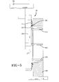
- the tire bead holder assembly 10 may be mounted on a suitable conveyor 61 shown schematically in Fig 5 for carrying the bead 12 and apex 14 into engagement with a bead setter 63 shown in section which may have magnets 65 for holding the bead 12 in a centered position ready for application to the tire building drum by the bead setter.
- a suitable conveyor 61 shown schematically in Fig 5 for carrying the bead 12 and apex 14 into engagement with a bead setter 63 shown in section which may have magnets 65 for holding the bead 12 in a centered position ready for application to the tire building drum by the bead setter.
- the fingers 16 may be retracted radially by actuating the piston cylinder assembly 43 and the bead holder assembly 10 may then be moved away from the bead setter.
Landscapes
- Engineering & Computer Science (AREA)
- Mechanical Engineering (AREA)
- Tyre Moulding (AREA)
Applications Claiming Priority (2)
| Application Number | Priority Date | Filing Date | Title |
|---|---|---|---|
| US874444 | 2001-06-05 | ||
| US09/874,444 US6623583B2 (en) | 2001-06-05 | 2001-06-05 | Bead holder |
Publications (2)
| Publication Number | Publication Date |
|---|---|
| EP1264681A1 true EP1264681A1 (de) | 2002-12-11 |
| EP1264681B1 EP1264681B1 (de) | 2005-01-19 |
Family
ID=25363786
Family Applications (1)
| Application Number | Title | Priority Date | Filing Date |
|---|---|---|---|
| EP02100567A Expired - Fee Related EP1264681B1 (de) | 2001-06-05 | 2002-05-28 | Wulsthalter - Anordnung und Verfahren zum Halten und Positionieren eines Reifenwulstes |
Country Status (4)
| Country | Link |
|---|---|
| US (1) | US6623583B2 (de) |
| EP (1) | EP1264681B1 (de) |
| BR (1) | BR0201967B1 (de) |
| DE (1) | DE60202642T2 (de) |
Cited By (3)
| Publication number | Priority date | Publication date | Assignee | Title |
|---|---|---|---|---|
| EP1474282B1 (de) * | 2001-12-27 | 2006-05-31 | Pirelli Pneumatici S.p.A. | Verfahren und vorrichtung für den reifenaufbau |
| EP2036705A1 (de) | 2007-09-15 | 2009-03-18 | Continental Aktiengesellschaft | Vorrichtung zum Positionieren eines Reifenkernes auf einer Reifenkarkasse für die Herstellung von Fahrzeugreifen |
| CN105711122A (zh) * | 2016-03-23 | 2016-06-29 | 厦门洪海机械有限公司 | 一种传递轮胎胎圈的预置装置 |
Families Citing this family (8)
| Publication number | Priority date | Publication date | Assignee | Title |
|---|---|---|---|---|
| JP4632650B2 (ja) * | 2003-10-07 | 2011-02-16 | 株式会社ブリヂストン | タイヤの製造方法およびプリセットビード成型装置ならびにプリセットビード成型システム |
| DE102005023925A1 (de) * | 2005-05-24 | 2006-11-30 | Continental Aktiengesellschaft | Verfahren und Vorrichtung einsetzbar im automatisiert ablaufenden Aufbau eines Fahrzeugluftreifens |
| JP4716384B2 (ja) * | 2005-12-07 | 2011-07-06 | 東洋ゴム工業株式会社 | タイヤ成型工程におけるビード供給装置 |
| US20090071606A1 (en) * | 2007-09-17 | 2009-03-19 | Steinke Richard A | Alignment system for positioning tire beads onto a tire core side wall |
| CN108174600B (zh) | 2015-10-14 | 2020-09-01 | 巴特尔机械系统有限公司 | 多台阶胎圈成型器 |
| US20170106617A1 (en) * | 2015-10-14 | 2017-04-20 | Bartell Machinery Systems, L.L.C. | Quick-change bead former |
| NL2015968B1 (en) | 2015-12-16 | 2017-06-30 | Vmi Holland Bv | Drum set for manufacturing a bead-apex for a tire and assembly comprising said tooling. |
| US11981101B2 (en) * | 2020-08-31 | 2024-05-14 | The Goodyear Tire & Rubber Company | Method and apparatus for forming an apex |
Citations (6)
| Publication number | Priority date | Publication date | Assignee | Title |
|---|---|---|---|---|
| US3700526A (en) * | 1970-02-11 | 1972-10-24 | Firestone Tire & Rubber Co | Tire building machine having means advancing a plurality of drums through a plurality of assembly stations |
| US4580958A (en) * | 1985-04-15 | 1986-04-08 | Nrm Corporation | Tire loader and basket |
| US4726861A (en) * | 1986-04-08 | 1988-02-23 | The Firestone Tire & Rubber Company | Method and device for automatically centering and feeding beads onto a tire building drum |
| US4950142A (en) * | 1988-01-27 | 1990-08-21 | Mitsubishi Jukogyo Kabushiki Kaisha | Green tire inserting apparatus in a tire vulcanizing machine |
| US5203938A (en) * | 1991-01-31 | 1993-04-20 | Heico Aluminum Products, Inc. | Method and apparatus for forming an apex filler and/or applying an apex filler to a bead ring sub-assembly |
| WO2000015422A1 (fr) * | 1998-09-14 | 2000-03-23 | Societe De Technologie Michelin | Dispositif de suspension de carcasses de pneumatiques |
Family Cites Families (12)
| Publication number | Priority date | Publication date | Assignee | Title |
|---|---|---|---|---|
| US3212951A (en) * | 1962-11-08 | 1965-10-19 | Goodrich Co B F | Adjustable band applier |
| GB1214832A (en) | 1967-03-17 | 1970-12-02 | Dunlop Co Ltd | Improvements in or relating to the manufacture of pneumatic tyres |
| US3849231A (en) | 1970-02-11 | 1974-11-19 | W Brey | Bead mechanism |
| BE786081A (fr) | 1971-07-13 | 1973-01-10 | Uniroyal Sa | Appareil et procede pour maintenir les tringles des bourrelets de pneu |
| US3909335A (en) | 1974-05-22 | 1975-09-30 | Gen Tire & Rubber Co | Pneumatic tire transporter |
| JPS57174236A (en) | 1981-04-20 | 1982-10-26 | Mitsubishi Heavy Ind Ltd | Feeder for tire molding machine |
| JPS587339A (ja) * | 1981-07-03 | 1983-01-17 | Yokohama Rubber Co Ltd:The | タイヤ成形装置におけるバンド及びビ−ドの移送供給装置 |
| US4604158A (en) | 1985-01-31 | 1986-08-05 | The Goodyear Tire & Rubber Company | Apparatus and method for storing and positioning bead cores for tire building |
| US4964931A (en) | 1989-04-04 | 1990-10-23 | The Goodyear Tire & Rubber Company | Tire bead setter apparatus and method |
| JP2810114B2 (ja) | 1989-06-03 | 1998-10-15 | 株式会社ブリヂストン | タイヤ成型装置 |
| JPH09201883A (ja) | 1996-01-25 | 1997-08-05 | Bridgestone Corp | フィラー付きビードの保持機構 |
| FR2755898A1 (fr) | 1996-11-21 | 1998-05-22 | Michelin & Cie | Fabrication d'un renforcement de carcasse pour pneumatique au moyen de deux demi-renforcements de carcasse |
-
2001
- 2001-06-05 US US09/874,444 patent/US6623583B2/en not_active Expired - Lifetime
-
2002
- 2002-05-28 BR BRPI0201967-1A patent/BR0201967B1/pt not_active IP Right Cessation
- 2002-05-28 EP EP02100567A patent/EP1264681B1/de not_active Expired - Fee Related
- 2002-05-28 DE DE60202642T patent/DE60202642T2/de not_active Expired - Lifetime
Patent Citations (6)
| Publication number | Priority date | Publication date | Assignee | Title |
|---|---|---|---|---|
| US3700526A (en) * | 1970-02-11 | 1972-10-24 | Firestone Tire & Rubber Co | Tire building machine having means advancing a plurality of drums through a plurality of assembly stations |
| US4580958A (en) * | 1985-04-15 | 1986-04-08 | Nrm Corporation | Tire loader and basket |
| US4726861A (en) * | 1986-04-08 | 1988-02-23 | The Firestone Tire & Rubber Company | Method and device for automatically centering and feeding beads onto a tire building drum |
| US4950142A (en) * | 1988-01-27 | 1990-08-21 | Mitsubishi Jukogyo Kabushiki Kaisha | Green tire inserting apparatus in a tire vulcanizing machine |
| US5203938A (en) * | 1991-01-31 | 1993-04-20 | Heico Aluminum Products, Inc. | Method and apparatus for forming an apex filler and/or applying an apex filler to a bead ring sub-assembly |
| WO2000015422A1 (fr) * | 1998-09-14 | 2000-03-23 | Societe De Technologie Michelin | Dispositif de suspension de carcasses de pneumatiques |
Cited By (3)
| Publication number | Priority date | Publication date | Assignee | Title |
|---|---|---|---|---|
| EP1474282B1 (de) * | 2001-12-27 | 2006-05-31 | Pirelli Pneumatici S.p.A. | Verfahren und vorrichtung für den reifenaufbau |
| EP2036705A1 (de) | 2007-09-15 | 2009-03-18 | Continental Aktiengesellschaft | Vorrichtung zum Positionieren eines Reifenkernes auf einer Reifenkarkasse für die Herstellung von Fahrzeugreifen |
| CN105711122A (zh) * | 2016-03-23 | 2016-06-29 | 厦门洪海机械有限公司 | 一种传递轮胎胎圈的预置装置 |
Also Published As
| Publication number | Publication date |
|---|---|
| US20020179227A1 (en) | 2002-12-05 |
| DE60202642D1 (de) | 2005-02-24 |
| EP1264681B1 (de) | 2005-01-19 |
| US6623583B2 (en) | 2003-09-23 |
| DE60202642T2 (de) | 2006-04-06 |
| BR0201967A (pt) | 2003-04-22 |
| BR0201967B1 (pt) | 2012-09-04 |
Similar Documents
| Publication | Publication Date | Title |
|---|---|---|
| US6623583B2 (en) | Bead holder | |
| US4430143A (en) | Tire building machine | |
| KR0185749B1 (ko) | 타이어용 비드 조립품의 제조방법 및 그 장치 | |
| EP0402013B1 (de) | Vorrichtung zum Aufbauen von Luftreifen | |
| US5531398A (en) | Method and apparatus of removing a coil of material from a mandrel | |
| JP2512466B2 (ja) | ビ―ドをタイヤ組立ドラムに供給する方法及び装置 | |
| EP0391834B1 (de) | Vorrichtung und Verfahren zum Anlegen von Luftreifenwulstkernen | |
| US6836949B2 (en) | Method for mounting a sleeve on a spindle | |
| CA1239779A (en) | Hose coupling crimper and method of crimping | |
| JPS6243783Y2 (de) | ||
| JP2003154581A (ja) | タイヤ用ビードコアの製造方法および装置 | |
| JPH04239428A (ja) | ストリップ材料ロールの交換装置 | |
| US5154794A (en) | Tire envelope expander | |
| JP2539657B2 (ja) | 円筒状部材の搬送装置 | |
| JP3912490B2 (ja) | タイヤ成形機におけるビード自動挿入装置 | |
| US4309235A (en) | Retractable bead setter assembly and method of operation thereof | |
| US4604158A (en) | Apparatus and method for storing and positioning bead cores for tire building | |
| US4902380A (en) | Tire envelope expander | |
| US20030029573A1 (en) | Formation of tyre beads or the like | |
| SU750902A1 (ru) | Устройство дл посадки бортовых колец к станку дл сборки покрышек пневматических шин | |
| NL8803174A (nl) | Inrichting voor het plaatsen van hielringen voor een luchtband. | |
| US11618229B2 (en) | Modular tire turn-up apparatus | |
| JPH05104655A (ja) | タイヤ内側ステツチング型 | |
| CN219112932U (zh) | 一种卡箍张开分度转盘 | |
| WO2003061954A1 (en) | Tyre building apparatus |
Legal Events
| Date | Code | Title | Description |
|---|---|---|---|
| PUAI | Public reference made under article 153(3) epc to a published international application that has entered the european phase |
Free format text: ORIGINAL CODE: 0009012 |
|
| AK | Designated contracting states |
Kind code of ref document: A1 Designated state(s): AT BE CH CY DE DK ES FI FR GB GR IE IT LI LU MC NL PT SE TR |
|
| AX | Request for extension of the european patent |
Free format text: AL;LT;LV;MK;RO;SI |
|
| 17P | Request for examination filed |
Effective date: 20030611 |
|
| AKX | Designation fees paid |
Designated state(s): DE FR GB |
|
| 17Q | First examination report despatched |
Effective date: 20031015 |
|
| GRAP | Despatch of communication of intention to grant a patent |
Free format text: ORIGINAL CODE: EPIDOSNIGR1 |
|
| GRAS | Grant fee paid |
Free format text: ORIGINAL CODE: EPIDOSNIGR3 |
|
| GRAA | (expected) grant |
Free format text: ORIGINAL CODE: 0009210 |
|
| AK | Designated contracting states |
Kind code of ref document: B1 Designated state(s): DE FR GB |
|
| REG | Reference to a national code |
Ref country code: GB Ref legal event code: FG4D |
|
| REF | Corresponds to: |
Ref document number: 60202642 Country of ref document: DE Date of ref document: 20050224 Kind code of ref document: P |
|
| ET | Fr: translation filed | ||
| PLBE | No opposition filed within time limit |
Free format text: ORIGINAL CODE: 0009261 |
|
| STAA | Information on the status of an ep patent application or granted ep patent |
Free format text: STATUS: NO OPPOSITION FILED WITHIN TIME LIMIT |
|
| 26N | No opposition filed |
Effective date: 20051020 |
|
| PGFP | Annual fee paid to national office [announced via postgrant information from national office to epo] |
Ref country code: GB Payment date: 20060406 Year of fee payment: 5 |
|
| GBPC | Gb: european patent ceased through non-payment of renewal fee |
Effective date: 20070528 |
|
| PG25 | Lapsed in a contracting state [announced via postgrant information from national office to epo] |
Ref country code: GB Free format text: LAPSE BECAUSE OF NON-PAYMENT OF DUE FEES Effective date: 20070528 |
|
| REG | Reference to a national code |
Ref country code: FR Ref legal event code: PLFP Year of fee payment: 15 |
|
| REG | Reference to a national code |
Ref country code: FR Ref legal event code: PLFP Year of fee payment: 16 |
|
| PGFP | Annual fee paid to national office [announced via postgrant information from national office to epo] |
Ref country code: DE Payment date: 20170531 Year of fee payment: 16 Ref country code: FR Payment date: 20170418 Year of fee payment: 16 |
|
| REG | Reference to a national code |
Ref country code: DE Ref legal event code: R119 Ref document number: 60202642 Country of ref document: DE |
|
| PG25 | Lapsed in a contracting state [announced via postgrant information from national office to epo] |
Ref country code: DE Free format text: LAPSE BECAUSE OF NON-PAYMENT OF DUE FEES Effective date: 20181201 Ref country code: FR Free format text: LAPSE BECAUSE OF NON-PAYMENT OF DUE FEES Effective date: 20180531 |