EP1262248A1 - Verbesserte Strangguss- und Heisswalzanlage zur Parallelerzeugung von unterschiedlichen Stangen oder Drähten - Google Patents
Verbesserte Strangguss- und Heisswalzanlage zur Parallelerzeugung von unterschiedlichen Stangen oder Drähten Download PDFInfo
- Publication number
- EP1262248A1 EP1262248A1 EP02001550A EP02001550A EP1262248A1 EP 1262248 A1 EP1262248 A1 EP 1262248A1 EP 02001550 A EP02001550 A EP 02001550A EP 02001550 A EP02001550 A EP 02001550A EP 1262248 A1 EP1262248 A1 EP 1262248A1
- Authority
- EP
- European Patent Office
- Prior art keywords
- rolling
- continuous casting
- rolls
- vertical
- stands
- Prior art date
- Legal status (The legal status is an assumption and is not a legal conclusion. Google has not performed a legal analysis and makes no representation as to the accuracy of the status listed.)
- Granted
Links
- 238000009749 continuous casting Methods 0.000 title claims abstract description 37
- 238000004519 manufacturing process Methods 0.000 title claims description 19
- 238000005098 hot rolling Methods 0.000 title claims description 14
- 239000000463 material Substances 0.000 claims abstract description 15
- 230000006698 induction Effects 0.000 claims abstract description 5
- 235000013580 sausages Nutrition 0.000 claims abstract description 4
- 238000005096 rolling process Methods 0.000 claims description 75
- 230000002093 peripheral effect Effects 0.000 claims description 26
- 230000005540 biological transmission Effects 0.000 claims description 10
- 238000011144 upstream manufacturing Methods 0.000 claims description 2
- 238000009434 installation Methods 0.000 claims 1
- 238000005266 casting Methods 0.000 abstract description 4
- 238000000465 moulding Methods 0.000 abstract 1
- 239000000243 solution Substances 0.000 description 17
- 239000000047 product Substances 0.000 description 6
- 239000003795 chemical substances by application Substances 0.000 description 5
- 239000002184 metal Substances 0.000 description 5
- 238000000034 method Methods 0.000 description 5
- 238000012545 processing Methods 0.000 description 5
- 238000005520 cutting process Methods 0.000 description 4
- JXYWFNAQESKDNC-BTJKTKAUSA-N (z)-4-hydroxy-4-oxobut-2-enoate;2-[(4-methoxyphenyl)methyl-pyridin-2-ylamino]ethyl-dimethylazanium Chemical compound OC(=O)\C=C/C(O)=O.C1=CC(OC)=CC=C1CN(CCN(C)C)C1=CC=CC=N1 JXYWFNAQESKDNC-BTJKTKAUSA-N 0.000 description 3
- 229910000831 Steel Inorganic materials 0.000 description 3
- 238000010438 heat treatment Methods 0.000 description 3
- 230000008569 process Effects 0.000 description 3
- 239000010959 steel Substances 0.000 description 3
- 230000008859 change Effects 0.000 description 2
- 239000007795 chemical reaction product Substances 0.000 description 2
- 238000005516 engineering process Methods 0.000 description 2
- 238000000265 homogenisation Methods 0.000 description 2
- 230000009467 reduction Effects 0.000 description 2
- 239000011265 semifinished product Substances 0.000 description 2
- 238000007669 thermal treatment Methods 0.000 description 2
- 238000004804 winding Methods 0.000 description 2
- QNRATNLHPGXHMA-XZHTYLCXSA-N (r)-(6-ethoxyquinolin-4-yl)-[(2s,4s,5r)-5-ethyl-1-azabicyclo[2.2.2]octan-2-yl]methanol;hydrochloride Chemical compound Cl.C([C@H]([C@H](C1)CC)C2)CN1[C@@H]2[C@H](O)C1=CC=NC2=CC=C(OCC)C=C21 QNRATNLHPGXHMA-XZHTYLCXSA-N 0.000 description 1
- 230000015572 biosynthetic process Effects 0.000 description 1
- 238000010924 continuous production Methods 0.000 description 1
- 238000001816 cooling Methods 0.000 description 1
- 238000010586 diagram Methods 0.000 description 1
- 238000004512 die casting Methods 0.000 description 1
- 230000000694 effects Effects 0.000 description 1
- 238000002474 experimental method Methods 0.000 description 1
- 239000000835 fiber Substances 0.000 description 1
- 239000012467 final product Substances 0.000 description 1
- 230000004907 flux Effects 0.000 description 1
- 238000003754 machining Methods 0.000 description 1
- 238000012423 maintenance Methods 0.000 description 1
- 239000000155 melt Substances 0.000 description 1
- 238000013021 overheating Methods 0.000 description 1
- 238000000926 separation method Methods 0.000 description 1
- 238000003860 storage Methods 0.000 description 1
- 238000012546 transfer Methods 0.000 description 1
- 239000002699 waste material Substances 0.000 description 1
- XLYOFNOQVPJJNP-UHFFFAOYSA-N water Substances O XLYOFNOQVPJJNP-UHFFFAOYSA-N 0.000 description 1
Images







Classifications
-
- B—PERFORMING OPERATIONS; TRANSPORTING
- B21—MECHANICAL METAL-WORKING WITHOUT ESSENTIALLY REMOVING MATERIAL; PUNCHING METAL
- B21B—ROLLING OF METAL
- B21B1/00—Metal-rolling methods or mills for making semi-finished products of solid or profiled cross-section; Sequence of operations in milling trains; Layout of rolling-mill plant, e.g. grouping of stands; Succession of passes or of sectional pass alternations
- B21B1/16—Metal-rolling methods or mills for making semi-finished products of solid or profiled cross-section; Sequence of operations in milling trains; Layout of rolling-mill plant, e.g. grouping of stands; Succession of passes or of sectional pass alternations for rolling wire rods, bars, merchant bars, rounds wire or material of like small cross-section
- B21B1/18—Metal-rolling methods or mills for making semi-finished products of solid or profiled cross-section; Sequence of operations in milling trains; Layout of rolling-mill plant, e.g. grouping of stands; Succession of passes or of sectional pass alternations for rolling wire rods, bars, merchant bars, rounds wire or material of like small cross-section in a continuous process
-
- B—PERFORMING OPERATIONS; TRANSPORTING
- B21—MECHANICAL METAL-WORKING WITHOUT ESSENTIALLY REMOVING MATERIAL; PUNCHING METAL
- B21B—ROLLING OF METAL
- B21B1/00—Metal-rolling methods or mills for making semi-finished products of solid or profiled cross-section; Sequence of operations in milling trains; Layout of rolling-mill plant, e.g. grouping of stands; Succession of passes or of sectional pass alternations
- B21B1/46—Metal-rolling methods or mills for making semi-finished products of solid or profiled cross-section; Sequence of operations in milling trains; Layout of rolling-mill plant, e.g. grouping of stands; Succession of passes or of sectional pass alternations for rolling metal immediately subsequent to continuous casting
- B21B1/463—Metal-rolling methods or mills for making semi-finished products of solid or profiled cross-section; Sequence of operations in milling trains; Layout of rolling-mill plant, e.g. grouping of stands; Succession of passes or of sectional pass alternations for rolling metal immediately subsequent to continuous casting in a continuous process, i.e. the cast not being cut before rolling
-
- B—PERFORMING OPERATIONS; TRANSPORTING
- B21—MECHANICAL METAL-WORKING WITHOUT ESSENTIALLY REMOVING MATERIAL; PUNCHING METAL
- B21B—ROLLING OF METAL
- B21B13/00—Metal-rolling stands, i.e. an assembly composed of a stand frame, rolls, and accessories
- B21B13/005—Cantilevered roll stands
-
- B—PERFORMING OPERATIONS; TRANSPORTING
- B21—MECHANICAL METAL-WORKING WITHOUT ESSENTIALLY REMOVING MATERIAL; PUNCHING METAL
- B21B—ROLLING OF METAL
- B21B13/00—Metal-rolling stands, i.e. an assembly composed of a stand frame, rolls, and accessories
- B21B13/06—Metal-rolling stands, i.e. an assembly composed of a stand frame, rolls, and accessories with axes of rolls arranged vertically, e.g. edgers
-
- B—PERFORMING OPERATIONS; TRANSPORTING
- B21—MECHANICAL METAL-WORKING WITHOUT ESSENTIALLY REMOVING MATERIAL; PUNCHING METAL
- B21B—ROLLING OF METAL
- B21B13/00—Metal-rolling stands, i.e. an assembly composed of a stand frame, rolls, and accessories
- B21B2013/006—Multiple strand rolling mills; Mill stands with multiple caliber rolls
-
- B—PERFORMING OPERATIONS; TRANSPORTING
- B21—MECHANICAL METAL-WORKING WITHOUT ESSENTIALLY REMOVING MATERIAL; PUNCHING METAL
- B21B—ROLLING OF METAL
- B21B2203/00—Auxiliary arrangements, devices or methods in combination with rolling mills or rolling methods
- B21B2203/22—Hinged chocks
-
- B—PERFORMING OPERATIONS; TRANSPORTING
- B21—MECHANICAL METAL-WORKING WITHOUT ESSENTIALLY REMOVING MATERIAL; PUNCHING METAL
- B21B—ROLLING OF METAL
- B21B35/00—Drives for metal-rolling mills, e.g. hydraulic drives
- B21B35/02—Drives for metal-rolling mills, e.g. hydraulic drives for continuously-operating mills
-
- B—PERFORMING OPERATIONS; TRANSPORTING
- B21—MECHANICAL METAL-WORKING WITHOUT ESSENTIALLY REMOVING MATERIAL; PUNCHING METAL
- B21B—ROLLING OF METAL
- B21B35/00—Drives for metal-rolling mills, e.g. hydraulic drives
- B21B35/02—Drives for metal-rolling mills, e.g. hydraulic drives for continuously-operating mills
- B21B35/04—Drives for metal-rolling mills, e.g. hydraulic drives for continuously-operating mills each stand having its own motor or motors
-
- B—PERFORMING OPERATIONS; TRANSPORTING
- B21—MECHANICAL METAL-WORKING WITHOUT ESSENTIALLY REMOVING MATERIAL; PUNCHING METAL
- B21B—ROLLING OF METAL
- B21B41/00—Guiding, conveying, or accumulating easily-flexible work, e.g. wire, sheet metal bands, in loops or curves; Loop lifters
- B21B41/08—Guiding, conveying, or accumulating easily-flexible work, e.g. wire, sheet metal bands, in loops or curves; Loop lifters without overall change in the general direction of movement of the work
-
- B—PERFORMING OPERATIONS; TRANSPORTING
- B21—MECHANICAL METAL-WORKING WITHOUT ESSENTIALLY REMOVING MATERIAL; PUNCHING METAL
- B21B—ROLLING OF METAL
- B21B45/00—Devices for surface or other treatment of work, specially combined with or arranged in, or specially adapted for use in connection with, metal-rolling mills
- B21B45/004—Heating the product
-
- Y—GENERAL TAGGING OF NEW TECHNOLOGICAL DEVELOPMENTS; GENERAL TAGGING OF CROSS-SECTIONAL TECHNOLOGIES SPANNING OVER SEVERAL SECTIONS OF THE IPC; TECHNICAL SUBJECTS COVERED BY FORMER USPC CROSS-REFERENCE ART COLLECTIONS [XRACs] AND DIGESTS
- Y10—TECHNICAL SUBJECTS COVERED BY FORMER USPC
- Y10T—TECHNICAL SUBJECTS COVERED BY FORMER US CLASSIFICATION
- Y10T29/00—Metal working
- Y10T29/49—Method of mechanical manufacture
- Y10T29/4998—Combined manufacture including applying or shaping of fluent material
- Y10T29/49988—Metal casting
- Y10T29/49991—Combined with rolling
-
- Y—GENERAL TAGGING OF NEW TECHNOLOGICAL DEVELOPMENTS; GENERAL TAGGING OF CROSS-SECTIONAL TECHNOLOGIES SPANNING OVER SEVERAL SECTIONS OF THE IPC; TECHNICAL SUBJECTS COVERED BY FORMER USPC CROSS-REFERENCE ART COLLECTIONS [XRACs] AND DIGESTS
- Y10—TECHNICAL SUBJECTS COVERED BY FORMER USPC
- Y10T—TECHNICAL SUBJECTS COVERED BY FORMER US CLASSIFICATION
- Y10T29/00—Metal working
- Y10T29/51—Plural diverse manufacturing apparatus including means for metal shaping or assembling
- Y10T29/5184—Casting and working
Definitions
- the present invention relates to a continuous casting and Hot rolling plant for the parallel production of different Rods or wires.
- billets (not from continuous casting) are used the split rolling process applied.
- This solution consists in the production of two bars from a previous processing and in the rolling of the Billets for the production of rolling stock with increasing smaller cross section and thinner shape for the purpose of Separation of the rolled material fed in two bars, that rotated by 90 ° and on to the final strength is rolled (JP-A-60-130401).
- This process starts with a stick (e.g. 160 x 160 mm) from an oven with an hourly production of, for example, 37 tons / h.
- a stick e.g. 160 x 160 mm
- the rolling speed (3 m / min. - 0.05 m / sec.) Is from does not support the rolling stands and causes damage and failures in the rolling agents, not least due to the overheating of the rollers.
- the speed of the in first billet incoming billet about three times be higher than the casting speed.
- An object of the invention is to metal bars or - wires by hot rolling in the same amount, but at a lower rolling speed, also with a Cross section ⁇ 5.5 mm, on reliable and inexpensive Way to manufacture.
- DE-4009861A (SMS) relates to a rolling mill for Manufacture of steel bars, one directly from a system with more than one continuous casting line.
- JP 57193205 refers to a Rolling mill of a large, continuously shaped flat bar for the production of a large number of rectangular cross sections, which are arranged diagonally and in a thin line the opposite angles connected to each other are. This is done in the longitudinal direction by the calibration rolling means for the successive production of bars (not in the flow process from the continuous casting line).
- This flat bar is a primary rolling in a prescribed Intermediate strength subjected to which one Intermediate semi-finished product is produced.
- To another Point in time and on a different processing line heated this intermediate semi-finished product with the help of Provide pre-rolling means with longitudinal grooves and then split and cut into separate, rectangular bars.
- This solution is a discontinuous forming solution of a material using a variety of separate Processing lines, which is a continuous casting and Hot flow rolling mill acts.
- This discovery describes a hot rolling mill for flow production of rods or wires, in which the from a rectangular cross section resulting from a continuous casting by rolling and cutting into said rods or Wires are formed.
- This solution provides a means with mill stands for the purpose Forming of a rectangular, emerging from the continuous casting flat cross section in a multiple sausage mold and then separating them into a plurality of separate ones Strips in the form of bars or wires for feeding into a rolling mill.
- the object of the present invention is also the above to solve the problems described.
- the above-mentioned roll stands have only 6 horizontal rolling rolls, which are in line with the Alternate the means of rotation of the section leading by 90 °.
- said roll stands are both horizontally and vertically arranged and include at least a certain number of vertical pairs of rollers, which is divided into two parallel, adjacent rows are as well as a rolling channel that is half the center distance is staggered, with each row "n" / 2 includes vertical pairs of rollers, so alternately a section of the pair of rollers of the first row and the adjacent section of the pair of rolls of the second row is rolled.
- Each of the said billets advantageously comprises with two horizontal parallel rolling lines three peripheral Transmission waves at the tips of an isosceles Triangle, in which the two lower peripheral axes drive the vertical pairs of rollers, their axis is inclined outwards and its upper peripheral Axis carries a pair of roller rolls that are congruent at right angles with the two said rolling lines.
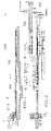
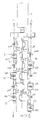
- Figures 1A and 2A show a schematic side view and Top view of a line with 4 feed sections in one Variant based on the first, starting from continuous casting to the end product using only horizontal intermediate rolling stands that alternate with Rotational means of the sections advanced by 90 ° between the individual rolling stands are arranged.
- Figure 3 shows a schematic view of the plant with only horizontal rolling stands alternating with Rotational means of the rolled products by 90 °.
- Fig. 4 shows a schematic view of the rolling phases with the variation parameters of the sections and increasing Speed increase of rolled products.
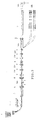
- Figures 5 and 5A show an enlarged view of the side elevation and the layout of the multi-wire continuous casting plant with two crucibles on a support tower, the allows the two crucibles to be used alternately, to get a continuous cast without interruptions.
- Fig. 5B shows the enlarged side elevation of the continuous casting plant.
- Fig. 5C and 5D show a floor plan and one of the cross section the continuous casting mold with four continuous casting sections.
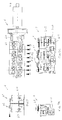
- Figures 6 and 6A show a side view and a floor plan the area of the rolling line in which the intermediate rolling group is located with horizontal and vertical roll stands, together with the variation and reduction scheme of the Section and increase in peripheral speed for each scaffold 6-7W.
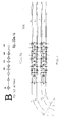
- Figures 7 and 7A show the floor plan of the multiple universal mill stand group with two wires at high speed WR and the corresponding variation diagram the sections at speeds between 12 m / sec. and 85 m / sec.
- Figures 7B, 7C and 7D each show the schematic Floor plan, cross section and transversal view a multi-wire universal rolling group that focuses on the refer to previous Figures 7 and 7A.
- Figures 8, 8A and 8B each show a side view, Front view and top view of a horizontal Roll stand from that shown in Figures 1 and 2 Investment.
- Figures 9, 9A, 9B and 9C each show the side view, Top view, the side cross section of the transmission system as well as the front view of a vertical Roll stand with two rows of staggered pairs of rollers according to Figures 1A and 2A.
- the HSD section is a post-treatment of the rolled product characterized.
- the WR section is called the "Wire Rod Line", i.e. Wire rolling line marked with final processing of the wire.
- a tunnel-shaped homogenization and / or thermal treatment furnace can e.g. temporarily also after the said Intermediate roll stands 6-7 may be provided.
- the flow form punch (10) has several aligned, each separate forming holes to directly one Variety of said strips to be rolled or leading To produce sections (b1, b2, b3, ... bn).
- Said flow die punch 10 is made of movable lever means 1001, 1002, 1003, 1004, 1005, 1006 with motor means 1007 supported.
- the curved line (b) of the flow punch 10 is visible; the punch has two separate cooling chambers c1, c2, in which water of different temperatures circulates (e1, e2). This solution serves for better control of the continuous casting parameters.
- the vertical multi-line mill has two rows of Rolling roller pairs 61, 62, where each line has a respective one Drive axle 610, 620 driven by a single M6 motor being, each pair of a cone gear too a roller wheel and from this by means of a cylinder gear second pair is driven.
- An alternative solution lies in the transmission of the rotation by means of a first one Roller pair line to the next second roller pair line (61 ' with 62 ', 62' with 62 ", 622 with 61 'etc.).
- the horizontal Roll stands 7 each have a pair of drive axles 710, 720, which are driven by a single motor M7 and each have an axis for each rolling line 71, 72.
- a thermal treatment can be carried out in one tunnel (TH) located on the line may be provided.
- a wire rod line (WRL) and a winding bearing (WM) may be provided.
- the final product (9) can obviously be in the form of coils (Wire on the side line) or bars (larger cross-sections on the line).
- a metal wire loop / rod (bs) is provided to compensation at different speeds during continuous casting upwards (101, 102, 10, 11.2 ... 5, ...) and during the rolling and the flow treatment downwards, To enable cutting and storage (TH, 8.9).
- the line WR of the wire is characterized by two lateral compact rolling blocks with two horizontal, parallel ones Rolling lines (L1, L2), characterized in that they three peripheral transmission waves (2, 3, 4) at the tips of an isosceles triangle, in which the two lower peripheral axes (3, 4) facing outwards inclined vertical scaffolding (VL, VR) and move the upper one peripheral axis horizontal, oppositely inclined Carries scaffolding (OL, OR) whose roles are identical at right angles with the two said rolling lines (L1, L2) are.
- Rolling block characterized in that it has the same number of vertical mill stands on the right (VR) and the left (VL) side on the two lower peripheral waves (3, 4) has, while 2xn roll stands on the upper shaft (2) half on the left (OL) and half are pressed on the right (R) side, all of them have the same structure.
- the said pentagon is advantageously isosceles; the number of formation holes is always greater than 1 and not limited to 4; the frameworks (3 iv, 7) are from reduced by approx. 60/70 mm to approx. 12 mm.
Landscapes
- Engineering & Computer Science (AREA)
- Mechanical Engineering (AREA)
- Metal Rolling (AREA)
- Meat, Egg Or Seafood Products (AREA)
- Processing Of Meat And Fish (AREA)
- Continuous Casting (AREA)
- Manufacturing And Processing Devices For Dough (AREA)
- Chemical And Physical Treatments For Wood And The Like (AREA)
Abstract
Description
- erste Walzmittel zum Walzen des besagten Stranggusses in Flachstäbe aus dem vorgeschobenen Material unter zunehmender Verminderung des Querschnitts;
- zweite Walzmittel mit gegenüberliegenden gerillten
Rollen zwecks Ausformung eines längs gerillten Flachstabes
beim Vorschub.
Diese Lösung sieht
- vor den besagten ersten Walzmitteln:
- einen Entzerrungsofen mit Induktionstunnel zur weiteren Erhitzung des vorgeschobenen Flachstabes aus den besagten Stranggussmitteln, um den Flachsstab auf Walztemperatur zu halten;
- eine seitliche Begrenzungswalzung mit vertikalen
Rollen, um den vorgeschobenen Flachstab auf einer
exakten, gleichbleibenden Breite zu halten;
- nach den besagten zweiten Walzmitteln sieht diese Lösung vor:
- Splittungsmittel zur Trennung in Längslinien zwecks Parallelwalzen einer Vielzahl von Streifen oder Stangen;
- Stangenrotationsmittel zur Rotation der besagten Vielzahl von Streifen um 90°;
- Zurichtungswalzmittel mir gegenüberliegenden gerillten Rollen zur fortlaufenden, parallelen Erzeugung von zugerichteten Stangen oder Drähten;
- die besagte Fließformstanze mindestens 4 gefluchtete, jeweils voneinander getrennte Formungslöcher besitzt, um direkt eine Anzahl "n" der zu walzenden Streifen/Stangen herzustellen, wobei "n" eine gerade Zahl ist: 4, 6, 8 ...;
- die besagte Fließformstanze des Stranggussmaterials mit einem Zugmittel mit Quetschrollen verbunden ist, um das besagte Stranggussmaterial durch die Fließformstanze hindurchzuzwingen, so dass dieses die Form einer Vielzahl von Würsten einnimmt, deren Form rund, oval oder vieleckig sein kann.;
- nach den besagten Quetschzugrollen ein tunnelförmiger Induktionsvorwärmofen vorgesehen ist;
- von einem Loop-Kontrollsystem der vorlaufenden Abschnitte gefolgt wird, die locker gehalten werden, um die Geschwindigkeitsvariationen zwischen den vor- und nachgeschalteten Abschnitten zu kompensieren;
- nach besagtem Kontrollsystem eine Reihe von Walzgerüsten folgen, die dazu bestimmt sind, den Querschnitt der Walzprodukte von 60-70 mm auf ca. 12 mm zu reduzieren, unter Zunahme der Periphergeschwindigkeit der Walzzylinder von 14 m/min am Einlauf auf ca. 12 m/sek. am Ausgang und
- nach den besagten Walzgerüsten ein Umführungssystem vorgesehen ist, das wie das vorhergehende ebenfalls mit einem Loop-Kontrollsystem ausgestattet für mindestens "n"/2 Universalwalzblöcke mit 12 Walzrollenpaargruppen ist, die in Form eines gleichschenkeligen Dreiecks gegenüberliegenden Paaren angeordnet sind zwecks Walzung von zwei parallelen und gegenüberliegenden Abschnitten/Drähten in drei Durchgängen mit einer peripheren Walzgeschwindigkeit der Rollen von ca. 85 m/sek.;
die Nummer 1 zur Kennzeichnung der Stranggussmittel dient;
die Nummer 10 die Fließformstanze der Stranggussmittel kennzeichnet (1);
die Nummer 11 die Stranggusslinie kennzeichnet;
die Nummer 2 die Zugmittel mit den Zug- und Vorschubrollen des Stranggussmaterials kennzeichnet;
die Nummer 3 die Not-Querschneidemittel kennzeichnet;
die Nummer 5 einen Nachheiztunnel mit Induktionsheizung kennzeichnet, in welchem das vorgeschobene Material auf Homogenisierungs- und Heißwalztemperatur gebracht wird;
die Nummern 6 und 6A das vertikale Walzgerüst mit mindestens zwei versetzt angeordneten, in n unterteilten Rollenpaarlinien kennzeichnen (n = Anzahl der Paare pro Linie) kennzeichnen;
die Nummern 7 und 7A ein horizontales Walzgerüst mit n Walzrillen kennzeichnen, die abwechslungsweise mit 90°-Rotationsmitteln des Walzerzeugnisses "iv" auftreten;
die Nummer 9 die Endzone und insbesondere die Aufwicklung des gewalzten Drahtes auf Spulen des Typs WM, WR und die Variante RR kennzeichnet;
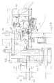
- einen einzelnen Motor (M) mit einer einzelnen Motorachse (1), die die Bewegung mittels eines Zahnradgetriebes (11) auf drei Zahnräder überträgt, die in Form eines gleichschenkeligen Dreiecks (21, 31, 41) radial angeordnet und jeweils mit peripheren Übertragungswellen (2, 3, 4) ausgestattet sind, auf welchen jeweils ein Walzgerüst (OR, VR, VL) angestiftet ist, wobei ein jedes Walzgerüst mit einem Paar Kopfwalzrollen (RR) versehen ist, welche die Rotationsübertragung mittels eines konischen Vorgeleges (c1) und die Zwischenübertragung (c2) von den besagten peripheren Übertragungswellen (2, 3, 4) empfangen.
- zwei der besagten peripheren Wellen sich als periphere Basiswellen (3, 4) auf der Höhe unterhalb der Basiswinkel des besagten gleichschenkeligen Dreiecks befinden und die dritte Welle sich als obere periphere Welle (2) an der oberen Spitze des besagten gleichschenkeligen Dreiecks befindet, wobei:
- die beiden peripheren Basiswellen (3, 4) die jeweiligen Walzgerüste auf der rechten und der linken Seite (VR, VL) mit den Walzrollenpaaren (RR) für vertikales Walzen nach rechts und nach links (VRR) nach oben bewegen;
- die besagte obere Welle (2) alternativ ein Gerüst nach rechts (OR) und ein Gerüst nach links (OL) mit dem entsprechenden Kopfrollenpaar (RR) für horizontales Walzen (ORR) unterstützt, wobei:
- die Positionierung der besagten peripheren Wellen (2, 3, 4), die Neigung und die Ausmaße der besagten Walzgerüste (OR, VL, VR) sowie die Position der entsprechenden Walzrollenpaare (RR) so ausgelegt ist, dass die jeweiligen Walzkanäle aller besagter Walzrollen (RR) auf zwei Längswalzlinien (L1, L2) zusammentreffen, die von einer Seite zur anderen symmetrisch, jeweils oberhalb der besagten peripheren Basiswellen (3, 4) und unterhalb sowie seitlich der besagten peripheren oberen Welle (2) verlaufen unter abwechselnder Anordnung von vertikalen Gerüsten und Walzrollen (VL/VR-VRR) und horizontalen Gerüsten und Walzrollen (OL/OR-ORR), wobei der Wechsel von einem horizontalen, rechten Walzgerüst (OR-ORR) bestimmt wird, das im Wechsel mit einem linken Walzgerüst (OL-ORR) agiert, wobei vorgesehen ist, dass auf der gegenüberliegenden Seite ein entsprechendes vertikales Walzgerüst, jeweils links (VL-VRR) und rechts (VR-VRR) in etwa auf derselben Höhe eintritt.
Claims (4)
- Strangguss- und Heißwalzanlage zur Parallel-Simultanfließerzeugung von einer Vielzahl von Stangen oder Drähten, welche Stranggussmittel (1) mit Fließformungsmitteln (10) zur fortlaufenden Lieferung auf mehreren Linien zur parallelen Herstellung einer Vielzahl von Streifen/Stangen/Drähten sowie Vertikal- und Horizontalzwalmittel zum fortlaufenden Heißwalzen derselben umfasst, dadurch gekennzeichnet, dass:die besagte Fließformstanze mindestens "n"=4 gefluchtete, jeweils voneinander getrennte Formungslöcher besitzt, um direkt eine Anzahl "n" der besagten, zu walzenden Streifen/Stangen herzustellen, wobei "n" eine gerade Zahl ist;die besagte Fließformstanze für Stranggussmaterial mit einem Zugmittel mit Quetschrollen verbunden ist, um das besagte Stranggussmaterial durch die Fließformstanze hindurchzuzwingen, so dass dieses die Form einer Vielzahl von Würsten einnimmt, deren Form rund, oval oder vieleckig sein kann;nach den besagten Quetschzugrollen (2-3) ein tunnelförmiger Induktionsvorwärmofen (5) vorgesehen ist; dervon einem Loop-Kontrollsystem der vorlaufenden Abschnitte gefolgt ist, die locker gehalten werden, um die Geschwindigkeitsvariationen zwischen den vor- und nachgeschalteten Abschnitten zu kompensieren;wobei nach besagtem Kontrollsystem eine Reihe von Walzgerüsten folgen, die dazu bestimmt sind, den Querschnitt der Walzprodukte von 60-70 mm auf ca. 12 mm zu reduzieren, unter Zunahme der Periphergeschwindigkeit der Walzzylinder von 14 m/min am Einlauf auf ca. 12 m/sek. am Ausgang undwobei nach den besagten Walzgerüsten ein Umführungssystem vorgesehen ist, das wie das vorhergehende ebenfalls mit einem Loop-Kontrollsystem ausgestattet ist für mindestens "n"/2 Universalwalzblöcke (6-7W) mit 12 Walzrollenpaargruppen (VL-VR), die in Form eines gleichschenkeligen Dreiecks (02, 03, 04) gegenüberliegenden Paaren angeordnet sind zwecks Walzung von zwei parallelen und gegenüberliegenden Abschnitten/Drähten in drei Durchgängen mit einer peripheren Walzgeschwindigkeit der Rollen von ca. 85 m/sek. (L1-L2) zu walzen;
- Strangguss- und Heißwalzanlage gemäß Anspruch 1, dadurch gekennzeichnet, dass die besagten Walzgerüste ausschließlich 6 horizontale Walzrollen besitzen, die sich mit den Rotationsmitteln des um 90° (iv) vorlaufenden Abschnitts abwechseln.
- Strangguss- und Heißwalzanlage gemäß Anspruch 1, dadurch gekennzeichnet, dass die besagten Walzgerüste sowohl horizontal (7) als auch vertikal (8) sind, wobei die vertikalen Walzgerüste die Anzahl der vertikalen Walzrollenpaare "n" umfassen, die auf zwei parallele, nebeneinanderliegende Reihen unterteilt sind mit einem Walzkanal, der um den halben Achsabstand versetzt angeordnet ist, wobei jede Reihe "n"/2 vertikale Walzrollenpaare umfasst, damit abwechslungsweise ein Abschnitt vom Walzrollenpaar der ersten Reihe und der angrenzende Abschnitt vom Walzrollenpaar der zweiten Reihe gewalzt wird.
- Anlage gemäß Anspruch 1, dadurch gekennzeichnet, dass jeder Walzblock mit zwei horizontalen Parallelwalzreihen (6 - 7W) drei periphere Übertragungswellen eines gleichschenkeligen Dreiecks (02, 03, 04) umfasst, wobei die beiden unteren peripheren Achsen (03, 04) das vertikale Rollenpaar (VR-VRR) antreiben, deren Achse nach außen geneigt sind (VL), während die obere periphere Achse (02) Walzrollenpaare trägt (OR-RR), die rechtwinklig deckungsgleich mit den beiden besagten Walzlinien (L1, L2) liegen.
Applications Claiming Priority (3)
| Application Number | Priority Date | Filing Date | Title |
|---|---|---|---|
| ITUD20010098 | 2001-05-25 | ||
| IT2001UD000098A ITUD20010098A1 (it) | 2001-05-25 | 2001-05-25 | Impianto perfezionato di colata continua e laminazione a caldo per la produzione in parallelo diversificata di barre o fili |
| ITPN010098 | 2001-05-25 |
Publications (2)
| Publication Number | Publication Date |
|---|---|
| EP1262248A1 true EP1262248A1 (de) | 2002-12-04 |
| EP1262248B1 EP1262248B1 (de) | 2004-12-01 |
Family
ID=11460592
Family Applications (1)
| Application Number | Title | Priority Date | Filing Date |
|---|---|---|---|
| EP02001550A Expired - Lifetime EP1262248B1 (de) | 2001-05-25 | 2002-01-23 | Verbesserte Strangguss- und Heisswalzanlage zur Parallelerzeugung von unterschiedlichen Stangen oder Drähten |
Country Status (6)
| Country | Link |
|---|---|
| US (1) | US6763561B2 (de) |
| EP (1) | EP1262248B1 (de) |
| JP (1) | JP2003010904A (de) |
| AT (1) | ATE283736T1 (de) |
| DE (1) | DE50201653D1 (de) |
| IT (1) | ITUD20010098A1 (de) |
Cited By (2)
| Publication number | Priority date | Publication date | Assignee | Title |
|---|---|---|---|---|
| ITTV20110131A1 (it) * | 2011-09-29 | 2013-03-30 | Pert S R L Con Unico Socio | Macchina per la laminazione a caldo di vergelle ed affini |
| ITVI20120122A1 (it) * | 2012-05-23 | 2013-11-24 | Invimec Srl | Laminatoio perfezionato |
Families Citing this family (11)
| Publication number | Priority date | Publication date | Assignee | Title |
|---|---|---|---|---|
| ITPN20010011A1 (it) * | 2001-02-15 | 2002-08-16 | Sms Demag Aktiengesellshaft | Impianto perfezionato di colata continua e laminazione a caldo per laproduzione in parallelo simultanea di barre o fili. |
| US7192551B2 (en) * | 2002-07-25 | 2007-03-20 | Philip Morris Usa Inc. | Inductive heating process control of continuous cast metallic sheets |
| US7191628B2 (en) * | 2004-07-29 | 2007-03-20 | Morgan Construction Company | Method of continuously hot rolling a heated billet into a plurality of finished products |
| ITMI20050315A1 (it) † | 2005-03-02 | 2006-09-03 | Danieli Off Mecc | Impianto compatto di produzione in continuo di barre e-o profili |
| US7191629B1 (en) | 2006-04-13 | 2007-03-20 | Morgan Construction Company | Modular rolling mill |
| IT1400496B1 (it) * | 2010-06-09 | 2013-06-11 | Danieli Off Mecc | Apparato e processo di laminazione vergella ad alta velocità. |
| ITVI20110074A1 (it) * | 2011-04-01 | 2012-10-02 | Sms Meer Spa | Apparato per la lavorazione dell'acciaio ad alto risparmio energetico e metodo relativo |
| ES2628833T3 (es) * | 2011-08-01 | 2017-08-04 | Primetals Technologies Germany Gmbh | Método y aparato para una laminación continua |
| GB2531073A (en) * | 2014-10-10 | 2016-04-13 | Teng Pong David | Method and apparatus for producing steel intermediate products |
| CN105170647A (zh) * | 2015-08-07 | 2015-12-23 | 辽宁科技大学 | 一种金属板带材连续成卷横纵轧制的方法 |
| CN109487100B (zh) * | 2018-11-29 | 2020-01-17 | 长江师范学院 | 一种导电铝合金杆连铸连轧及硼化处理方法及装置 |
Citations (2)
| Publication number | Priority date | Publication date | Assignee | Title |
|---|---|---|---|---|
| DD206087A1 (de) * | 1982-07-19 | 1984-01-18 | Reinhard Panning | Verfahren und einrichtung zur herstellung von feinstahl |
| US5404931A (en) * | 1990-02-15 | 1995-04-11 | Nippon Steel Corporation | Apparatus for making strips, bars and wire rods |
Family Cites Families (9)
| Publication number | Priority date | Publication date | Assignee | Title |
|---|---|---|---|---|
| US4129023A (en) * | 1977-10-11 | 1978-12-12 | Morgan Construction Company | Rolling mill |
| JPS57193205A (en) * | 1981-05-26 | 1982-11-27 | Sumitomo Metal Ind Ltd | Rolling method for steel bar or the like |
| DE4009861C2 (de) * | 1990-03-28 | 2003-06-12 | Sms Demag Ag | Verfahren zur Herstellung von warmgewalztem Stangenmaterial wie Feinstahl oder Draht und Anlage zur Durchführung des Verfahrens |
| NL9100911A (nl) * | 1991-03-22 | 1992-10-16 | Hoogovens Groep Bv | Inrichting en werkwijze voor het vervaardigen van warmgewalst staal. |
| IT1288842B1 (it) * | 1996-01-26 | 1998-09-25 | Simac Spa | Metodo e rispettivo impianto di laminazione a caldo per la produzione in continuo di barre, tondini o filo |
| NL1007730C2 (nl) * | 1997-12-08 | 1999-06-09 | Hoogovens Staal Bv | Inrichting en werkwijze voor het vervaardigen van een stalen band. |
| ITPN20010012A1 (it) * | 2001-02-15 | 2002-08-16 | Sms Demag Aktiengesellshaft | Blocco compatto di laminazione per due linee parallele. |
| ITPN20010010A1 (it) * | 2001-02-15 | 2002-08-16 | Sms Demag Aktiengesellshaft | Gabbia di laminazione verticale per impianto di laminazione a caldo per la produzione in parallelo simultanea di barre o fili. |
| ITPN20010011A1 (it) * | 2001-02-15 | 2002-08-16 | Sms Demag Aktiengesellshaft | Impianto perfezionato di colata continua e laminazione a caldo per laproduzione in parallelo simultanea di barre o fili. |
-
2001
- 2001-05-25 IT IT2001UD000098A patent/ITUD20010098A1/it unknown
-
2002
- 2002-01-23 AT AT02001550T patent/ATE283736T1/de not_active IP Right Cessation
- 2002-01-23 EP EP02001550A patent/EP1262248B1/de not_active Expired - Lifetime
- 2002-01-23 DE DE50201653T patent/DE50201653D1/de not_active Expired - Fee Related
- 2002-05-14 JP JP2002138519A patent/JP2003010904A/ja active Pending
- 2002-05-20 US US10/151,686 patent/US6763561B2/en not_active Expired - Fee Related
Patent Citations (2)
| Publication number | Priority date | Publication date | Assignee | Title |
|---|---|---|---|---|
| DD206087A1 (de) * | 1982-07-19 | 1984-01-18 | Reinhard Panning | Verfahren und einrichtung zur herstellung von feinstahl |
| US5404931A (en) * | 1990-02-15 | 1995-04-11 | Nippon Steel Corporation | Apparatus for making strips, bars and wire rods |
Cited By (4)
| Publication number | Priority date | Publication date | Assignee | Title |
|---|---|---|---|---|
| ITTV20110131A1 (it) * | 2011-09-29 | 2013-03-30 | Pert S R L Con Unico Socio | Macchina per la laminazione a caldo di vergelle ed affini |
| WO2013046178A1 (en) * | 2011-09-29 | 2013-04-04 | Pert S.R.L. Con Unico Socio | Wire-rod and the like hot-rolling machine |
| CN103974786A (zh) * | 2011-09-29 | 2014-08-06 | 佩特有限公司 | 线材及类似材料的热轧机 |
| ITVI20120122A1 (it) * | 2012-05-23 | 2013-11-24 | Invimec Srl | Laminatoio perfezionato |
Also Published As
| Publication number | Publication date |
|---|---|
| US6763561B2 (en) | 2004-07-20 |
| DE50201653D1 (de) | 2005-01-05 |
| US20020189075A1 (en) | 2002-12-19 |
| JP2003010904A (ja) | 2003-01-15 |
| ITUD20010098A1 (it) | 2002-11-25 |
| EP1262248B1 (de) | 2004-12-01 |
| ATE283736T1 (de) | 2004-12-15 |
Similar Documents
| Publication | Publication Date | Title |
|---|---|---|
| EP1262248B1 (de) | Verbesserte Strangguss- und Heisswalzanlage zur Parallelerzeugung von unterschiedlichen Stangen oder Drähten | |
| DE4402402A1 (de) | Verfahren und Anlage zur Herstellung von warmgewalztem Stahlband aus stranggegossenem Vormaterial | |
| DD262602A5 (de) | Verfahren und anlage zur herstellung von warmgewalztem stahlband | |
| EP1236522A2 (de) | Vertikales Walzgerüst für Heisswalzanlagen zur Parallel-Simultanerzeugung von Stangen oder Drähten | |
| AT406644B (de) | Präzisionswalzverfahren | |
| DE60001999T2 (de) | Längsteilvorrichtung zur Herstellung von mehreren Profilen | |
| DE1808822B2 (de) | Kontinuierliche mehradrige walzenstrasse zur herstellung von stabfoermigem walzgut, insbesondere von draht in grossen bundgewichten | |
| DE2437684C2 (de) | Walzwerk zur Herstellung von Draht und Rippenstahl | |
| DE2949970C2 (de) | Anlage zum Walzen von nahtlosen Metallrohren | |
| EP1463591B1 (de) | Verfahren und walzanlage zum herstellen von draht, stäben oder nahtlosen rohren | |
| EP1240954A2 (de) | Verbesserte Strangguss- und Heisswalzanlage zur Parallel-Simultanerzeugung von Stangen oder Drähten | |
| DE3039101A1 (de) | Anordnung einer kontinuierlich arbeitenden feinstahl-drahtwalzstrasse zum auswalzen von draht oder rundquerschnitten aus edelstaehlen oder hochwertigen legierungen | |
| DE3222930A1 (de) | Verfahren zur herstellung eines traegerrohlings fuer universaltraeger | |
| DE2042020A1 (de) | Verfahren zum kontinuierlichen Warmwalzen von Metallen | |
| EP3256276B1 (de) | Giessanlage | |
| DE202010018534U1 (de) | Giess- und kontinuierliche Walzanlage zur Herstellung von langen metallischen Walzerzeugnissen | |
| DE2705397C2 (de) | Verfahren zum Herstellen gleichzeitig mehrerer Stangen oder Stäbe aus einem Metallknüppel | |
| DE3317635A1 (de) | Warmwalzverfahren | |
| EP0560115A1 (de) | Verfahren und Walzwerk zum Präzisionswalzen von Draht bzw. von Walzgut mit Rundquerschnitt | |
| DE2529405A1 (de) | Verfahren zum profilwalzen | |
| EP1238719A2 (de) | Kompaktwalzblock für zwei parallele Linien | |
| EP0870554B1 (de) | Walzenstrasse zum Walzen von Flachstahl | |
| DE1010937B (de) | Verfahren und Vorrichtung zum Warmwalzen eines metallischen, halbflachen Werkstueckes in eine Stange mit trapezfoermigem Querschnitt | |
| DE2423751C3 (de) | Walzgerüst mit an den Pendelarmen drehbar gelagerten, intermittierend und gleichzeitig von entgegengesetzten Seiten auf das Walzgut einwirkenden Arbeitswalzen | |
| DE3411734A1 (de) | Vorrichtung zum strang-giesswalzen von metallen, insbesondere von stahl |
Legal Events
| Date | Code | Title | Description |
|---|---|---|---|
| PUAI | Public reference made under article 153(3) epc to a published international application that has entered the european phase |
Free format text: ORIGINAL CODE: 0009012 |
|
| AK | Designated contracting states |
Kind code of ref document: A1 Designated state(s): AT BE CH CY DE DK ES FI FR GB GR IE IT LI LU MC NL PT SE TR |
|
| AX | Request for extension of the european patent |
Free format text: AL;LT;LV;MK;RO;SI |
|
| 17P | Request for examination filed |
Effective date: 20030513 |
|
| AKX | Designation fees paid |
Designated state(s): AT BE CH CY DE DK ES FI FR GB GR IE IT LI LU MC NL PT SE TR |
|
| 17Q | First examination report despatched |
Effective date: 20031107 |
|
| GRAP | Despatch of communication of intention to grant a patent |
Free format text: ORIGINAL CODE: EPIDOSNIGR1 |
|
| GRAS | Grant fee paid |
Free format text: ORIGINAL CODE: EPIDOSNIGR3 |
|
| GRAA | (expected) grant |
Free format text: ORIGINAL CODE: 0009210 |
|
| AK | Designated contracting states |
Kind code of ref document: B1 Designated state(s): AT BE CH CY DE DK ES FI FR GB GR IE IT LI LU MC NL PT SE TR |
|
| PG25 | Lapsed in a contracting state [announced via postgrant information from national office to epo] |
Ref country code: TR Free format text: LAPSE BECAUSE OF FAILURE TO SUBMIT A TRANSLATION OF THE DESCRIPTION OR TO PAY THE FEE WITHIN THE PRESCRIBED TIME-LIMIT Effective date: 20041201 Ref country code: IE Free format text: LAPSE BECAUSE OF FAILURE TO SUBMIT A TRANSLATION OF THE DESCRIPTION OR TO PAY THE FEE WITHIN THE PRESCRIBED TIME-LIMIT Effective date: 20041201 Ref country code: NL Free format text: LAPSE BECAUSE OF FAILURE TO SUBMIT A TRANSLATION OF THE DESCRIPTION OR TO PAY THE FEE WITHIN THE PRESCRIBED TIME-LIMIT Effective date: 20041201 Ref country code: FR Free format text: LAPSE BECAUSE OF NON-PAYMENT OF DUE FEES Effective date: 20041201 Ref country code: FI Free format text: LAPSE BECAUSE OF FAILURE TO SUBMIT A TRANSLATION OF THE DESCRIPTION OR TO PAY THE FEE WITHIN THE PRESCRIBED TIME-LIMIT Effective date: 20041201 |
|
| REG | Reference to a national code |
Ref country code: GB Ref legal event code: FG4D Free format text: NOT ENGLISH |
|
| REG | Reference to a national code |
Ref country code: CH Ref legal event code: EP |
|
| REG | Reference to a national code |
Ref country code: IE Ref legal event code: FG4D Free format text: GERMAN |
|
| REF | Corresponds to: |
Ref document number: 50201653 Country of ref document: DE Date of ref document: 20050105 Kind code of ref document: P |
|
| REG | Reference to a national code |
Ref country code: SE Ref legal event code: TRGR |
|
| PG25 | Lapsed in a contracting state [announced via postgrant information from national office to epo] |
Ref country code: LU Free format text: LAPSE BECAUSE OF NON-PAYMENT OF DUE FEES Effective date: 20050123 Ref country code: CY Free format text: LAPSE BECAUSE OF FAILURE TO SUBMIT A TRANSLATION OF THE DESCRIPTION OR TO PAY THE FEE WITHIN THE PRESCRIBED TIME-LIMIT Effective date: 20050123 |
|
| PG25 | Lapsed in a contracting state [announced via postgrant information from national office to epo] |
Ref country code: BE Free format text: LAPSE BECAUSE OF NON-PAYMENT OF DUE FEES Effective date: 20050131 Ref country code: MC Free format text: LAPSE BECAUSE OF NON-PAYMENT OF DUE FEES Effective date: 20050131 |
|
| PG25 | Lapsed in a contracting state [announced via postgrant information from national office to epo] |
Ref country code: GR Free format text: LAPSE BECAUSE OF FAILURE TO SUBMIT A TRANSLATION OF THE DESCRIPTION OR TO PAY THE FEE WITHIN THE PRESCRIBED TIME-LIMIT Effective date: 20050301 Ref country code: DK Free format text: LAPSE BECAUSE OF FAILURE TO SUBMIT A TRANSLATION OF THE DESCRIPTION OR TO PAY THE FEE WITHIN THE PRESCRIBED TIME-LIMIT Effective date: 20050301 |
|
| PG25 | Lapsed in a contracting state [announced via postgrant information from national office to epo] |
Ref country code: ES Free format text: LAPSE BECAUSE OF FAILURE TO SUBMIT A TRANSLATION OF THE DESCRIPTION OR TO PAY THE FEE WITHIN THE PRESCRIBED TIME-LIMIT Effective date: 20050312 |
|
| GBT | Gb: translation of ep patent filed (gb section 77(6)(a)/1977) |
Effective date: 20050320 |
|
| NLV1 | Nl: lapsed or annulled due to failure to fulfill the requirements of art. 29p and 29m of the patents act | ||
| REG | Reference to a national code |
Ref country code: IE Ref legal event code: FD4D |
|
| BERE | Be: lapsed |
Owner name: SMS DEMAG AG Effective date: 20050131 |
|
| PLBE | No opposition filed within time limit |
Free format text: ORIGINAL CODE: 0009261 |
|
| STAA | Information on the status of an ep patent application or granted ep patent |
Free format text: STATUS: NO OPPOSITION FILED WITHIN TIME LIMIT |
|
| 26N | No opposition filed |
Effective date: 20050902 |
|
| PGFP | Annual fee paid to national office [announced via postgrant information from national office to epo] |
Ref country code: DE Payment date: 20060112 Year of fee payment: 5 Ref country code: SE Payment date: 20060112 Year of fee payment: 5 |
|
| PGFP | Annual fee paid to national office [announced via postgrant information from national office to epo] |
Ref country code: AT Payment date: 20060113 Year of fee payment: 5 |
|
| PGFP | Annual fee paid to national office [announced via postgrant information from national office to epo] |
Ref country code: GB Payment date: 20060120 Year of fee payment: 5 |
|
| EN | Fr: translation not filed | ||
| PG25 | Lapsed in a contracting state [announced via postgrant information from national office to epo] |
Ref country code: LI Free format text: LAPSE BECAUSE OF NON-PAYMENT OF DUE FEES Effective date: 20060131 Ref country code: CH Free format text: LAPSE BECAUSE OF NON-PAYMENT OF DUE FEES Effective date: 20060131 |
|
| PGFP | Annual fee paid to national office [announced via postgrant information from national office to epo] |
Ref country code: IT Payment date: 20060131 Year of fee payment: 5 |
|
| REG | Reference to a national code |
Ref country code: CH Ref legal event code: PL |
|
| PG25 | Lapsed in a contracting state [announced via postgrant information from national office to epo] |
Ref country code: SE Free format text: LAPSE BECAUSE OF NON-PAYMENT OF DUE FEES Effective date: 20070124 |
|
| PG25 | Lapsed in a contracting state [announced via postgrant information from national office to epo] |
Ref country code: DE Free format text: LAPSE BECAUSE OF NON-PAYMENT OF DUE FEES Effective date: 20070801 |
|
| EUG | Se: european patent has lapsed | ||
| GBPC | Gb: european patent ceased through non-payment of renewal fee |
Effective date: 20070123 |
|
| PG25 | Lapsed in a contracting state [announced via postgrant information from national office to epo] |
Ref country code: GB Free format text: LAPSE BECAUSE OF NON-PAYMENT OF DUE FEES Effective date: 20070123 Ref country code: AT Free format text: LAPSE BECAUSE OF NON-PAYMENT OF DUE FEES Effective date: 20070123 |
|
| BERE | Be: lapsed |
Owner name: *SMS DEMAG A.G. Effective date: 20050131 |
|
| PG25 | Lapsed in a contracting state [announced via postgrant information from national office to epo] |
Ref country code: PT Free format text: LAPSE BECAUSE OF NON-PAYMENT OF DUE FEES Effective date: 20050501 |
|
| PG25 | Lapsed in a contracting state [announced via postgrant information from national office to epo] |
Ref country code: IT Free format text: LAPSE BECAUSE OF NON-PAYMENT OF DUE FEES Effective date: 20070123 |