EP1256397B1 - Procédé d'hydroformage de feuilles métalliques et appareil - Google Patents
Procédé d'hydroformage de feuilles métalliques et appareil Download PDFInfo
- Publication number
- EP1256397B1 EP1256397B1 EP02291140A EP02291140A EP1256397B1 EP 1256397 B1 EP1256397 B1 EP 1256397B1 EP 02291140 A EP02291140 A EP 02291140A EP 02291140 A EP02291140 A EP 02291140A EP 1256397 B1 EP1256397 B1 EP 1256397B1
- Authority
- EP
- European Patent Office
- Prior art keywords
- hole
- die
- fluid
- blank
- thru
- Prior art date
- Legal status (The legal status is an assumption and is not a legal conclusion. Google has not performed a legal analysis and makes no representation as to the accuracy of the status listed.)
- Expired - Lifetime
Links
Images


Classifications
-
- B—PERFORMING OPERATIONS; TRANSPORTING
- B21—MECHANICAL METAL-WORKING WITHOUT ESSENTIALLY REMOVING MATERIAL; PUNCHING METAL
- B21D—WORKING OR PROCESSING OF SHEET METAL OR METAL TUBES, RODS OR PROFILES WITHOUT ESSENTIALLY REMOVING MATERIAL; PUNCHING METAL
- B21D26/00—Shaping without cutting otherwise than using rigid devices or tools or yieldable or resilient pads, i.e. applying fluid pressure or magnetic forces
- B21D26/02—Shaping without cutting otherwise than using rigid devices or tools or yieldable or resilient pads, i.e. applying fluid pressure or magnetic forces by applying fluid pressure
- B21D26/021—Deforming sheet bodies
- B21D26/023—Deforming sheet bodies including an additional treatment performed by fluid pressure, e.g. perforating
-
- B—PERFORMING OPERATIONS; TRANSPORTING
- B21—MECHANICAL METAL-WORKING WITHOUT ESSENTIALLY REMOVING MATERIAL; PUNCHING METAL
- B21D—WORKING OR PROCESSING OF SHEET METAL OR METAL TUBES, RODS OR PROFILES WITHOUT ESSENTIALLY REMOVING MATERIAL; PUNCHING METAL
- B21D26/00—Shaping without cutting otherwise than using rigid devices or tools or yieldable or resilient pads, i.e. applying fluid pressure or magnetic forces
- B21D26/02—Shaping without cutting otherwise than using rigid devices or tools or yieldable or resilient pads, i.e. applying fluid pressure or magnetic forces by applying fluid pressure
- B21D26/053—Shaping without cutting otherwise than using rigid devices or tools or yieldable or resilient pads, i.e. applying fluid pressure or magnetic forces by applying fluid pressure characterised by the material of the blanks
- B21D26/059—Layered blanks
-
- Y—GENERAL TAGGING OF NEW TECHNOLOGICAL DEVELOPMENTS; GENERAL TAGGING OF CROSS-SECTIONAL TECHNOLOGIES SPANNING OVER SEVERAL SECTIONS OF THE IPC; TECHNICAL SUBJECTS COVERED BY FORMER USPC CROSS-REFERENCE ART COLLECTIONS [XRACs] AND DIGESTS
- Y10—TECHNICAL SUBJECTS COVERED BY FORMER USPC
- Y10T—TECHNICAL SUBJECTS COVERED BY FORMER US CLASSIFICATION
- Y10T29/00—Metal working
- Y10T29/49—Method of mechanical manufacture
- Y10T29/4935—Heat exchanger or boiler making
- Y10T29/49373—Tube joint and tube plate structure
- Y10T29/49375—Tube joint and tube plate structure including conduit expansion or inflation
-
- Y—GENERAL TAGGING OF NEW TECHNOLOGICAL DEVELOPMENTS; GENERAL TAGGING OF CROSS-SECTIONAL TECHNOLOGIES SPANNING OVER SEVERAL SECTIONS OF THE IPC; TECHNICAL SUBJECTS COVERED BY FORMER USPC CROSS-REFERENCE ART COLLECTIONS [XRACs] AND DIGESTS
- Y10—TECHNICAL SUBJECTS COVERED BY FORMER USPC
- Y10T—TECHNICAL SUBJECTS COVERED BY FORMER US CLASSIFICATION
- Y10T29/00—Metal working
- Y10T29/49—Method of mechanical manufacture
- Y10T29/49805—Shaping by direct application of fluent pressure
-
- Y—GENERAL TAGGING OF NEW TECHNOLOGICAL DEVELOPMENTS; GENERAL TAGGING OF CROSS-SECTIONAL TECHNOLOGIES SPANNING OVER SEVERAL SECTIONS OF THE IPC; TECHNICAL SUBJECTS COVERED BY FORMER USPC CROSS-REFERENCE ART COLLECTIONS [XRACs] AND DIGESTS
- Y10—TECHNICAL SUBJECTS COVERED BY FORMER USPC
- Y10T—TECHNICAL SUBJECTS COVERED BY FORMER US CLASSIFICATION
- Y10T29/00—Metal working
- Y10T29/49—Method of mechanical manufacture
- Y10T29/49826—Assembling or joining
- Y10T29/49893—Peripheral joining of opposed mirror image parts to form a hollow body
-
- Y—GENERAL TAGGING OF NEW TECHNOLOGICAL DEVELOPMENTS; GENERAL TAGGING OF CROSS-SECTIONAL TECHNOLOGIES SPANNING OVER SEVERAL SECTIONS OF THE IPC; TECHNICAL SUBJECTS COVERED BY FORMER USPC CROSS-REFERENCE ART COLLECTIONS [XRACs] AND DIGESTS
- Y10—TECHNICAL SUBJECTS COVERED BY FORMER USPC
- Y10T—TECHNICAL SUBJECTS COVERED BY FORMER US CLASSIFICATION
- Y10T29/00—Metal working
- Y10T29/49—Method of mechanical manufacture
- Y10T29/49826—Assembling or joining
- Y10T29/49908—Joining by deforming
- Y10T29/49938—Radially expanding part in cavity, aperture, or hollow body
- Y10T29/49941—Peripheral edge joining of abutting plates
Definitions
- the present invention relates to a metallic sheet hydroforming method using metallic sheets as blanks, as well as a forming die used in the method.
- a sheet hydroforming method is known in which peripheral portions of two metallic sheets (hereinafter referred to also as “blanks”) are bonded together, then a fluid is introduced between the blanks, followed by the application of pressure of the fluid, causing the blanks to be bulged.
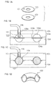
- FIGS. 1A, 1B, 1C, and 1D illustrate a forming method described in Japanese Patent Application Laid Open No. 47-033864.
- FIG. 1A is a perspective view of two blanks which are each in a ring shape
- FIG. 1B is a sectional view of a die portion before a forming work in which two blanks bonded together at their peripheral portions are set between upper and lower dies
- FIG. 1C is a sectional view of the die portion in a completed state of sheet hydroforming
- FIG. 1D is a perspective view of a bent tubular part obtained by cutting a formed part on workpiece crosswise.
- the blanks shown in FIG. 1A are in a state before being subjected to peripheral bonding into a single blank.
- the blanks are two ring-like blanks 100 and 102.
- a pipe-like nozzle 101 is bonded, for example by welding, to the position of a thru-hole formed in a planar portion of the blank 100.
- the blanks 100 and 102 are put one on the other and are bonded together for example by welding throughout the whole inner and outer peripheries thereof to afford a workpiece ("bonded blank" hereinafter).
- the bonded blank, indicated at 103 is set on a lower die 104, then an upper die 105 is brought down from above by means of a drive unit (not shown), an outer peripheral portion 103a and an inner peripheral portion 103b of the bonded blank are pressed and sandwiched in between the upper and lower dies, and the nozzle and a pipe 106 are connected together through a thru-hole 105b formed in the upper die.
- Die cavities 104a and 105a having an inner contour shape which is the same as an outer contour shape of product are formed in the lower die 104 and upper die 105, respectively.
- a fluid is introduced between mating surfaces of the bonded blank from a pump (not shown) through the pipe and nozzle, followed by the application of pressure, causing the bonded blank to bulge.
- the full-circled bonding of the blanks 100 and 102 is for the purpose of preventing the leakage of fluid from the mating surfaces of the bonded blank.
- the first advantage is that the bonding is easy because the blanks are bonded in a flat state.
- it is necessary to use a jig for shape correction and alignment with respect to each of elastically recovered stamped parts, and the number of working steps increases.
- the second advantage is that since the working is done using upper and lower dies and fluid, the tool expenses are low in comparison with the press stamping method.
- the third advantage is that since a stretch formed portion is created by forming with a tensile stress based on a fluid pressure, a problem such as body wrinkling, which is often observed in press stamping, is difficult to occur.
- FIGS. 2A and 2B are diagrams for explaining a forming method disclosed in Japanese Patent Application Laid Open No. 63-295029.
- FIG. 2A is a perspective view of a bonded blank before forming and
- FIG. 2B is a perspective view of a formed part on workpiece.
- two blanks 110 and 111 which are fabricated in a developed shape of a desired product by a press punching method for example, are put one on the other and outer peripheral edges 112 of their mating surfaces are bonded together by a laser welding method for example to afford a bonded blank 113.
- the bonded blank 113 is then set within upper and lower dies and pressurized fluid is introduced between the mating surfaces from a suitable bonded blank opening, causing the blank to bulge.
- the resulting formed part is an engine manifold part 117 having a welded line 116, in which manifold portions 114 and a trunk portion 115 are cut at their end portions.
- FIGS. 3A, 3B, 3C, 3D, and 3E are diagrams explanatory of a forming method disclosed in Japanese Patent Application Laid Open No. 09-029329.
- FIG. 3A shows blanks 120 and 121 before bonding, the blanks 120 and 121 being formed with half conical recesses 120a and 121a on flange, respectively, by press stamping.
- FIG. 3B shows a bonded blank 123 obtained by superimposing blanks 120 and 121 one on the other and bonding the two by, say, laser welding along a continuous welded line 123b except a conical inlet 123a.
- FIG. 3A shows blanks 120 and 121 before bonding, the blanks 120 and 121 being formed with half conical recesses 120a and 121a on flange, respectively, by press stamping.
- FIG. 3B shows a bonded blank 123 obtained by superimposing blanks 120 and 121 one on the other and bonding the two by, say, laser welding along a continuous welded
- 3C shows a state in which a peripheral portion of the bonded blank 123 is held grippingly by lower die 125 and upper die 126 attached to a press machine (not shown), then a conical head 127b of an injection nozzle 127 is inserted into the inlet 123 by means of a drive unit (not shown) and is pushed against half conical recesses 125b and 126b on die surfaces. Then, pressurized fluid is injected between the blank mating surfaces from a pump (not shown) through an intra-nozzle channel 127a, causing die cavities 125a and 126a having the same inner contour shape as an outer contour shape of product to bulge.
- FIG. 3D shows a completely bulged state in which the blanks were brought into contact with inner walls of the die cavities 125a and 126a by increasing the pressure of fluid 128. Thereafter, the pressure of the fluid is decreased and the fluid is discharged from the inlet 123a to afford a formed part 129.
- FIG. 3E shows an example of a tubular part 129 obtained by cutting off the portion located outside the welded line 123b and also cutting off both ends of the stretch formed portion of workpiece.
- FIG. 4 is a front view showing the inlet 123a as seen in the direction of arrow A in FIG. 3B. Since bent portions 130 are rounded at a radius at least equal to the blank thickness, there are formed tapered grooves 131 and hence it is necessary to prevent the leakage of pressurized fluid from the grooves 131. But in Japanese Patent Application Laid Open No. 09-029329 there is found no explanation about a method to be taken for the prevention of such fluid leakage.
- US-A-4 331 284 discloses a method of using materials e.g. titanium or its alloys that exhibit superplastic properties as stacked work pieces, in a temperature range in which the super plastic properties are exhibited and the diffusion bonding is conducted.
- US-A-3 807 009 discloses a method of forming curved tube sections from a tube loop, comprising closing the tube loop along the longitudinal axis and cutting it along the plane traverse to the axis, thereby forming tube sections, the method comprising abutting two blanks made of material, from which the tube sections are to be formed, in a sandwich form and introducing a pressurized agent into the closed space defined between the blanks, so as to subject the material to plastic deformation and form a loop.
- FIGS. 8A, 8B, and 8C illustrate tools used in press stamping, a state of stamping, and an example of a formed part.
- FIG. 8A illustrates a state in which a blank 203 is set on a die 204 fixed to a press bed 211 and a peripheral portion 203b of the blank is binded against a die surface 204a at a predetermined load with use of a blank holder 205, the blank holder 205 being attached to outer slide 212 which has been moved down from above by means of a drive unit (not shown).
- the peripheral portion of the blank is clamped with concave and convex portions 208 ("beads" hereinafter) formed opposedly on both die surface 204a and blank holder surface 205b around a die cavity 204e.
- a punch 206 attached to inner slide 213 which has been brought down from above by another drive unit (not shown) is moved down through a space formed inside the blank holder.
- a tensile force acts on the blank because the peripheral portion of the blank is pressed by both die and blank holder.
- FIG. 8B shows a state in which the punch has descended to a bottom of the die cavity and a stretch formed portion (also referred to as "panel surface") 207a is formed between a punch surface 206a and a die bottom 204b. Thereafter, the punch and subsequently the blank holder are raised and a formed part 207 is taken out.
- a stretch formed portion also referred to as "panel surface”
- FIG. 8C illustrates the formed part.
- Bead patterns 207d formed by the beads 208 remain on a peripheral portion ("flange" hereinafter) 207b of the formed part. In steps which follow the flange is cut off to obtain the panel part 201.
- the first reason is that in case of the panel surface being a curved surface and if stretch deformation is extremely small, the product is prevented from having a predetermined radius of curvature due to an elastic recovery. In this case there also arises an inconvenience such that a elastic stiffness (difficulty of elastic deflection) of the panel surface is low and there occurs “canning" when a local load is applied to the panel surface.
- the second reason is that if an increase in yield stress ( ⁇ A') of the panel surface induced by stretch deformation is small, the foregoing dent resistance becomes insufficient.
- the material of the panel surface is in a biaxially stretched state under the action of a surrounding tensile force, and for increasing the amount of stretch deformation of the panel surface it is necessary to increase the tensile force acting on the panel surface during press forming.
- This tensile force is created by resistance ("drawing resistance” hereinafter) which is induced when the flange is pulled into the die cavity by the punch.
- the blank holder force is restricted by the capacity of the press machine used and the flange area is set to a minimum area from the standpoint of blank yield, so with these means it is difficult to ensure a required drawing resistance.
- the bead compensates for the deficiency in the drawing resistance.
- a drawing resistance is created by a bending deformation induced when the flange passes the bead.
- the bead is arranged at a position where the drawing resistance of the flange is small, such as a straight side portion of the die cavity contour, as shown in FIG. 8C.
- a friction occurs between the punch surface and a punch shoulder 206b and this frictional force suppresses the stretch deformation of the panel surface.
- the second factor is a bending at the punch shoulder.
- the present invention has been accomplished in view of the above-mentioned problems and it is an object of the invention to provide a sheet hydroforming method wherein a pressurized fluid can be injected between mating surfaces of two blanks easily and without leakage of the fluid, further provide a forming die used therein and a formed part on workpiece obtained by the method, as well as the above method able to improve dent resistance, a forming die used therein and a formed product obtained by the method.
- the two stacked metallic sheets are obtained by superimposing one metallic sheet on the other metallic sheet.
- FIGS. 9A and 9B are perspective views showing an example of blanks used in the hydroforming method of the present invention, of which FIG. 9A shows a blank 1 and FIG. 9B shows a blank 2 having a pierced hole for the injection of fluid in a predetermined position, the pierced hole being formed, for example, by punching or by a laser cutting method.
- the diameter, d, of the pierced hole 3 it will be described later.
- the pierced hole 3 may be provided in a plural number.
- blanks will hereinafter be described as two blanks 1 and 2, the present invention is also applicable to the case where one or both of the blanks 1 and 2 is (are) a laminate(s) of plural metallic sheets or a stacked composite(s) of a metallic sheet and a non-metallic sheet such as plastic.
- the present invention is further applicable even to the case where one or both of the blanks 1 and 2 is (are) a tailored blank(s) obtained by bonding edge portions or the vicinity thereof of plural metallic sheets of the same material and different thicknesses or plural metallic sheets of the same thickness and formed of different materials by a suitable boding method such as welding.
- FIGS. 10A, 10B, and 10C are perspective views showing different modes of double sheet blanks each comprising blanks 1 and 2 superimposed together and employable in the present invention.
- FIG. 10A shows a double sheet blank 4 of merely stacked blanks.
- the blanks may be bonded at several positions near their edge portions by spot welding for example.
- FIG. 10B shows a double sheet blank 5 obtained by superimposing the blanks 1 and 2 together and welding the two into an integral mass throughout the whole circumference by laser welding for example. As to the position of a welded line 5b, it will be described later.
- FIG. 10C shows an example of a double sheet blank 7 of a further different mode. Interfaces of the blanks 1 and 2 are integrally bonded in a hatched planar area ("bonded area” hereinafter) located outside a closed curve 7b ("inside contour line of bonded area” hereinafter) which is represented by a dash-double dot line, by bonding with adhesive or brazing.
- the hatched area represents a bonded area on mating surfaces of the blanks 1 and 2.
- a pierced hole on blank may be formed in a position inside the bonded area which position may be set in the same manner as is the case with the welded line 5b of the double sheet blank 5 in FIG. 10B.
- FIG. 11 is a sectional view of a die portion for explaining an example of the hydroforming method of the present invention using the double sheet blank 4.
- the same figure shows a state in which the double sheet blank 4 is set on a holding surface 11a of a lower die 11 fixed to a bed 20 of a press machine (not shown), a slide 21 of the press machine with an upper die 10 attached thereto is brought down with a drive unit (not shown), allowing a holding surface 10a of the upper die to come into contact with the double sheet blank, and the slide is pressed with a pressing device (not shown) to clamp a peripheral plane portion 4a ("flange" hereinafter) of the double sheet blank.
- 11 are respectively formed die cavities 10b and 11b having the same inner contour shape as an outer contour shape of product.
- a thru-hole 11d is formed for introducing a pressurized medium which thru-hole lead to the holding surface of the lower die.
- the lower die is sideways provided with a connector 14a so as to permit connection with and disconnection from piping 14.
- a channel-forming groove 10d is formed in the holding surface of the upper die in a position opposed to the thru-hole formed in the die so as to extend to the upper die cavity.
- a drain hole 11e is formed leading to piping 15 which is connected removably to the connector 15a.
- Air exhaust thru-holes 10c and 11c leading to the exterior of the die portion from the die cavities 10b and 11b are formed in the upper and lower dies respectively.
- the air exhaust thru-holes are formed, for example, in round corner portions 10i and 11i so that indentation thereof may not remain in the resulting formed part.
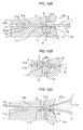
- FIGS. 12A, 12B, and 12C are enlarged diagrams of a portion C enclosed with a dotted line in FIG. 11, of which FIG. 12A is a diagram for explaining a fluid sealing method in an opening of the thru-hole 11d in the lower die which opening faces the holding surface of the die.
- FIG. 12A is a diagram for explaining a fluid sealing method in an opening of the thru-hole 11d in the lower die which opening faces the holding surface of the die.
- a circular groove 11f is formed in the holding surface 11a of the lower die so as to surround the thru-hole 11d.
- An O-ring 16 made of an elastic material such as rubber is fitted in the circular groove.
- An inside diameter (D) of the circular groove, as well as the width and depth of the same groove, may be determined in accordance with the inside diameter and thickness of the O-ring and on the basis of, for example, JIS B2406.
- the pierced hole 3 on blank is located at the same position as the thru-hole 11d and its diameter (d) is determined smaller than the inside diameter (D) of the circular groove.
- the holding surfaces of the upper and lower dies are formed with a bead 10g and a bead groove 11g respectively at a position outside the channel-forming groove 10d and thus a local concave-convex pattern ("bead pattern" hereinafter) 25e is formed on a flange 4a. Vertical positions of the bead and the bead groove may be reversed.
- the bead pattern is formed by clamping the double sheet blank with the upper and lower dies. As to the role of the bead pattern 25e, it will be described later.
- FIG. 12B is a sectional view as seen in an arrowed direction E-E in FIG. 12A.
- the width (w) of the fluid channel is set equal to or somewhat smaller than the inside diameter (D) of the circular groove.
- FIG. 12C shows this state, in which the blanks 1 and 2 are bulged within the upper and lower die cavities 10b, 11b with pressurized fluid 17 which has entered through the gap formed between both blanks.
- a double sheet blank having plural pierced holes 3, and the same number of such structures as indicated by arrow C in FIG. 11 may be provided at corresponding positions of the upper and lower dies.
- water emulsion with oil or fat for rust prevention is most suitable in point of cost.
- the air present within the upper and lower die cavities is discharged to the exterior gradually through the air exhaust thru-holes 10c and 11c.
- FIG. 13 illustrates a state in which a bulging deformation with fluid has been started in the forming step.
- the blanks 1 and 2 present within the die cavities bulge centrally in a dome shape.
- a stretch deformation of the blanks becomes the largest centrally of the dome-like bulged portion.
- the central bulging proceeds until the bulge top comes into contact with die cavity bottoms 10h and 11h. Thereafter, the area of contact with the die cavity bottoms becomes wider.
- the air present within the die cavities is discharged to the exterior gradually through the air exhaust thru-hole in the course of stretch formation.
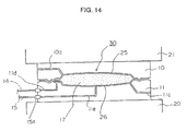
- FIG. 14 shows a completed state of blank bulging in the die cavities.
- a stretch formed part 30 composed of upper and lower formed parts 25, 26.
- the pressure of the pressurized medium is reduced, then the upper die is raised, the stretch formed part is lifted and taken out from the lower die, and medium is discharged from the pierced hole 3 on blank.
- the medium spilling into the lower die cavity is discharged from the drain hole 11e, then passes through a removable joint 15a and is returned for re-use into a tank (not shown) through piping. It goes without saying that if plural thru-holes for introducing pressurized medium are formed, the discharge of the medium can be done efficiently.
- a punching work may be done subsequent to the stretch forming work as shown, for example, in FIGS. 15A and 15B.
- a hydraulic cylinder 13 equipped with a piercing punch 12 is installed at a predetermined position within the die cavities, the blanks are allowed to contact the whole inner contour portions of the upper and lower die cavities, thereafter, while the pressurized medium is maintained at a predetermined pressure level, the hydraulic cylinder 13 is actuated to move the punch 12 forward to pierce a hole as shown in FIG. 15B for example.
- a partial roundness 12a is formed at a peripheral edge portion of the tip of the punch 12, it is possible to pierce a hole without separation of slug 51, thus eliminating the necessity of slug recovery.
- a separative punching which premises the recovery of slug may also be done.
- the pressure of the pressurized medium is reduced and the piercing punch is retracted.
- the resulting punched thru-hole on the lower side, indicated at 52 is also employable as a discharge hole for the medium. If such a punched thru-hole is formed also on the upper die side, it can be used as an air intake port at the time of discharging the medium, whereby the discharge of pressurized medium can be performed efficiently.
- FIGS 16A, 16B, and 16C are perspective views of formed parts, of which FIG. 16A shows a stretch formed part 30 just after the hydroforming.
- a protuberance 25b which corresponds to the channel forming groove 10d, is formed adjacent to a stretch formed portion 25a of workpiece.
- On the flange 4a is formed a bead pattern 25e in a closed curve shape. The reason for this will be stated later. Thereafter, the flange is cut off along the position of a closed curve 25c (also referred to as "trimming line” hereinafter) located inside the bead pattern by a known means such as the use of a trimming die or by laser trimming.
- FIGS. 16B and 16C illustrate panel parts 31 and 32 obtained by separation up and down after cutting off the flange. In the case where the double sheet blank is a mere stack of two blanks, the flange may be cut off after separation into the upper and lower formed parts 25, 26.
- FIGS. 17A and 17B are perspective views of stretch formed parts 30a and 30b corresponding to the double sheet blanks 5 and 7, respectively.
- a protuberance 25b corresponding to the channel-forming groove 10d is formed in adjacency to a stretch formed portion 25a, and outside the protuberance 25b is formed a partial bead pattern 25e.
- a welded line 5b1 on flange in FIG. 17A indicates in which position of the stretch formed part the welded line 5b of the double sheet blank 5 is located, while an inside contour line 7b1 of bonded area on the flange in FIG.
- 17B indicates in which position of the stretch formed part the inside contour line 7b of bonded area on the double sheet blank 7 is located.
- FIG. 18 is a sectional view showing an example of a flange cutting method for a stretch formed part 30a with use of a trimming die 300.
- the stretch formed part 30a is set on a lower die 300a, then while a flange 5a is clamped with a work holder 300c which is pressed with a spring 300d, an upper die 300b is brought down with a drive unit (not shown) to cut off the flange 5a.
- a drive unit not shown
- the position of the welded line 5b on blank in FIG. 10B lies between a contour 25d of the stretch formed portion of workpiece and the trimming line 25c.
- a planar shape of the inside contour line 7b of bonded area on the blank 7 is set so that the inside contour line 7b1 of bonded area remains between the periphery 25d of the stretch formed portion and the trimming line 25c.
- the bead pattern formed on the flange fulfills the following three functions.
- the first function is preventing pressurized medium from leaking to the exterior of the flange from the blank interface upon clamping the double sheet blank 4 shown in FIG. 10A between a bead and a bead groove with a high surface pressure. If the leakage occurs, the pressure of the pressurized medium lowers and it becomes impossible to obtain a predetermined shape of product.
- the bead pattern be formed throughout the whole circumference so as to surround the upper and lower die cavities as shown in FIG. 16A.
- the pressurized fluid will leak out to the exterior from the mating surfaces of the double sheet blank, so it is necessary to minimize the draw-in of the flange into the die cavities.
- the second function is inhibiting the movement of the flange in the vicinity of the thru-hole which is formed in the lower die to introduce pressurized medium.
- a force acting to pull in the flange toward the upper and lower die cavities causes the flange to move and close the thru-hole formed in the lower die, it becomes impossible to continue the stretch forming work. Therefore, in the vicinity of the pierced hole on blank it is necessary that the movement of the flange be inhibited by the bead pattern.
- the bead pattern 25e is formed in the vicinity of the protuberance 25b in the stretch formed parts 30a and 30b using the double sheet blanks 5 and 7, as shown in FIGS. 17A and 17B.
- Forming the bead pattern is an effective means for inhibiting the flange movement without giving rise to the above problems and for increasing an equivalent strain of panel surface.
- the bead pattern for this purpose may be formed throughout the whole circumference as in FIG. 16A or at a position where the flange is apt to move toward the die cavities.
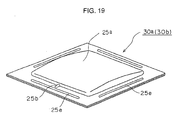
- FIG. 19 shows an example thereof, in which bead patterns are formed along straight side portions of the periphery of the stretch formed portion 25a.
- a sectional shape of each bead pattern and a position thereof on the holding surface of the associated die may be selected according to the type of the double sheet blank used in such a manner as to fulfill the foregoing two functions.
- FIGS. 21A and 21B illustrate another mode of a forming method according to the present invention.
- FIG. 21A is a perspective view of blanks 1 and 2, with a protuberance 1a of a size capable of being received within the channel-forming groove 10d being preformed in the blank 1 by, for example, press stamping at the position of the channel-forming groove 10d shown in FIG. 11.
- FIG. 21B is a sectional view of a holding surface portion of the upper and lower dies 10, 11 illustrated in FIG. 11, showing a state in which a double sheet blank 5 obtained by a full-circled welding of both blanks 1 and 2 is clamped by the upper and lower dies 10, 11.
- FIGS. 22A, 22B, and 22C illustrate another mode of a method which permits the stretch forming work to be done easily in the initial stage.
- FIG. 22A is a perspective view of a blank 1 and a blank 2, the blank 2 having a pierced hole 3 formed in a protuberance 2a which projects in a direction opposite to blank mating surfaces.
- FIG. 22B is a sectional view of a holding portion of an upper die 10 and a lower die 11, showing a state in which a blank 5 obtained by full-circled welding of the blanks 1 and 2 is clamped with both upper and lower dies 10, 11, the lower die 11 having a recess 11h of about the same inner contour shape as the outer contour shape of the protuberance 2a.
- the protuberance 2a Since the protuberance 2a is in a three-dimensional shape, it has rigidity, and a sealing effect is created when an O-ring 16 is crushed with the pressing force at the time of clamping the double sheet blank by the upper and lower dies.
- the depth of the aforesaid recess is set equal to or slightly smaller than the depth of the protuberance on blank. Further, since the force of crushing the O-ring in the vertical direction is transmitted to the O-ring through the side wall of the protuberance, it is recommended to set the size of the protuberance in such a manner that the O-ring is positioned near the side wall of the protuberance.
- Fluid fed from a thru-hole 11d formed in the bottom of the recess 11h immediately fills the internal space of the protuberance 2a, the blank 1 is pushed up locally toward a channel-forming groove 10d with the fluid pressure, and the fluid which has entered between the blanks 1 and 2 causes both blanks to bulge within die cavities 10b and 11b.
- the portion to be bulged of one or both blanks may be formed in a three-dimensional shape beforehand.
- FIGS. 23A, 23B, 23C, and 23D show examples of forming blanks in three-dimensional shapes beforehand by press stamping or any other suitable method and welding them throughout the whole circumference.
- FIG. 23A shows a blank ("preformed blank” hereinafter) 41 having a preformed portion 41a received within the upper die cavity and also having a protuberance 41b adjacent to the preformed portion 41a and received within the channel-forming groove 10d.
- FIG. 23B shows a preformed blank 42 having a preformed portion 42a received within the lower die cavity 11b and also having a pierced hole 3.
- Depths H1 and H2 of the preformed portions 41a and 42a, respectively, may be set appropriately in conformity with the shape of a hydroformed product to be obtained. Another part may be bonded to a predetermined inside position of each of the preformed portions 41a and 42a by a suitable method such as, for example, welding, adhesion, or brazing.
- FIG. 23C shows a double sheet blank ("preformed double sheet blank” hereinafter) 43 obtained by superimposing the preformed blanks 41 and 42 one on the other and laser-welding flanges 41c and 42c along a line 5b.
- the bonding may be done by adhesion or brazing. After the superimposition of both blanks, the vicinity of an edge portion may be partially bonded by, say, spot welding for ease of handling.
- FIG. 23D is a sectional view taken along a dot-dash line G in FIG. 23C.
- the feed of fluid from the pierced hole 3 to an internal space 43a may be done at a low fluid pressure. Since it can be done in a short time, it is possible to shorten the time required for the hydroforming work. Further, since the bulging action in the hydroforming work is applied to the preformed portions 41a and 42a having respective depths, it is possible to obtain a deeper formed part than in hydroforming flat sheets.
- a cold-rolled steel sheet SPCC (JIS G3141) having a thickness of 0.7 mm and a tensile strength of 320 MPa was cut into such blanks 1 and 2 of a square shape having a one-side length of 600 mm as shown in FIG. 9A.
- a pierced hole 3 having a diameter of 16 mm was formed in the blank 2. Both blanks 1 and 2 were put one on the other and laser-welded to afford a double sheet blank 5 having a welded line 5b such as that shown in FIG. 10B.
- the pressure of fluid (water emulsion) introduced into the pierced hole 3 from the thru-hole 11d was raised to 9.8 MPa to push up the blank 1 locally into a channel-forming groove 10d having a width w of 10 mm and a depth h of 2 mm, as shown in FIG. 12B, allowing the fluid to be introduced between the blanks 1 and 2 and thereby causing the blanks 1 and 2 to bulge into the die cavities 10b and 11b respectively.
- the fluid pressure was finally increased to 29.4 MPa and the bulging work was finished. Keeping the pressure of the medium, a punch 12 built into the lower die 11, as shown in FIG.
- An aluminum sheet A1100P (JIS H4000) having a thickness of 1 mm and a tensile strength of 95 MPa was cut into such a square blank 1 having a one-side length of 600 mm as shown in FIG. 9A. From the same aluminum sheet was also cut out a blank 2 of the same size as the blank 1, the blank 2 having a pierced hole 3 with a diameter of 16 mm. The blank 2, which was coated with an epoxy resin-based adhesive in a hatched area shown in FIG. 10C, was superimposed on the blank 1, followed by thermocompression bonding at 150°C, to fabricate a double sheet blank 7 in which the adhesive was hardened.
- the double sheet blank 7 was clamped with a holding force of 2450 kN.
- a cold-rolled steel sheet SPCC (JIS G3141) having a thickness of 0.6 mm and a tensile strength of 320 MPa was cut into a square blank 1 having a one-side length of 600 mm, which is shown in FIG. 22A.
- a cold-rolled steel sheet SPCC (JIS G3141) having a thickness of 0.8 mm and a tensile strength of 310 MPa was cut into a blank 2.
- the blank 2 was formed with a protuberance 2a having a diameter of 30 mm and a depth of 3 mm and a pierced hole 3 formed in a bottom of the protuberance 2a, the pierced hole 3 having a diameter of 16 mm.
- the blanks 1 and 2 were superimposed together and laser-welded to make a double sheet blank 5 having a welded line 5b, which is shown in FIG. 10B.
- An O-ring JIS B 2406) having a nominal No.
- P24 was fitted in a circular groove 11f having an outside diameter of 30 mm, an inside diameter D of 20.6 mm and a depth of 2.7 mm to provide a seal between the pierced hole 3 and a thru-hole 11d having an inside diameter of 8 mm.
- the pressure of fluid (water emulsion) which has filled the pierced hole 3 through the thru-hole 11d was raised to 9.8 MPa to push up the blank 1 locally into a channel-forming groove 10d shown in FIG. 12B, the channel-forming groove 10d having a width w of 10 mm and a depth h of 2 mm, allowing the fluid to enter between both blanks 1 and 2 and thereby causing both blanks to bulge into the die cavities 10b and 11b respectively.
- the fluid pressure was finally increased to 39.2 MPa and the bulging work was finished.
- a punch 12 built into the lower die 11, as shown in FIG. 15B was moved to pierce a thru-hole 52 having a planar size of 30 mm square without separation of slug 51, and the pressure of the medium was decreased. Thereafter, the fluid was discharged from the thru-hole 52 to get a stretch formed part 30a shown in FIG. 17A. Thereafter, by the method shown in FIG. 18, a flange 5a was cut off along a trimming line 25c located outside a welded line 5b1 of the stretch formed part to obtain a product.
- a cold-rolled steel sheet SPCC (JIS G3141) having a thickness of 0.7 mm and a tensile strength of 320 MPa was cut into a square blank 1 having a one-side length of 600 mm, which is shown in FIG. 9A.
- a punch 12 built into the lower die 11 was moved to pierce a thru-hole 52 having a planar size of 30 mm square while separating slug 51 and the pressure of the medium was decreased. Thereafter, the fluid was discharged from the thru-hole 52 to get a stretch formed part 30a shown in FIG. 17A. Thereafter, a flange 5a of this stretch formed part was cut to cut off the spot-welded portion, to obtain two upper and lower stretch formed parts.
- a cold-rolled steel sheet SPCC (JIS G3141) having a thickness of 0.7 mm and a tensile strength of 320 MPa was cut into a square blank having a one-side length of 600 mm.
- This square blank was then subjected to press stamping into such a preformed blank 41 as shown in FIG. 23A, the preformed blank 41 having a preformed portion 41a with a depth H1 of 20 mm and also having a protuberance 41b.
- Likewise, from the same cold-rolled steel sheet was cut out a square blank having a one-side length of 600 mm.
- This square blank was then subjected to press stamping to form a preformed portion 42a having a depth H2 of 20 mm, as shown in FIG. 23B. Further, a pierced hole 3 having a diameter of 16 mm was formed in the same blank to obtain a preformed blank 42.
- Both preformed blanks 41 and 42 were then put one on the other and laser-welded to fabricate a preformed double sheet blank 43 having a bonded line 5b shown in FIG. 23C.
- the double sheet blank 5 was clamped with a clamping force of 4900 kN.
- An O-ring (JIS B2406) having a nominal No. P24 was fitted in a circular groove 11f having an outside diameter of 30 mm, an inside diameter D of 20.6 mm and a depth of 2.7 mm to provide a seal between the pierced hole 3 and a thru-hole 11d formed in the lower die and having an inside diameter of 8 mm.
- An internal space 43a of the preformed double sheet blank was filled with fluid (water emulsion) introduced from the thru-hole 11d. Then, the fluid pressure was increased to 29. 4 MPa and the bulging work within the die cavities 10b and 11b was finished.
- a punch 12 built into the lower die 11 was moved to pierce a thru-hole 52 having a planar size of 30 mm square without separation of slug 51, as shown in FIG. 15B, and the pressure of the medium was decreased. Thereafter, the fluid was discharged from the punched thru-hole 52 to get a stretch formed part 30a shown in FIG. 17A. Then, by the method shown in FIG. 18, a flange was cut off along a trimming line 25c located outside a welded line 5b1 of the stretch formed part to obtain a product.
- both blanks are bonded together by laser welding continuously along a loop-like bonded line, or a method wherein both blanks are surface-bonded together in respective peripheral areas by adhesion or brazing, or a method wherein both blanks are bonded together in a discontinuous manner by spot welding. It is also possible to effect the hydroforming work without causing leakage of fluid in a merely superimposed state of two blanks without bonding.
- pressurized medium can be introduced between the mating surfaces of the blanks easily without causing leakage of the pressurized medium.
- the present invention brings about an outstanding effect industrially.
Landscapes
- Physics & Mathematics (AREA)
- Fluid Mechanics (AREA)
- Engineering & Computer Science (AREA)
- Mechanical Engineering (AREA)
- Shaping Metal By Deep-Drawing, Or The Like (AREA)
Claims (8)
- Procédé d'hydroformage de feuilles métalliques, comprenant le serrage de deux feuilles métalliques superposées (4) entre des surfaces de maintien (10a, 11a) de deux matrices supérieure et inférieure (10, 11) ayant respectivement des cavités de matrice (10b, 11b) de même contour intérieur qu'un contour extérieur de produit, et l'introduction d'un fluide entre les surfaces coopérantes des dites deux feuilles métalliques (4) et la mise en pression du fluide, afin d'engendrer un bombement des dites feuilles métalliques (4) dans les dites cavités de matrice (10a, 11b),
caractérisé en ce qu'un trou traversant (11d) pour introduire le fluide est ménagé dans une première des dites matrices, le dit trou traversant débouchant à la surface de maintien (11a) de cette matrice, un trou percé (3) pour introduire le fluide est positionné en correspondance du dit trou traversant (11d) ménagé dans la dite première matrice, le dit trou percé (3) étant ménagé dans une première des dites feuilles métalliques (4) dans une partie de cette feuille métallique, cette partie étant en contact avec la surface de maintien de la dite première matrice, et le fluide est introduit sous pression entre les surfaces coopérantes des dites feuilles métalliques par l'intermédiaire du dit trou percé (3) à partir du dit trou traversant, afin de provoquer un bombement des feuilles métalliques, dans lequel, après formage par étirage des dites feuilles métalliques par introduction du fluide sous pression entre les surfaces coopérantes des feuilles métalliques, des portions des feuilles métalliques, ces portions n'étant pas nécessaires comme produits et ces portions étant respectivement en contact avec les surfaces de maintien (10b, 11b) des dites matrices, sont coupées pour obtenir deux pièces formées (31, 32) en même temps. - Procédé d'hydroformage de feuilles métalliques selon la revendication 1, dans lequel une ou plusieurs portions à former par étirage d'une des dites feuilles métalliques (4) ou des deux feuilles est / sont préalablement formées en une configuration tridimensionnelle.
- Procédé d'hydroformage de feuilles métalliques selon la revendication 1 ou 2, dans lequel, après formage par étirage des dites feuilles métalliques (4), une ou les deux portions formées par étirage est / sont poinçonnées de manière à créer un ou plusieurs trous (52) au moyen d'un ou plusieurs poinçons (12) incorporés dans une des dites matrices ou les deux, ce qui permet d'évacuer le fluide par le ou les dits trous (52).
- Procédé d'hydroformage de feuilles métalliques selon une quelconque des revendications 1 à 3, comprenant le serrage de deux feuilles métalliques superposées (4), qui sont un simple empilage de deux ébauches sans liaison mutuelle, entre des surfaces de maintien (10a, 11a) de deux matrices supérieure et inférieure (10, 11) respectivement, caractérisé en ce que, lorsqu'on introduit le fluide sous pression entre des surfaces coopérantes des dites feuilles métalliques (4) et qu'on provoque ainsi le bombement des feuilles métalliques, une nervure (10g) et une rainure de réception de nervure (11g) entre les surfaces de maintien (10a, 11a) des dites matrices respectivement empêchent te fluide sous pression de fuir à l'extérieur de la collerette par l'interface des ébauches lors du serrage des feuilles métalliques (4).
- Procédé d'hydroformage de feuilles métalliques selon une quelconque des revendications 1 à 4, caractérisé en ce qu'un joint torique (16) est encastré dans une gorge circulaire (11f) autour d'un trou traversant (11b) présentant une surface de maintien (11a), et il est élastiquement déformé par la force de pression qui agit entre une surface de maintien (11a) et une feuille métallique (2), afin d'empêcher la fuite de fluide sous pression entre la dite surface de maintien (11a) et la dite feuille métallique (2).
- Matrice d'hydroformage de feuilles métalliques, comprenant une paire de matrices supérieure et inférieure (10, 11), respectivement, ayant des cavités de matrice (10b, 11b) du même contour intérieur qu'un contour extérieur du produit, caractérisée en ce qu'un trou traversant (11d) est ménagé dans une première des dites matrices pour introduire un fluide sous pression, le dit trou traversant aboutissant à une surface de maintien (11a) de la dite première matrice, et une rainure formant canal (10d) est formée dans une surface de maintien (10a) de l'autre matrice, la dite rainure formant canal s'étendant aux dites cavités de matrice (10b) à partir d'une position en face du dit trou traversant formé dans la dite première matrice, et en ce qu'une des dites matrices ou les deux possède / possèdent des moyens (12) pour ouvrir un ou plusieurs trous de sortie de fluide (52) sur une partie formée par étirage sur la pièce après formage (26).
- Matrice d'hydroformage de feuilles métalliques selon la revendication 6, dans laquelle une nervure (10g) et une rainure de réception de nervure (11g) sont prévues dans une surface de maintien (11a).
- Matrice d'hydroformage de feuilles métalliques selon la revendication 6 ou 7, dans laquelle une gorge circulaire (11f) pour contenir un joint torique (16) est prévue autour d'un trou traversant (11d) sur une surface de maintien (11a).
Applications Claiming Priority (4)
| Application Number | Priority Date | Filing Date | Title |
|---|---|---|---|
| JP2001139848 | 2001-05-10 | ||
| JP2001139848 | 2001-05-10 | ||
| JP2002108901A JP4082070B2 (ja) | 2001-05-10 | 2002-04-11 | 金属板の液圧バルジ成形方法、金型および成形品 |
| JP2002108901 | 2002-04-11 |
Publications (2)
| Publication Number | Publication Date |
|---|---|
| EP1256397A1 EP1256397A1 (fr) | 2002-11-13 |
| EP1256397B1 true EP1256397B1 (fr) | 2004-07-14 |
Family
ID=26614880
Family Applications (1)
| Application Number | Title | Priority Date | Filing Date |
|---|---|---|---|
| EP02291140A Expired - Lifetime EP1256397B1 (fr) | 2001-05-10 | 2002-05-06 | Procédé d'hydroformage de feuilles métalliques et appareil |
Country Status (5)
| Country | Link |
|---|---|
| US (1) | US6722009B2 (fr) |
| EP (1) | EP1256397B1 (fr) |
| JP (1) | JP4082070B2 (fr) |
| KR (1) | KR100488097B1 (fr) |
| DE (1) | DE60200731T2 (fr) |
Families Citing this family (27)
| Publication number | Priority date | Publication date | Assignee | Title |
|---|---|---|---|---|
| DE69232432T2 (de) | 1991-11-20 | 2002-07-18 | Canon K.K., Tokio/Tokyo | Verfahren zur Herstellung einer Halbleiteranordnung |
| US6825442B2 (en) * | 2003-01-06 | 2004-11-30 | General Motors Corporation | Tailor welded blank for fluid forming operation |
| CA2417248A1 (fr) * | 2003-01-17 | 2004-07-17 | Robert Walther | Methode de fabrication d'un goulot de remplissage de carburant |
| US7111447B2 (en) * | 2003-02-11 | 2006-09-26 | Avraham Moshe Rosenwasser | Method of forming jewelry articles |
| US7310878B2 (en) * | 2004-02-27 | 2007-12-25 | Gm Global Technology Operations, Inc. | Automotive lower body component method of manufacture |
| JP4502110B2 (ja) * | 2004-03-09 | 2010-07-14 | 住友金属工業株式会社 | 金属板の液圧バルジ加工装置および液圧バルジ加工方法 |
| EP1621267B1 (fr) | 2004-07-28 | 2008-07-16 | Nissan Motor Co., Ltd. | Préforme, procédé d'hydroformage, et pièce formée par hydroformage |
| JP4131332B2 (ja) * | 2004-07-28 | 2008-08-13 | 日産自動車株式会社 | 液圧成形方法 |
| US7200496B2 (en) * | 2005-06-02 | 2007-04-03 | Ford Global Technologies, Llc | Method of predicting wear of a die surface |
| DE102006010431B4 (de) * | 2006-03-03 | 2011-02-03 | Thyssenkrupp Steel Europe Ag | Verfahren und Vorrichtung zur Prüfung der Qualität einer metallischen Oberfläche |
| US7672816B1 (en) | 2006-05-17 | 2010-03-02 | Textron Innovations Inc. | Wrinkle-predicting process for hydroforming |
| US7975383B2 (en) * | 2006-07-28 | 2011-07-12 | Ford Global Technologies, Llc | Double hydroformed tube with integral reinforcement |
| JP5139038B2 (ja) * | 2007-11-19 | 2013-02-06 | 古河スカイ株式会社 | 金属中空構造体の製造方法 |
| US8171769B2 (en) * | 2009-01-27 | 2012-05-08 | Ford Global Technologies | Method of forming a flanged tubular member in hydroforming |
| US9302307B2 (en) * | 2009-02-16 | 2016-04-05 | Vari-Form, Inc. | Method of forming hollow body with flange |
| JP5018861B2 (ja) * | 2009-11-02 | 2012-09-05 | 住友金属工業株式会社 | 液圧バルジ加工装置および液圧バルジ加工方法 |
| DE102010022225A1 (de) * | 2010-04-28 | 2011-12-15 | J. Eberspächer GmbH & Co. KG | Wärmeübertragungsanordnung, Wärmeübertrager und Herstellungsverfahren |
| CN102806261A (zh) * | 2012-08-16 | 2012-12-05 | 哈尔滨工业大学 | 复杂曲面空腔零件液压成形装置及方法 |
| CN104096742B (zh) * | 2013-04-15 | 2016-08-10 | 宝山钢铁股份有限公司 | 保持工件壁平整度的液压冲孔方法及装置 |
| JP5866324B2 (ja) * | 2013-09-30 | 2016-02-17 | 本田技研工業株式会社 | 中空状構造部品のハイドロフォーム成形方法 |
| US10150354B2 (en) * | 2014-02-21 | 2018-12-11 | Ford Global Technologies, Llc | Automotive door structure for sail mounted mirrors |
| DE102019208111A1 (de) * | 2019-06-04 | 2020-12-10 | Heuft Besitzgesellschaft Gmbh & Co. Kg | Strukturelement einer Backkammer eines Backofens mit blasgewölbter Struktur |
| EP4222045A2 (fr) * | 2020-10-02 | 2023-08-09 | Zieta Prozessdesign Sploka Z Ograniczona Odpowiedzialnoscia | Cadre de carrosserie de véhicule, préformes d'élément de composant de cadre de carrosserie de véhicule, procédé de fabrication d'éléments de composant de cadre de carrosserie de véhicule, et éléments de composant de cadre de carrosserie de véhicule |
| DE102020216059A1 (de) * | 2020-12-16 | 2022-06-23 | Mahle International Gmbh | Verfahren zur Herstellung eines Wärmeübertragers |
| KR102308688B1 (ko) * | 2021-02-24 | 2021-10-05 | 대우공업 (주) | 실링기능이 향상된 하이드로포밍 성형장치 |
| FR3125974A1 (fr) | 2021-08-05 | 2023-02-10 | Airbus Operations | Procédé et dispositif de fabrication de pièce à partir d’une plaque en matériau déformable, en particulier pour un bord d’un élément d’un aéronef. |
| FR3125975A1 (fr) * | 2021-08-05 | 2023-02-10 | Airbus Operations | Procédé et dispositif de fabrication de pièce à partir d’un coussin en matériau déformable, en particulier pour un bord d’un élément d’un aéronef. |
Family Cites Families (21)
| Publication number | Priority date | Publication date | Assignee | Title |
|---|---|---|---|---|
| US3024525A (en) * | 1957-08-28 | 1962-03-13 | Goodyear Aircraft Corp | Method of making multi-walled concavo-convex objects |
| US3807009A (en) * | 1971-04-06 | 1974-04-30 | J Ostbo | Method of manufacturing curved tube sections and the like |
| US3927817A (en) * | 1974-10-03 | 1975-12-23 | Rockwell International Corp | Method for making metallic sandwich structures |
| US4331284A (en) * | 1980-03-14 | 1982-05-25 | Rockwell International Corporation | Method of making diffusion bonded and superplastically formed structures |
| US4361262A (en) * | 1980-06-12 | 1982-11-30 | Rockwell International Corporation | Method of making expanded sandwich structures |
| JPS5966941A (ja) * | 1982-10-07 | 1984-04-16 | Mitsubishi Heavy Ind Ltd | モ−ルドの製造方法 |
| JPS63295029A (ja) | 1987-05-25 | 1988-12-01 | Riken Corp | 管体の製造方法 |
| US5157969A (en) * | 1989-11-29 | 1992-10-27 | Armco Steel Co., L.P. | Apparatus and method for hydroforming sheet metal |
| US5372027A (en) * | 1989-11-29 | 1994-12-13 | Armco Steel Company, L.P. | Controlled material flow hydroforming |
| DE4232161A1 (de) * | 1992-09-25 | 1994-03-31 | Audi Ag | Verfahren zum Herstellen eines Hohlkörpers |
| DE4427140C1 (de) * | 1994-07-30 | 1995-10-19 | Krupp Ag Hoesch Krupp | Verfahren zur Herstellung eines hohlen Bauteils mittels des Innenhochdruckumformverfahrens und Werkzeug zur Durchführung des Verfahrens |
| DE4434799A1 (de) | 1994-09-29 | 1996-04-04 | Smg Sueddeutsche Maschinenbau | Verfahren und Vorrichtung zum Umformen von Metallblech |
| JP3171544B2 (ja) | 1995-07-20 | 2001-05-28 | カルソニックカンセイ株式会社 | 金属管体の製造方法 |
| DE19535870C2 (de) * | 1995-07-24 | 2002-07-11 | Blz Gmbh | Verfahren zum Herstellen von schalenförmigen Hohlstrukturen aus gedoppelten Blechzuschnitten mittels Innenhochdruckumformen |
| US5692406A (en) * | 1996-09-27 | 1997-12-02 | Mcdonnell Douglas Corporation | Gas inlet for a superplastic forming die and method of use |
| US5737954A (en) * | 1996-11-15 | 1998-04-14 | Mcdonnell Douglas Corporation | Superplastic forming with direct electrical heating |
| US5816089A (en) * | 1996-11-26 | 1998-10-06 | Dana Corporation | Hydroforming apparatus having in-die hole piercing capabilities and a slug ejection system using hydroforming fluid |
| DE19719426B4 (de) * | 1997-05-12 | 2005-06-16 | Dr. Meleghy Hydroforming Gmbh & Co. Kg | Verfahren und Vorrichtung zum Herstellen eines Hohlkörpers |
| DE19742444C2 (de) | 1997-09-26 | 1999-11-18 | Daimler Chrysler Ag | Verfahren zur Herstellung eines Hohlkörpers aus zwei Metallplatinen |
| JPH11347643A (ja) | 1998-06-12 | 1999-12-21 | Nissan Motor Co Ltd | 板材の液圧バルジ成形方法 |
| US6055715A (en) * | 1999-05-03 | 2000-05-02 | General Motors Corporation | Method for hydroforming a hollow sheet metal body part |
-
2002
- 2002-04-11 JP JP2002108901A patent/JP4082070B2/ja not_active Expired - Fee Related
- 2002-05-06 KR KR10-2002-0024796A patent/KR100488097B1/ko not_active Expired - Lifetime
- 2002-05-06 DE DE60200731T patent/DE60200731T2/de not_active Expired - Lifetime
- 2002-05-06 EP EP02291140A patent/EP1256397B1/fr not_active Expired - Lifetime
- 2002-05-09 US US10/141,074 patent/US6722009B2/en not_active Expired - Lifetime
Also Published As
| Publication number | Publication date |
|---|---|
| US6722009B2 (en) | 2004-04-20 |
| US20020166222A1 (en) | 2002-11-14 |
| JP4082070B2 (ja) | 2008-04-30 |
| DE60200731T2 (de) | 2005-07-21 |
| KR20020086238A (ko) | 2002-11-18 |
| EP1256397A1 (fr) | 2002-11-13 |
| KR100488097B1 (ko) | 2005-05-06 |
| JP2003025022A (ja) | 2003-01-28 |
| DE60200731D1 (de) | 2004-08-19 |
Similar Documents
| Publication | Publication Date | Title |
|---|---|---|
| EP1256397B1 (fr) | Procédé d'hydroformage de feuilles métalliques et appareil | |
| US8297096B2 (en) | Method for hydroforming and hydroformed product | |
| JP4846949B2 (ja) | 圧縮ハイドロフォーミング | |
| US7293442B1 (en) | Method for hydroforming a ring-shaped tubular structure | |
| KR100948711B1 (ko) | 관통 구멍을 갖는 금속제 부재 및 그 제조 방법 | |
| JP4696334B2 (ja) | ハイドロフォーム方法 | |
| JP4052297B2 (ja) | 液圧成形方法および液圧成形品 | |
| JPH06218440A (ja) | 集合ブランク部材の成形方法および装置 | |
| JP4826436B2 (ja) | 金属板のハイドロフォーム加工装置、加工方法およびこれらを用いた加工製品 | |
| JP3646688B2 (ja) | 中空状構造部品の液圧成形方法 | |
| CN110369594B (zh) | 一种制造整体式后桥壳零件的成形方法 | |
| JP3627662B2 (ja) | 重ね合わせ板材の液圧成形方法 | |
| JP4281463B2 (ja) | 液圧成形方法および液圧成形装置 | |
| JP3654210B2 (ja) | 重ね合せ板材のハイドロフォーム成形方法、その装置および重ね合せ板材 | |
| JP4670334B2 (ja) | 予備成形体、液圧成形方法および液圧成形品 | |
| JP2004098069A (ja) | 中空部材の液圧穴抜き加工方法および液圧穴抜き加工装置 | |
| JP4556585B2 (ja) | 液圧バルジ成形品および液圧バルジ成形方法 | |
| JP2001225114A (ja) | ハイドロフォーム加工方法 | |
| JP4639726B2 (ja) | 液圧成形用予備成形体、液圧成形方法および液圧成形品 | |
| JP2009262207A (ja) | 重ね合わせ板材のハイドロフォーム成形方法 | |
| JP2007075844A (ja) | 液圧バルジ加工製品およびその液圧バルジ成形方法 | |
| JP3904829B2 (ja) | パイプ体、パイプ体の製造方法及びそのパイプ体が用いられた画像形成装置 | |
| JP2004195508A (ja) | 液圧成形方法および液圧成形装置 | |
| JP2007007717A (ja) | 予備成形体、液圧成形方法および液圧成形部材 | |
| CN121446905A (zh) | 一种液压胀型模具内的零件定位孔的冲孔方法及装置 |
Legal Events
| Date | Code | Title | Description |
|---|---|---|---|
| PUAI | Public reference made under article 153(3) epc to a published international application that has entered the european phase |
Free format text: ORIGINAL CODE: 0009012 |
|
| 17P | Request for examination filed |
Effective date: 20020514 |
|
| AK | Designated contracting states |
Kind code of ref document: A1 Designated state(s): AT BE CH CY DE DK ES FI FR GB GR IE IT LI LU MC NL PT SE TR |
|
| AX | Request for extension of the european patent |
Free format text: AL;LT;LV;MK;RO;SI |
|
| 17Q | First examination report despatched |
Effective date: 20030129 |
|
| AKX | Designation fees paid |
Designated state(s): DE FR GB IT |
|
| GRAP | Despatch of communication of intention to grant a patent |
Free format text: ORIGINAL CODE: EPIDOSNIGR1 |
|
| RTI1 | Title (correction) |
Free format text: METALLIC SHEET HYDROFORMING METHOD AND FORMING DIE |
|
| RIN1 | Information on inventor provided before grant (corrected) |
Inventor name: KOJIMA, MASAYASU,C/O SUMITOMO METAL IND., LTD. Inventor name: UCHIDA, MITSUTOSHI,C/O SUMITOMO METAL IND., LTD. |
|
| GRAS | Grant fee paid |
Free format text: ORIGINAL CODE: EPIDOSNIGR3 |
|
| GRAA | (expected) grant |
Free format text: ORIGINAL CODE: 0009210 |
|
| AK | Designated contracting states |
Kind code of ref document: B1 Designated state(s): DE FR GB IT |
|
| REG | Reference to a national code |
Ref country code: GB Ref legal event code: FG4D |
|
| REF | Corresponds to: |
Ref document number: 60200731 Country of ref document: DE Date of ref document: 20040819 Kind code of ref document: P |
|
| ET | Fr: translation filed | ||
| PLBE | No opposition filed within time limit |
Free format text: ORIGINAL CODE: 0009261 |
|
| STAA | Information on the status of an ep patent application or granted ep patent |
Free format text: STATUS: NO OPPOSITION FILED WITHIN TIME LIMIT |
|
| 26N | No opposition filed |
Effective date: 20050415 |
|
| REG | Reference to a national code |
Ref country code: GB Ref legal event code: 732E Free format text: REGISTERED BETWEEN 20131010 AND 20131016 |
|
| REG | Reference to a national code |
Ref country code: FR Ref legal event code: TP Owner name: NIPPON STEEL & SUMITOMO METAL CORPORATION, JP Effective date: 20131108 |
|
| REG | Reference to a national code |
Ref country code: DE Ref legal event code: R082 Ref document number: 60200731 Country of ref document: DE Representative=s name: MUELLER-BORE & PARTNER PATENTANWAELTE PARTG MB, DE |
|
| REG | Reference to a national code |
Ref country code: DE Ref legal event code: R081 Ref document number: 60200731 Country of ref document: DE Owner name: NIPPON STEEL & SUMITOMO METAL CORPORATION, JP Free format text: FORMER OWNER: SUMITOMO METAL INDUSTRIES, LTD., OSAKA, JP Effective date: 20140402 Ref country code: DE Ref legal event code: R082 Ref document number: 60200731 Country of ref document: DE Representative=s name: MUELLER-BORE & PARTNER PATENTANWAELTE PARTG MB, DE Effective date: 20140402 |
|
| REG | Reference to a national code |
Ref country code: FR Ref legal event code: PLFP Year of fee payment: 15 |
|
| REG | Reference to a national code |
Ref country code: FR Ref legal event code: PLFP Year of fee payment: 16 |
|
| REG | Reference to a national code |
Ref country code: FR Ref legal event code: PLFP Year of fee payment: 17 |
|
| REG | Reference to a national code |
Ref country code: DE Ref legal event code: R082 Ref document number: 60200731 Country of ref document: DE Representative=s name: MUELLER-BORE & PARTNER PATENTANWAELTE PARTG MB, DE Ref country code: DE Ref legal event code: R081 Ref document number: 60200731 Country of ref document: DE Owner name: NIPPON STEEL CORP., JP Free format text: FORMER OWNER: NIPPON STEEL & SUMITOMO METAL CORPORATION, TOKYO, JP |
|
| PGFP | Annual fee paid to national office [announced via postgrant information from national office to epo] |
Ref country code: IT Payment date: 20200414 Year of fee payment: 19 Ref country code: GB Payment date: 20200430 Year of fee payment: 19 |
|
| PGFP | Annual fee paid to national office [announced via postgrant information from national office to epo] |
Ref country code: FR Payment date: 20210412 Year of fee payment: 20 Ref country code: DE Payment date: 20210408 Year of fee payment: 20 |
|
| GBPC | Gb: european patent ceased through non-payment of renewal fee |
Effective date: 20210506 |
|
| PG25 | Lapsed in a contracting state [announced via postgrant information from national office to epo] |
Ref country code: GB Free format text: LAPSE BECAUSE OF NON-PAYMENT OF DUE FEES Effective date: 20210506 |
|
| REG | Reference to a national code |
Ref country code: DE Ref legal event code: R071 Ref document number: 60200731 Country of ref document: DE |
|
| PG25 | Lapsed in a contracting state [announced via postgrant information from national office to epo] |
Ref country code: IT Free format text: LAPSE BECAUSE OF NON-PAYMENT OF DUE FEES Effective date: 20200506 |
|
| PG25 | Lapsed in a contracting state [announced via postgrant information from national office to epo] |
Ref country code: IT Free format text: LAPSE BECAUSE OF NON-PAYMENT OF DUE FEES Effective date: 20210506 |