EP1255666B1 - Installation de freinage - Google Patents
Installation de freinage Download PDFInfo
- Publication number
- EP1255666B1 EP1255666B1 EP01905690A EP01905690A EP1255666B1 EP 1255666 B1 EP1255666 B1 EP 1255666B1 EP 01905690 A EP01905690 A EP 01905690A EP 01905690 A EP01905690 A EP 01905690A EP 1255666 B1 EP1255666 B1 EP 1255666B1
- Authority
- EP
- European Patent Office
- Prior art keywords
- pressure
- pump
- valve
- motor
- brake unit
- Prior art date
- Legal status (The legal status is an assumption and is not a legal conclusion. Google has not performed a legal analysis and makes no representation as to the accuracy of the status listed.)
- Expired - Lifetime
Links
- 230000008878 coupling Effects 0.000 claims description 3
- 238000010168 coupling process Methods 0.000 claims description 3
- 238000005859 coupling reaction Methods 0.000 claims description 3
- 241001071861 Lethrinus genivittatus Species 0.000 claims 1
- 238000007789 sealing Methods 0.000 description 12
- 238000010276 construction Methods 0.000 description 3
- 238000011109 contamination Methods 0.000 description 2
- 238000010586 diagram Methods 0.000 description 2
- 230000006870 function Effects 0.000 description 2
- 238000002347 injection Methods 0.000 description 2
- 239000007924 injection Substances 0.000 description 2
- 238000009434 installation Methods 0.000 description 2
- 238000005352 clarification Methods 0.000 description 1
- 239000012530 fluid Substances 0.000 description 1
- 230000010354 integration Effects 0.000 description 1
- 230000010349 pulsation Effects 0.000 description 1
Images


Classifications
-
- B—PERFORMING OPERATIONS; TRANSPORTING
- B60—VEHICLES IN GENERAL
- B60T—VEHICLE BRAKE CONTROL SYSTEMS OR PARTS THEREOF; BRAKE CONTROL SYSTEMS OR PARTS THEREOF, IN GENERAL; ARRANGEMENT OF BRAKING ELEMENTS ON VEHICLES IN GENERAL; PORTABLE DEVICES FOR PREVENTING UNWANTED MOVEMENT OF VEHICLES; VEHICLE MODIFICATIONS TO FACILITATE COOLING OF BRAKES
- B60T17/00—Component parts, details, or accessories of power brake systems not covered by groups B60T8/00, B60T13/00 or B60T15/00, or presenting other characteristic features
- B60T17/02—Arrangements of pumps or compressors, or control devices therefor
-
- B—PERFORMING OPERATIONS; TRANSPORTING
- B60—VEHICLES IN GENERAL
- B60T—VEHICLE BRAKE CONTROL SYSTEMS OR PARTS THEREOF; BRAKE CONTROL SYSTEMS OR PARTS THEREOF, IN GENERAL; ARRANGEMENT OF BRAKING ELEMENTS ON VEHICLES IN GENERAL; PORTABLE DEVICES FOR PREVENTING UNWANTED MOVEMENT OF VEHICLES; VEHICLE MODIFICATIONS TO FACILITATE COOLING OF BRAKES
- B60T13/00—Transmitting braking action from initiating means to ultimate brake actuator with power assistance or drive; Brake systems incorporating such transmitting means, e.g. air-pressure brake systems
- B60T13/10—Transmitting braking action from initiating means to ultimate brake actuator with power assistance or drive; Brake systems incorporating such transmitting means, e.g. air-pressure brake systems with fluid assistance, drive, or release
- B60T13/12—Transmitting braking action from initiating means to ultimate brake actuator with power assistance or drive; Brake systems incorporating such transmitting means, e.g. air-pressure brake systems with fluid assistance, drive, or release the fluid being liquid
- B60T13/14—Transmitting braking action from initiating means to ultimate brake actuator with power assistance or drive; Brake systems incorporating such transmitting means, e.g. air-pressure brake systems with fluid assistance, drive, or release the fluid being liquid using accumulators or reservoirs fed by pumps
- B60T13/148—Arrangements for pressure supply
-
- B—PERFORMING OPERATIONS; TRANSPORTING
- B60—VEHICLES IN GENERAL
- B60T—VEHICLE BRAKE CONTROL SYSTEMS OR PARTS THEREOF; BRAKE CONTROL SYSTEMS OR PARTS THEREOF, IN GENERAL; ARRANGEMENT OF BRAKING ELEMENTS ON VEHICLES IN GENERAL; PORTABLE DEVICES FOR PREVENTING UNWANTED MOVEMENT OF VEHICLES; VEHICLE MODIFICATIONS TO FACILITATE COOLING OF BRAKES
- B60T8/00—Arrangements for adjusting wheel-braking force to meet varying vehicular or ground-surface conditions, e.g. limiting or varying distribution of braking force
- B60T8/32—Arrangements for adjusting wheel-braking force to meet varying vehicular or ground-surface conditions, e.g. limiting or varying distribution of braking force responsive to a speed condition, e.g. acceleration or deceleration
- B60T8/34—Arrangements for adjusting wheel-braking force to meet varying vehicular or ground-surface conditions, e.g. limiting or varying distribution of braking force responsive to a speed condition, e.g. acceleration or deceleration having a fluid pressure regulator responsive to a speed condition
- B60T8/36—Arrangements for adjusting wheel-braking force to meet varying vehicular or ground-surface conditions, e.g. limiting or varying distribution of braking force responsive to a speed condition, e.g. acceleration or deceleration having a fluid pressure regulator responsive to a speed condition including a pilot valve responding to an electromagnetic force
- B60T8/3615—Electromagnetic valves specially adapted for anti-lock brake and traction control systems
- B60T8/3675—Electromagnetic valves specially adapted for anti-lock brake and traction control systems integrated in modulator units
- B60T8/368—Electromagnetic valves specially adapted for anti-lock brake and traction control systems integrated in modulator units combined with other mechanical components, e.g. pump units, master cylinders
-
- B—PERFORMING OPERATIONS; TRANSPORTING
- B60—VEHICLES IN GENERAL
- B60T—VEHICLE BRAKE CONTROL SYSTEMS OR PARTS THEREOF; BRAKE CONTROL SYSTEMS OR PARTS THEREOF, IN GENERAL; ARRANGEMENT OF BRAKING ELEMENTS ON VEHICLES IN GENERAL; PORTABLE DEVICES FOR PREVENTING UNWANTED MOVEMENT OF VEHICLES; VEHICLE MODIFICATIONS TO FACILITATE COOLING OF BRAKES
- B60T8/00—Arrangements for adjusting wheel-braking force to meet varying vehicular or ground-surface conditions, e.g. limiting or varying distribution of braking force
- B60T8/32—Arrangements for adjusting wheel-braking force to meet varying vehicular or ground-surface conditions, e.g. limiting or varying distribution of braking force responsive to a speed condition, e.g. acceleration or deceleration
- B60T8/34—Arrangements for adjusting wheel-braking force to meet varying vehicular or ground-surface conditions, e.g. limiting or varying distribution of braking force responsive to a speed condition, e.g. acceleration or deceleration having a fluid pressure regulator responsive to a speed condition
- B60T8/40—Arrangements for adjusting wheel-braking force to meet varying vehicular or ground-surface conditions, e.g. limiting or varying distribution of braking force responsive to a speed condition, e.g. acceleration or deceleration having a fluid pressure regulator responsive to a speed condition comprising an additional fluid circuit including fluid pressurising means for modifying the pressure of the braking fluid, e.g. including wheel driven pumps for detecting a speed condition, or pumps which are controlled by means independent of the braking system
- B60T8/4031—Pump units characterised by their construction or mounting
-
- F—MECHANICAL ENGINEERING; LIGHTING; HEATING; WEAPONS; BLASTING
- F04—POSITIVE - DISPLACEMENT MACHINES FOR LIQUIDS; PUMPS FOR LIQUIDS OR ELASTIC FLUIDS
- F04C—ROTARY-PISTON, OR OSCILLATING-PISTON, POSITIVE-DISPLACEMENT MACHINES FOR LIQUIDS; ROTARY-PISTON, OR OSCILLATING-PISTON, POSITIVE-DISPLACEMENT PUMPS
- F04C15/00—Component parts, details or accessories of machines, pumps or pumping installations, not provided for in groups F04C2/00 - F04C14/00
- F04C15/0057—Driving elements, brakes, couplings, transmission specially adapted for machines or pumps
- F04C15/0061—Means for transmitting movement from the prime mover to driven parts of the pump, e.g. clutches, couplings, transmissions
-
- F—MECHANICAL ENGINEERING; LIGHTING; HEATING; WEAPONS; BLASTING
- F04—POSITIVE - DISPLACEMENT MACHINES FOR LIQUIDS; PUMPS FOR LIQUIDS OR ELASTIC FLUIDS
- F04C—ROTARY-PISTON, OR OSCILLATING-PISTON, POSITIVE-DISPLACEMENT MACHINES FOR LIQUIDS; ROTARY-PISTON, OR OSCILLATING-PISTON, POSITIVE-DISPLACEMENT PUMPS
- F04C2/00—Rotary-piston machines or pumps
- F04C2/08—Rotary-piston machines or pumps of intermeshing-engagement type, i.e. with engagement of co-operating members similar to that of toothed gearing
- F04C2/10—Rotary-piston machines or pumps of intermeshing-engagement type, i.e. with engagement of co-operating members similar to that of toothed gearing of internal-axis type with the outer member having more teeth or tooth-equivalents, e.g. rollers, than the inner member
- F04C2/102—Rotary-piston machines or pumps of intermeshing-engagement type, i.e. with engagement of co-operating members similar to that of toothed gearing of internal-axis type with the outer member having more teeth or tooth-equivalents, e.g. rollers, than the inner member the two members rotating simultaneously around their respective axes
Definitions
- the present invention relates to an electronically controllable brake system for motor vehicles with a pressure generating device for generating a hydraulic pressure and a drive device therefor.
- a designed as a stepped piston pump pump is for example from the German patent application DE 43 16 986 A1 known.
- Piston pumps in this application have the disadvantage of function-related pressure pulsation, which depends in particular on the number of pistons used. This causes a certain noise level, which may be unacceptable in the passenger compartment. Especially when using a piston pump in EHB systems (electrohydraulic brake system) this circumstance can lead to a decrease in comfort.
- the object of the present invention is to avoid the disadvantages of the prior art, and to develop an electronically controlled brake system of the type mentioned in such a way that only a lower noise level during the pressure generating phases, especially in EHB systems occurs.
- Another aim relates to a cheaper version of the engine mount.
- An advantage of the present invention is that in an internal gear pump only moments are transmitted, d. H. that act on the engine mount lower radial forces than a radial piston pump. This allows a pulsation-poor operation.
- a shaft of the drive device is guided in a bearing, wherein the bearing is arranged in a valve block of a hydraulic control unit.
- the bearing plate can be formed in this case as a simple plastic injection molded part.
- the internal gear pump is an independently manageable unit. This allows the pump to be pre-tested externally.
- the internal gear pump is designed as a cartridge. This results in a simple integration of the pump in a HCU electronically controlled brake system.
- a pressure-side connection of the pressure-generating device is connected to a valve arrangement designed as a cartridge, wherein the valve arrangement has a check valve and a pressure-limiting valve.
- the valve arrangement has a check valve and a pressure-limiting valve.
- valve assembly is mounted in a valve block of a hydraulic control unit by a clinching or Verstemmriv.
- a particularly compact design of the pump results when the pump has a housing part and a cover part, wherein the housing part and the cover part are connected to each other by means of a Lancierharm.
- the Lancierharm also contamination of the system is avoided by chips.
- a low-pressure space is formed in the pump intake region of the pressure-generating device.
- the low-pressure space is connected to a low-pressure accumulator or the like.
- a coupling device provided for connecting the drive device and the pressure-generating device is arranged in the low-pressure space.
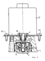
- FIG. 1 schematically the engine-pump assembly is shown in an exploded, partial cross-sectional view schematically.
- a reference numeral 1 denotes a valve block or HCU block of a hydraulic control unit of an electronically controlled brake system.
- the recess 2 serves to receive an internal gear pump 4, which in the following in connection with the FIGS. 2a and 2b is explained in detail with respect to the structure. While the internal gear pump 4 is inserted flush in a lower portion of the recess 2, a motor 5 is fixed in the opposite upper portion of the recess 2.
- the recess 3 serves to receive a valve assembly 6 designed as a cartridge or cartridge.
- Valve assembly 6 will be described below with reference to FIGS Fig. 3 explained in more detail.
- the motor shaft 7 is coupled via a coupling 8 without transverse force with a pin 10 formed at the upper end of the pinion shaft 9.
- the motor shaft 7 runs wet in the suction chamber 11 and is sealed to a bearing plate 12 of the motor 5 by means of a sleeve 13.
- an integrated in the bearing plate 12 O-ring seal 14 is provided for external sealing of the suction chamber 11 an integrated in the bearing plate 12 O-ring seal 14 is provided.
- the valve block 1 has a trailing port 15 of the surge tank. Opposite is formed in the valve block 1, a return port 16 for control valves.
- the connections 15, 16 are connected to the suction chamber 11.
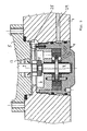
- Fig. 2a is shown schematically a cross-sectional view of the internal gear pump 4 used.
- the internal gear pump 4 has a pump housing 17, a pump cover 18 and a ring gear 19.
- the ring gear 19 is a single or multi-part pinion 20 runs (see Fig. 2b )
- the ring gear 19 is radially supported by a sliding ring 23 in the pump housing 17.
- the pump cover 18 is provided with an integrated suction filter 24 and thus forms a suction port 25 of the internal gear pump 4.
- the pump cover 18 is caulked after pre-assembly of the internal parts with the pump housing 17.
- the pump housing 17 of the internal gear pump 4 is formed substantially in one piece and has clinching contours 26 on its periphery. Further, the pump housing 17 receives an annular pressure port 27 and a pressure filter 28 in itself.
- Fig. 2b is a schematic plan view of a section along the line IIb-IIb of Fig. 2a shown.
- Fig. 3 the structure of the valve assembly 6 designed as a cartridge is explained in further detail.
- a pressure port 29 of the valve cartridge 6 is connected in the intended installation position with the annular pressure port 27 of the internal gear pump 4.
- the valve cartridge 6 has a check valve 30 and a pressure limiting valve 31.
- the housing 32 of the valve cartridge 6 is formed in one piece. On the outer circumference of the housing 32, as well as on the outer circumference of the pump housing 17, clinching contours 33 are formed to secure the valve cartridge in the valve block 1.
- An annular channel 34 of the check valve 30 supplies the control valves or the memory with the necessary supply pressure.
- valve cartridge 6 is an independently manageable unit, which can be externally pretested in particular.
- FIG. 4 shown the motor-pump unit with installed in the valve block 1 state.
- Fig. 5 shows a schematic hydraulic block diagram of the motor-pump assembly, and the valve assembly. 6
- the motor 5 a massive motor flange 35, which centered a bearing 36 and a sleeve or shaft seal 13.
- the motor forces introduced by the motor shaft 7 are received in the motor flange 35.
- the sealing ring 14 ensures the sealing of the suction chamber 11, in which the clutch 8 transmits during operation the engine torque to the pump 4, which is preferably designed as an internal gear pump.
- the motor flange 35 is connected via a parallel to the pump axis formed contact 37 with the valve block 1.
- the motor flange 35 On the side facing the valve block 1, the motor flange 35 has a centering collar 38, which ensures the alignment of the motor shaft 4 and the pump shaft 9.
- FIG. 7 An embodiment of the present invention is in Fig. 7 shown. Unlike the in Fig. 6
- the centering collar 38 (see FIG Fig. 6 ) accounted for.
- the valve block 1 has at the location of the implementation of the motor shaft 7 on a Lagerzentrierbohrung 39, which on the one hand receives the rotor forces of the motor 5 and on the other hand, the motor shaft 4 centered.
- the sealing of the suction chamber 11 is thus ensured by the closed up to the Lagerzentrierbohrung 39 training the motor 5 facing side of the valve block 1 together with the shaft seal 13.
- Fig. 6 also not shown such a massive motor flange 35 (see Fig.
- a simple bearing plate 40 which is preferably formed as a plastic injection part due to the low loads, is sufficient in operation completely.
- the housing of the motor 5 is fastened to the valve block 1 via a screw connection 41.
- the shorter length of the internal gear pump 4 with respect to in Fig. 6 Example shown is achieved in that the two pump housing halves 17, 18 are connected by Lancieren. In this way, a play-free Connection achieved in addition to the advantage of saving space by the short construction, especially compared with screw, also prevents contamination of the system by chips.
- a component-optimized connection of motor 5 and pump 6 by means of the valve block 1 is in the in Fig. 8 illustrated embodiment of the present invention.
- a filter (not shown) is integrated in the suction chamber 6.
- a partial interference fit between the pump housing 17 and the valve block 1 takes over the torque support and prevents detachment of the pump 4 from the valve block 1. Due to the optimized connection, the screw 41 (see 6 and 7 ) may be replaced by a riveted joint indicated at 43.
- FIG. 9 Fig. 3 is a schematic cross-sectional view of an example for illustrative purposes only. Also in the example of Fig. 9 flows pressure fluid through the suction bore 25 by the operation of the internal gear pump 4, which simultaneously provides an increase in pressure through the pressure bore 29 in a (not shown) memory.
- a (not shown) memory For more details of in Fig. 9 illustrated example is particularly to the description and the drawing according to Fig. 1 to 5 of the first example. It should be noted that the sealing sleeve 13 is loaded in the preferred EHB case only with low suction pressures.
- Fig. 10 In contrast to this is in Fig. 10 just for technical explanation, another example shown.
- the construction of the pumps in Fig. 9 and 10 is generally similar, but the pump preferred for the OHB application has a larger design.
- the pressures introduced through the suction port 25 may be substantially higher than in EHB case, and for example about 200 bar. Therefore, in the example according to Fig. 10 opposite to the Fig. 9 illustrated example, in addition to the sealing sleeve 13, a low-pressure space 44 provided in Pumpenansaug Scheme.
- the low pressure space is connected to a (not shown) low pressure accumulator or container via the channels 45 (in the motor housing 5) and 46 (in the valve block 1).
- the low pressure space 44 is formed by a cylindrically shaped sleeve portion 47, which is sealed with an inner sealing ring 48 and an outer sealing ring 49.
- the inner sealing ring 48 is formed in a corresponding recess on the motor 5 side facing the sleeve portion 47.
- the outer sealing ring 49 is arranged in a stepped bore between the engine 5 and the valve block 1.
- the example shown is the pressure load of the sealing sleeve 13, which minimizes particularly high in an OHB application. Otherwise, the problem of high-pressure, rotating radial shaft seal is difficult to solve. The leakage from the pump can thus drain.
Claims (8)
- Installation de freinage à régulation électronique pour véhicules automobiles avec un dispositif de production de pression dans un bloc de soupapes (1) d'une unité de régulation hydraulique, avec un dispositif d'entraînement comprenant un arbre de moteur (7) pour le dispositif de production de pression, dans laquelle le dispositif de production de pression est réalisé sous la forme d'une pompe à engrenage intérieur (4) disposée dans le bloc de soupapes (1) et la pompe à engrenage intérieur (4) est réalisée sous la forme d'une cartouche en vue de sa manipulation et de son test préliminaire, caractérisée en ce que l'arbre de moteur (7) du dispositif d'entraînement est guidé dans un palier (36), qui est logé dans un alésage de centrage de palier (39) dans le bloc de soupapes (1).
- Installation de freinage selon la revendication 1, caractérisée en ce que la pompe à engrenage intérieur (4) est fixée dans un bloc de soupapes (1) d'une unité de régulation hydraulique au moyen d'au moins un assemblage par encliquetage ou emboîtement (26).
- Installation de freinage selon l'une quelconque des revendications 1 à 2, caractérisée en ce qu'un raccord côté pression du dispositif de production de pression est raccordé à un dispositif de soupapes (6) réalisé en forme de cartouche, dans laquelle le dispositif de soupapes (6) comprend un clapet anti-retour (30) et une soupape de limitation de pression (31).
- Installation de pression selon la revendication 3, caractérisée en ce que le dispositif de soupapes (6) est fixé dans un bloc de soupapes (1) d'une unité de régulation hydraulique au moyen d'un assemblage par encliquetage ou emboîtement (33).
- Installation de freinage selon l'une quelconque des revendications 1 à 4, caractérisée en ce que le dispositif de production de pression comprend une partie de boîtier (17) et une partie de couvercle (18), dans laquelle la partie de boîtier (17) et la partie de couvercle (18) sont assemblées l'une à l'autre au moyen d'un assemblage à lancer.
- Installation de freinage selon l'une quelconque des revendications 1 à 5, caractérisée en ce qu'une chambre basse pression (44) est formée dans la région d'aspiration de la pompe du dispositif de production de pression.
- Installation de freinage selon la revendication 6, caractérisée en ce que la chambre basse pression (44) est reliée à un accumulateur basse pression ou analogue.
- Installation de freinage selon la revendication 6 ou 7, caractérisée en ce qu'il est prévu un dispositif de couplage (8), qui est disposé dans la chambre basse pression (44), pour relier le dispositif d'entraînement et le dispositif de production de pression.
Applications Claiming Priority (3)
| Application Number | Priority Date | Filing Date | Title |
|---|---|---|---|
| DE10004518 | 2000-02-02 | ||
| DE10004518A DE10004518A1 (de) | 2000-02-02 | 2000-02-02 | Bremsanlage |
| PCT/EP2001/000832 WO2001056850A1 (fr) | 2000-02-02 | 2001-01-25 | Installation de freinage |
Publications (2)
| Publication Number | Publication Date |
|---|---|
| EP1255666A1 EP1255666A1 (fr) | 2002-11-13 |
| EP1255666B1 true EP1255666B1 (fr) | 2009-04-22 |
Family
ID=7629564
Family Applications (1)
| Application Number | Title | Priority Date | Filing Date |
|---|---|---|---|
| EP01905690A Expired - Lifetime EP1255666B1 (fr) | 2000-02-02 | 2001-01-25 | Installation de freinage |
Country Status (5)
| Country | Link |
|---|---|
| US (1) | US20030015915A1 (fr) |
| EP (1) | EP1255666B1 (fr) |
| JP (1) | JP2003521419A (fr) |
| DE (2) | DE10004518A1 (fr) |
| WO (1) | WO2001056850A1 (fr) |
Families Citing this family (13)
| Publication number | Priority date | Publication date | Assignee | Title |
|---|---|---|---|---|
| DE10244556A1 (de) * | 2002-06-13 | 2003-12-24 | Continental Teves Ag & Co Ohg | Motor-Pumpen-Aggregat, insbesondere für schlupfgeregelte Bremssysteme |
| JP5243991B2 (ja) * | 2009-02-18 | 2013-07-24 | 株式会社日立製作所 | ストレージシステム、容量管理方法、および管理計算機 |
| JP5718214B2 (ja) * | 2011-11-25 | 2015-05-13 | 日立オートモティブシステムズ株式会社 | ポンプ装置 |
| DE102012219118A1 (de) | 2012-10-19 | 2014-04-24 | Robert Bosch Gmbh | Innenzahnradpumpe |
| CN105523026B (zh) | 2014-10-21 | 2018-09-28 | 株式会社万都 | 集成动力制动设备 |
| US10750236B2 (en) * | 2015-04-23 | 2020-08-18 | The Nielsen Company (Us), Llc | Automatic content recognition with local matching |
| JP6630094B2 (ja) * | 2015-09-14 | 2020-01-15 | Kyb株式会社 | ポンプユニットおよびアクチュエータ |
| DE102016216717A1 (de) | 2016-09-05 | 2018-03-08 | Continental Teves Ag & Co. Ohg | Getriebemotorantrieb mit im Getriebegehäuse integrierter Lagerbrille |
| DE102017003153A1 (de) * | 2016-11-16 | 2018-05-17 | Liebherr-Aerospace Lindenberg Gmbh | Elektro-hydraulisches Modul zum Antreiben wenigstens eines Bauteils eines Luftfahrzeuges |
| WO2018173823A1 (fr) * | 2017-03-23 | 2018-09-27 | 日本電産トーソク株式会社 | Dispositif de type pompe à huile |
| US10577024B2 (en) | 2018-06-25 | 2020-03-03 | Honda Motor Co., Ltd. | Bracket and mounting system for use in supporting a module within a vehicle |
| DE102019118708A1 (de) * | 2019-07-10 | 2021-01-14 | Ipgate Ag | Druckversorgungseinrichtung mit einer Zahnradpumpe |
| DE102019118697A1 (de) * | 2019-07-10 | 2021-01-14 | Ipgate Ag | Zahnradpumpe |
Citations (2)
| Publication number | Priority date | Publication date | Assignee | Title |
|---|---|---|---|---|
| DE4107625A1 (de) * | 1991-03-09 | 1992-09-10 | Teves Gmbh Alfred | Hydraulikaggregat |
| DE19918390A1 (de) * | 1998-04-22 | 1999-11-25 | Denso Corp | Pumpenvorrichtung und Verfahren zum Zusammenbauen der Pumpenvorrichtung |
Family Cites Families (18)
| Publication number | Priority date | Publication date | Assignee | Title |
|---|---|---|---|---|
| JPS5293879A (en) * | 1976-01-31 | 1977-08-06 | Shimadzu Corp | Liquid pressure circuit |
| US4402553A (en) * | 1979-10-26 | 1983-09-06 | Hipps Larry W | Pressure controlled electro-hydraulic brake system |
| DE4041506C2 (de) * | 1990-12-22 | 1995-01-19 | Bosch Gmbh Robert | Absperrventil in einer hydraulischen Bremsanlage, insbesondere für Kraftfahrzeuge |
| DE4120665A1 (de) * | 1991-06-22 | 1992-12-24 | Teves Gmbh Alfred | Elektromotorisch angetriebene hydraulikpumpe |
| DE19543962A1 (de) * | 1995-11-25 | 1997-05-28 | Bosch Gmbh Robert | Hydraulische Fahrzeugbremsanlage mit Radschlupfregeleinrichtung |
| DE19651683A1 (de) * | 1996-12-12 | 1998-06-18 | Otto Eckerle | Füllstücklose Innenzahnradpumpe |
| DE19724166A1 (de) * | 1997-06-07 | 1998-12-10 | Bosch Gmbh Robert | Hydraulisches Aggregat für eine Fahrzeugbremsanlage |
| DE19732747B4 (de) * | 1997-07-30 | 2013-05-16 | Robert Bosch Gmbh | Rückschlagventil |
| DE19733432A1 (de) * | 1997-08-01 | 1999-02-04 | Itt Mfg Enterprises Inc | Drucksteuervorrichtung |
| DE19847082B4 (de) * | 1997-10-14 | 2013-01-17 | Denso Corporation | Drehkolbenpumpe und Bremsvorrichtung, die diese verwendet |
| DE19820136A1 (de) * | 1998-02-17 | 1999-08-19 | Itt Mfg Enterprises Inc | Kolbenpumpe |
| JP3937554B2 (ja) * | 1998-01-29 | 2007-06-27 | 株式会社デンソー | ブレーキ制御用アクチュエータ |
| DE19836494A1 (de) * | 1998-03-31 | 1999-10-07 | Itt Mfg Enterprises Inc | Elektromagnetventil |
| EP1068121B1 (fr) * | 1998-03-31 | 2002-07-03 | Continental Teves AG & Co. oHG | Electrovanne |
| JP3915241B2 (ja) * | 1998-04-22 | 2007-05-16 | 株式会社デンソー | 複数の回転式ポンプを備えたポンプ装置及びその組付け方法 |
| JPH11321611A (ja) * | 1998-05-15 | 1999-11-24 | Unisia Jecs Corp | ブレーキ装置 |
| DE19928164A1 (de) * | 1999-06-19 | 2000-12-21 | Continental Teves Ag & Co Ohg | Kolbenpumpe |
| DE19936711A1 (de) * | 1999-06-23 | 2001-01-11 | Continental Teves Ag & Co Ohg | Elektromagnetventil, insbesondere für hyraulische Bremsanlagen mit Schlupfregelung |
-
2000
- 2000-02-02 DE DE10004518A patent/DE10004518A1/de not_active Withdrawn
-
2001
- 2001-01-25 JP JP2001556717A patent/JP2003521419A/ja active Pending
- 2001-01-25 US US10/182,848 patent/US20030015915A1/en not_active Abandoned
- 2001-01-25 DE DE50114851T patent/DE50114851D1/de not_active Expired - Lifetime
- 2001-01-25 EP EP01905690A patent/EP1255666B1/fr not_active Expired - Lifetime
- 2001-01-25 WO PCT/EP2001/000832 patent/WO2001056850A1/fr active Application Filing
Patent Citations (2)
| Publication number | Priority date | Publication date | Assignee | Title |
|---|---|---|---|---|
| DE4107625A1 (de) * | 1991-03-09 | 1992-09-10 | Teves Gmbh Alfred | Hydraulikaggregat |
| DE19918390A1 (de) * | 1998-04-22 | 1999-11-25 | Denso Corp | Pumpenvorrichtung und Verfahren zum Zusammenbauen der Pumpenvorrichtung |
Also Published As
| Publication number | Publication date |
|---|---|
| DE50114851D1 (de) | 2009-06-04 |
| WO2001056850A1 (fr) | 2001-08-09 |
| DE10004518A1 (de) | 2001-08-09 |
| EP1255666A1 (fr) | 2002-11-13 |
| JP2003521419A (ja) | 2003-07-15 |
| US20030015915A1 (en) | 2003-01-23 |
Similar Documents
| Publication | Publication Date | Title |
|---|---|---|
| DE102006035378B4 (de) | Fahrzeugbremsvorrichtung | |
| EP1989406B1 (fr) | Tete de cylindre pour moteur a combustion interne a commande electrohydraulique des soupapes | |
| DE4027794C2 (de) | Hydraulische Radialkolbenpumpe | |
| DE19752545B4 (de) | Kolbenpumpe | |
| EP1108141B1 (fr) | Pompe a piston | |
| EP0734494B2 (fr) | Pompe a piston pour l'acheminement d'un fluide hydraulique | |
| EP1068449B1 (fr) | Groupe motopompe pour dispositif de freinage hydraulique a regulation antipatinage d'un vehicule | |
| DE112011105490B4 (de) | Kraftstoffpumpe | |
| DE19924774A1 (de) | Kolbenpumpe | |
| EP0932762B1 (fr) | Piston tubulaire produit par formage a froid et bouchon de fermeture pour une pompe a pistons radiaux | |
| EP1255666B1 (fr) | Installation de freinage | |
| DE19800500A1 (de) | Kolbenpumpe | |
| DE4407978C2 (de) | Kolbenpumpe | |
| EP1558478B1 (fr) | Dispositif de pompage | |
| EP2379890B1 (fr) | Unite de refoulement | |
| DE102005045937B4 (de) | Kolbenpumpe für eine Schlupfregelung aufweisende Fahrzeugbremsanlage | |
| DE19751421A1 (de) | Kolbenpumpe | |
| DE102019213522A1 (de) | Getriebeölmodul für eine Getriebeeinrichtung | |
| DE102006027773A1 (de) | Fahrzeugbremsanlagen-Kolbenpumpe | |
| DE19981556B4 (de) | Pumpe | |
| WO2017182175A1 (fr) | Pompe à engrenage intérieur | |
| DE102016217971A1 (de) | Bremsanlage | |
| EP2872778B1 (fr) | Pompe à haute pression | |
| DE10310169A1 (de) | Radialkolbenpumpe für Fahrzeugbremsanlagen | |
| DE102004060772A1 (de) | Motor-Pumpen-Aggregat, insbesondere für schlupfgeregelte Bremssysteme |
Legal Events
| Date | Code | Title | Description |
|---|---|---|---|
| PUAI | Public reference made under article 153(3) epc to a published international application that has entered the european phase |
Free format text: ORIGINAL CODE: 0009012 |
|
| 17P | Request for examination filed |
Effective date: 20020902 |
|
| AK | Designated contracting states |
Kind code of ref document: A1 Designated state(s): AT BE CH CY DE DK ES FI FR GB GR IE IT LI LU MC NL PT SE TR |
|
| AX | Request for extension of the european patent |
Free format text: AL;LT;LV;MK;RO;SI |
|
| RBV | Designated contracting states (corrected) |
Designated state(s): DE FR IT |
|
| 17Q | First examination report despatched |
Effective date: 20061027 |
|
| GRAP | Despatch of communication of intention to grant a patent |
Free format text: ORIGINAL CODE: EPIDOSNIGR1 |
|
| GRAS | Grant fee paid |
Free format text: ORIGINAL CODE: EPIDOSNIGR3 |
|
| GRAA | (expected) grant |
Free format text: ORIGINAL CODE: 0009210 |
|
| AK | Designated contracting states |
Kind code of ref document: B1 Designated state(s): DE FR IT |
|
| REF | Corresponds to: |
Ref document number: 50114851 Country of ref document: DE Date of ref document: 20090604 Kind code of ref document: P |
|
| PLBE | No opposition filed within time limit |
Free format text: ORIGINAL CODE: 0009261 |
|
| STAA | Information on the status of an ep patent application or granted ep patent |
Free format text: STATUS: NO OPPOSITION FILED WITHIN TIME LIMIT |
|
| 26N | No opposition filed |
Effective date: 20100125 |
|
| REG | Reference to a national code |
Ref country code: FR Ref legal event code: PLFP Year of fee payment: 15 |
|
| PGFP | Annual fee paid to national office [announced via postgrant information from national office to epo] |
Ref country code: IT Payment date: 20150129 Year of fee payment: 15 |
|
| PGFP | Annual fee paid to national office [announced via postgrant information from national office to epo] |
Ref country code: FR Payment date: 20150122 Year of fee payment: 15 |
|
| REG | Reference to a national code |
Ref country code: FR Ref legal event code: ST Effective date: 20160930 |
|
| PG25 | Lapsed in a contracting state [announced via postgrant information from national office to epo] |
Ref country code: FR Free format text: LAPSE BECAUSE OF NON-PAYMENT OF DUE FEES Effective date: 20160201 |
|
| PG25 | Lapsed in a contracting state [announced via postgrant information from national office to epo] |
Ref country code: IT Free format text: LAPSE BECAUSE OF NON-PAYMENT OF DUE FEES Effective date: 20160125 |
|
| PGFP | Annual fee paid to national office [announced via postgrant information from national office to epo] |
Ref country code: DE Payment date: 20190131 Year of fee payment: 19 |
|
| REG | Reference to a national code |
Ref country code: DE Ref legal event code: R119 Ref document number: 50114851 Country of ref document: DE |
|
| PG25 | Lapsed in a contracting state [announced via postgrant information from national office to epo] |
Ref country code: DE Free format text: LAPSE BECAUSE OF NON-PAYMENT OF DUE FEES Effective date: 20200801 |