EP1253094B1 - Müllentsorgungsanlage für Nassmüll, insbesondere für Abfälle von Grossküchen - Google Patents
Müllentsorgungsanlage für Nassmüll, insbesondere für Abfälle von Grossküchen Download PDFInfo
- Publication number
- EP1253094B1 EP1253094B1 EP02009060A EP02009060A EP1253094B1 EP 1253094 B1 EP1253094 B1 EP 1253094B1 EP 02009060 A EP02009060 A EP 02009060A EP 02009060 A EP02009060 A EP 02009060A EP 1253094 B1 EP1253094 B1 EP 1253094B1
- Authority
- EP
- European Patent Office
- Prior art keywords
- waste disposal
- collection funnel
- disposal device
- funnel
- wastes
- Prior art date
- Legal status (The legal status is an assumption and is not a legal conclusion. Google has not performed a legal analysis and makes no representation as to the accuracy of the status listed.)
- Expired - Lifetime
Links
- 239000002699 waste material Substances 0.000 title claims abstract description 51
- 239000007788 liquid Substances 0.000 claims description 18
- 239000007787 solid Substances 0.000 claims description 4
- 239000010794 food waste Substances 0.000 claims description 3
- 230000005484 gravity Effects 0.000 claims description 2
- 239000010865 sewage Substances 0.000 claims 2
- 235000013305 food Nutrition 0.000 claims 1
- 230000037431 insertion Effects 0.000 claims 1
- 238000003780 insertion Methods 0.000 claims 1
- 238000007789 sealing Methods 0.000 claims 1
- 235000013311 vegetables Nutrition 0.000 claims 1
- XLYOFNOQVPJJNP-UHFFFAOYSA-N water Substances O XLYOFNOQVPJJNP-UHFFFAOYSA-N 0.000 claims 1
- 239000012530 fluid Substances 0.000 abstract 1
- 238000007873 sieving Methods 0.000 abstract 1
- 239000010813 municipal solid waste Substances 0.000 description 6
- 238000004140 cleaning Methods 0.000 description 2
- 241001502129 Mullus Species 0.000 description 1
- 125000004122 cyclic group Chemical group 0.000 description 1
- 238000009795 derivation Methods 0.000 description 1
- 238000011010 flushing procedure Methods 0.000 description 1
- 238000009423 ventilation Methods 0.000 description 1
Images



Classifications
-
- B—PERFORMING OPERATIONS; TRANSPORTING
- B65—CONVEYING; PACKING; STORING; HANDLING THIN OR FILAMENTARY MATERIAL
- B65G—TRANSPORT OR STORAGE DEVICES, e.g. CONVEYORS FOR LOADING OR TIPPING, SHOP CONVEYOR SYSTEMS OR PNEUMATIC TUBE CONVEYORS
- B65G53/00—Conveying materials in bulk through troughs, pipes or tubes by floating the materials or by flow of gas, liquid or foam
- B65G53/34—Details
- B65G53/60—Devices for separating the materials from propellant gas
Definitions
- the invention relates to a waste disposal plant for wet waste according to the preamble of claim 1.
- Such garbage disposal systems are used in commercial kitchens of all kinds, such as company canteens.
- Such a waste disposal plant 1 is in DE-U-299 17059 described.
- the EP-B-0204879 describes a similar waste disposal plant with a sieve-like collecting funnel for the wet waste.
- the invention has for its object to design a garbage disposal system so that the liquid content of the wet mullet is significantly reduced in the solid content of the wet mull to be processed further.
- drainage devices are to be provided before or without the wet waste being crushed and / or drained in downstream dewatering presses, such as screw presses.
- the subject of protection is in the housing of the discharge a sieve-like; conical, designed as a sieve vertical collecting funnel provided.
- the inflow of air into the discharge takes place tangentially. This causes the air to rotate together with the wet waste in the sieve-like vertical collecting funnel.
- the dewatered solid garbage falls down.
- In an outer collecting area of the housing adjacent to the collecting funnel most of the liquid is discharged directly, either from the top into the collecting funnel as a result of compressed air, the compressed air being supplied by a compressed air compressor or by a negative pressure generated in the outer area of the collecting funnel via a vacuum pump , or simply by draining the liquid due to gravity.
- the transport of the wet waste takes place in portions from the feeding stations to the central discharge device, likewise the collected liquid from the outer region of the collecting funnel, which preferably has a collecting trough, via a liquid discharge and a valve-controlled intermediate sluice in portions aspirated at intervals and fed to the sewer or the like.
- the pre-drained waste is discharged through the open bottom of the collecting funnel down into a lock chamber, which is closed and opened by an upper and a lower slide, and from there to a line for further processing. From since the garbage can be passed to a crushing plant and / or an additional residual dewatering press such as a dewatering screw, and from there into a feeder silo, wherein the exiting residual liquid can be supplied via a further drainage pipe to the sewer.
- an additional residual dewatering press such as a dewatering screw
- the collecting funnel can preferably be easily replaced via a sealed lateral removable side wall of the discharge device and re-adjusted precisely installed and held by easily detachable terminals.
- filters, sieves or slit filter or the like can be arranged to allow fine tuning to the respective wet waste. Both the collecting funnel and the entire chamber of the discharge can be cleaned by top cleaning nozzles in a simple manner, for example, automatically.
- the feeding stations are expediently also funnel-shaped.
- they have a horizontal or flatter outer Siebring, approximately with an angle range between 15 and 25 °, to the horizontal inwards and downwards, and an inwardly adjacent steeper collecting funnel with an angle of about 40 to 65 °, preferably 50 to 60 ° in relation to the horizontal.
- the catchment funnel consists of an upper hopper section flattened to the horizontal at an angle of about 40 to 50 °, and an adjoining lower hopper section with a Angle of about 70 to 80 ° to the horizontal.
- the outer upper sieve ring is easily detachable in a drainage channel, which is connected via a connecting line with a sewer line.
- the waste disposal plant for wet waste in Fig. 1 is generally indicated at 10, the discharge device generally at 12, the collecting funnel generally at 14.
- the liquid discharge is indicated generally at 60, the discharge line for the dewatered solid parts at 70, the subsequent shredder at 80, the subsequent dewatering press at 90.
- the feed station is indicated generally at 30, the transport pipe from the feed station 30 to the discharge device 12 is designated 40, the evacuation line or discharge line between discharge device 12 and pressure compressor or vacuum pump 52 is designated 50, the return of the transport air to the exhaust line 53 is designated 54 ,
- the housing of the discharge device 12 is denoted by 18, the outer liquid collecting area thereof 19, the easily detachable side wall 22, the open bottom of the collecting funnel 14 16, the lower bottom collecting tray of the liquid housing 20.
- the generally designated 60 liquid discharge goes away, which allows via an upper control valve 64 and a lower control valve 66 via an intermediate lock chamber 62, an interval drainage into the sewer etc.
- the largely dewatered wet waste can be fed to a crusher 80, and from there to a conventional dewatering press, here in the form of a screw press 90.
- a conventional dewatering press here in the form of a screw press 90.
- the again dried garbage then goes via a line 94 into a food waste silo, where it is further processed or removed.
- a further drainage line 92 leads, for example, to the sewer.
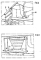
- FIG. 2 Figure 3 shows substantially the closed housing 18 of the discharge device 12 including the side wall 22 and, moreover, the pressure line or evacuation line 50.
- FIG. 3 shows the collecting funnel 14 after removal of the side wall 22 and the outer collecting area 19 and the collecting trough 20th
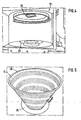
- FIG. 4 shows the discharge device 12 after removal of the collecting funnel 14 and in particular the upper Einpassvoriques 24 and the lower disc-shaped fitting device 26 for the collecting funnel 14th
- FIG. 5 shows the collecting funnel 14 with the upper fitting ring 28 and the lower disc-shaped fitting ring 29 for fitting the collecting funnel 14 in the housing 18 of the discharge device 12th
- FIG. 6 shows a cross section of the sieve-shaped collecting funnel 14 with regularly distributed around the circumference sieve openings 15 and the lower fitting ring 29,
- FIG. 7 shows in perspective above hinted the round housing of the discharge 12 and laterally offset, the liquid discharge 60 from the outer region of the discharge 12, wherein also initially a funnel is provided, and otherwise the structure in connection with FIG. 1 is shown in more detail.
- FIG. 8 shows a decentralized feed station 100 for supplying the input wet waste via cyclically open shut-off devices 32, 34 via the standing under vacuum or compressed air transport pipe 40 to the discharge 12.
- With 36 is a connection indicated by the vacuum / vacuum or compressed air for transport purposes, for ventilation purposes or may be supplied for cleaning, 31,33 represent common pipe connectors.
- the core of the feed station 100 consists of a collecting funnel 104, to which an outer sieve ring 102 adjoins, which rests easily removable on a continuous drainage channel 106, which can be connected via a drainage in the form of a connecting line 107 directly to a drain line of the room.
- the sieve ring 102 has an inclination angle or opening angle of 20 ° inwards and downwards, the collecting funnel delimiting below of preferably 50 ° to 60 ° to the horizontal.
- FIG. 9 shows another collecting funnel of the feeding station 100, consisting of an upper conical dividing funnel 104 'with an angle of about 40 ° to 50 ° and a subsequent lower funnel 105 of about 70 ° to 80 ° to the horizontal, which leads to the transport tube 40.
- FIG. 10 shows a perspective view of the feed station 100 with outer flat Siebring 102 and the steeper inwardly adjacent collecting funnel 104, which leads to the transport tube 40 or possibly first to another part funnel, intermediate tube, various shut-off devices, etc.
- FIG. 11 shows the representation of FIG. 10 with removed outer sieve 102 and visible below surrounding drainage channel 106, which has a drainage 107, which is preferably connected directly to the sewer pipe.
Landscapes
- Engineering & Computer Science (AREA)
- Mechanical Engineering (AREA)
- Processing Of Solid Wastes (AREA)
- Devices And Processes Conducted In The Presence Of Fluids And Solid Particles (AREA)
- Refuse Collection And Transfer (AREA)
- Filtration Of Liquid (AREA)
- Fertilizers (AREA)
- Separation Of Suspended Particles By Flocculating Agents (AREA)
- Treatment Of Sludge (AREA)
- Disintegrating Or Milling (AREA)
Description
- Die Erfindung bezieht sich auf eine Müllentsorgungsanlage für Nassmüll gemäß dem Oberbegriff des Anspruches 1.
- Derartige Müllentsorgungsanlagen werden in Großküchen aller Art, beispielsweise Betriebskantinen, eingesetzt.
- Eine derartige Müllentsorgungsanlage 1 ist im
DE-U- 299 17059 beschrieben. - Die
EP-B-0204879 beschreibt eine ähnliche Müllentsorgungsanlage mit einem siebartigen Auffangtrichter für den Nassmüll. - Der Erfindung liegt die Aufgabe zugrunde, eine Müllentsorgungsanlage so auszugestalten, dass der Flüssigkeitsanteil des Nassmülles im Festanteil des weiter zu verarbeitenden Nassmülles deutlich reduziert wird.
- Insbesondere sollen nach der Zufuhr des Nassmülls von dezentralen Aufgabestationen in eine zentrale Austragsvorrichtung innerhalb dieser Austragsvorrichtung Entwässerungseinrichtungen vorgesehen werden, bevor oder ohne dass der Nassmüll zerkleinert und/oder in nachgeschalteten Entwässerungspressen, wie Schneckenpressen, entwässert worden wäre.
- Die Aufgabe wird erfindungsgemäß durch die Merkmale des Anspruches 1 gelöst. Weitere Ausgestaltungen der Erfindung sind in den Unteransprüchen unter Schutz gestellt.
- Beim Schutzgegenstand ist im Gehäuse der Austragsvorrichtung ein siebartiger; konischer, als Sieb ausgebildeter vertikaler Auffangtrichter vorgesehen. Die Einströmung von Luft in die Austragsvorrichtung erfolgt tangential. Dadurch rotiert die Luft zusammen mit dem Nassmüll im Sieb-artigen vertikalen Auffangtrichter. Der entwässerte feste Müll fällt nach unten. In einem an den Auffangtrichter angrenzenden äusseren Auffangbereich des Gehäuses wird der Großteil der Flüssigkeit unmittelbar abgeführt, sei es infolge Druckluft von oben in den Auffangtrichter hinein, wobei die Druckluft von einem Druckluftkompressor geliefert wird, oder durch einen im Außenbereich des Auffangtrichters über eine Vakuumpumpe erzeugten Unterdruck, oder einfach durch Ablaufen der Flüssigkeit aufgrund der Schwerkraft.
- Der Transport des Nassmülls erfolgt portionsweise von den Aufgabestationen zur zentralen Austragsvorrichtung, gleichermaßen wird die aufgefangene Flüssigkeit vom Aussenbereich des Auffangtrichters, der vorzugsweise eine Auffangwanne aufweist, über eine Flüssigkeitsableitung und eine ventilgesteuerte Zwischenschleuse portionsweise in Intervallen abgesaugt und der Kanalisation oder dergleichen zugeführt.
- Ebenfalls in einzelnen Portionen, von Hand oder zyklisch gesteuert, wird der vorentwäserte Müll durch den offenen Boden des Auffangtrichters hindurch nach unten in eine Schleusenkammer abgeführt, die durch einen oberen und einen unteren Schieber gesteuert verschließbar und zu öffnen ist, und von da zu einer Leitung für die weitere Verarbeitung. Von da kann der Müll zu einer Zerkleinerungsanlage und/oder eine zusätzliche Rest-Entwässerungspresse wie eine Entwässerungsschnecke geführt werden, und von da in ein Speiserestsilo, wobei die austretende Restflüssigkeit über eine weitere Entwässerungsleitung der Kanalisation zugeführt werden kann.
- Der Auffangtrichter kann vorzugsweise über eine abgedichtete seitliche entfernbare Seitenwand der Austragsvorrichtung leicht ausgewechselt und wieder präzise justiert eingebaut sowie durch leicht lösbare Klemmen festgehalten werden. Im Auffangtrichter können Filter, Siebe oder Spaltfilter oder dergleichen angeordnet werden, um eine Feinabstimmung zum jeweiligen Nassmüll zu ermöglichen.
Sowohl der Auffangtrichter als auch die gesamte Kammer der Austragsvorrichtung können durch oben angeordnete Reinigungsdüsen in einfacher Weise, beispielsweise auch automatisch, gereinigt werden. - Die Aufgabestationen sind zweckmäßigerweise ebenfalls trichterförmig ausgebildet. Vorzugsweise weisen sie einen horizontalen oder flacheren äusseren Siebring, etwa mit einem Winkelbereich zwischen 15 und 25°, zur Horizontalen nach innen und unten zu, und einen nach innen anschließenden steileren Auffangtrichter mit einem Winkel von etwa 40 bis 65°, vorzugsweise 50 bis 60° in Bezug zur Horizontale auf. Bei einem bevorzugten Ausführungsbeispiel besteht der Auffangtrichter aus einem zur Horizontale flacheren oberen Trichterabschnitt mit einem Winkel von etwa 40 bis 50°, und einem daran anschließenden unteren Trichterabschnitt mit einem Winkel von etwa 70 bis 80° zur Horizontalen. Durch die Wahl dieser Winkel kann auf eine Nass-Spülvorrichtung verzichtet werden, der Nassmüll, wie er in Großküchen anfällt, fällt dadurch von selbst automatisch in das anschließende zentrale Transportrohr. Dieses wird in Intervallen geöffnet und, unter Unterdruck stehend, wird der angehäufte Nassmüll zur zentralen Austragsvorrichtung transportiert. Statt einer Vakuumanlage und Unterdruck ist auch eine Druckluftanlage einsetzbar, welche im Prinzip in gleicher Weise arbeitet, wobei der Nassmüll von den einzelnen Aufgabestationen in den oberen Bereich des Auffangtrichters der Austragsvorrichtung gedrückt wird.
- Der äussere obere Siebring liegt in einer Entwässerungsrinne leicht lösbar auf, die über eine Verbindungsleitung mit einer Abwasserleitung verbunden ist.
- Ausführungsbeispiele der Erfindung sind in der Zeichnung dargestellt. Es zeigt:
-
Figur 1 ein Gesamtschema einer Müllentsorgungsanlage für Nassmüll, -
Figur 2 eine perspektivische Ansicht auf eine geschlossene Austragsvorrichtung, -
Figur 3 die Ansicht vonFigur 2 mit abgenommener Seitenwand, wobei der Auffangtrichter im eingebauten Zustand sichtbar ist,Figur 4 einen Blick auf das Gehäuse der Austragsvorrichtung bei herausgenommenen Auffangtrichter, -
Figur 5 eine perspektivische Darstellung des herausgenommenen Auffangtrichters, -
Figur 6 einen Querschnitt durch den Auffangtrichter, -
Figur 7 eine perspektivische Ansicht auf untere Teile der Müllentsorgungsanlage, insbesondere die Ableitung der Entwässerungs-Flüssigkeit, -
Figur 8 eine Übersichtszeichnung einer Aufgabestation mit einem bestimmten Auffantrichter, -
Figur 9 einen Querschnitt durch einen anders gestalteten Auffangtrichter der Aufgabestation, -
Figur 10 eine perspektivische Draufsicht auf einen Auffangtrichter mit herausnehmbarem Siebring, -
Figur 11 die Darstellung vonFigur 10 mit teilweise herausgenommenen Siebring und sichtbarer Entwässerungsrinne mit Entwässerung. - In der Zeichnung sind gleiche Teile mit gleichen Bezugszeichen versehen. Die Müllentsorgungsanlage für Nassmüll in
Fig. 1 ist allgemein mit 10 bezeichnet, die Austragsvorrichtung allgemein mit 12, der Auffangtrichter allgemein mit 14. - Die Flüssigkeitsableitung ist allgemein mit 60 bezeichnet, die Austragsleitung für die entwässerten festen Teile mit 70, der nachfolgende Zerkleinerer mit 80, die daran anschließende Entwässerungspresse mit 90.
- Die Aufgabestation ist allgemein mit 30 bezeichnet, das Transportrohr von der Aufgabestation 30 zur Austragsvorrichtung 12 ist mit 40 bezeichnet, die Evakuierleitung oder Druckleitung zwischen Austragsvorrichtung 12 und Druckkompressor oder Vakuumpumpe 52 ist mit 50 bezeichnet, die Rückleitung der Transportluft zur Abluftleitung 53 ist mit 54 bezeichnet.
- Das Gehäuse der Austragsvorrichtung 12 ist mit 18 bezeichnet, der äussere Auffangbereich für Flüssigkeit desselben mit 19, die leicht lösbare Seitenwand mit 22, der offene Boden des Auffangtrichters 14 mit 16, die untere am Boden angeordnete Auffangwanne des Gehäuses 18 für die Flüssigkeit mit 20.
- Von der Auffangwanne 20 geht die allgemein mit 60 bezeichnete Flüssigkeitsableitung weg, die über ein oberes Steuerventil 64 und ein unteres Steuerventil 66 über eine Zwischen-Schleusenkammer 62 eine intervallmäßige Entwässerung in die Kanalisation etc. ermöglicht.
- Nach der steuerbaren zyklischen Entwässerung des von oben in den Auffangtrichter 14 gelangenden Nassmülls wird dieser zyklisch über eine an den offenen Boden 16 anschließende Austragsleitung 70 einem Speiserestesilo zugeführt, und zwar über den offenen Boden 16 des Auffangtrichters 14, einen oberen steuerbaren Schieber 74 und einen unteren steuerbaren Schieber 76, welche eine Schleusenkammer 72 steuern, nämlich öffnen und verschließen.
- Daran anschließend kann der weitgehend entwässerte Nassmüll einem Zerkleinerer 80, und von da einer üblichen Entwässerungspresse, hier in Form einer Schneckenpresse 90, zugeführt werden. Der nochmals getrocknete Müll geht dann über eine Leitung 94 in ein Speiserestesilo, wo er weiter verarbeitet beziehungsweise abgeführt wird. Aus der Entwässerungspresse 90 führt eine weitere Entwässerungsleitung 92 beispielsweise zum Abwasserkanal.
-
Figur 2 zeigt im wesentlichen das geschlossene Gehäuse 18 der Austragsvorrichtung 12 einschließlich der Seitenwand 22 und darüberhinaus die Druckleitung oder Evakuierleitung 50. -
Figur 3 zeigt den Auffangtrichter 14 nach Entfernung der Seitenwand 22 sowie den äusseren Auffangbereich 19 und die Auffangwanne 20. -
Figur 4 zeigt die Austragsvorrichtung 12 nach Entfernung des Auffangtrichters 14 und insbesondere die obere Einpassvorrichtung 24 sowie die untere scheibenförmige Einpassvorrichtung 26 für den Auffangtrichter 14. -
Figur 5 zeigt den Auffangtrichter 14 mit dem oberen Passring 28 und dem unteren scheibenförmigen Passring 29 für das Einpassen des Auffangtrichters 14 in das Gehäuse 18 der Austragsvorrichtung 12. -
Figur 6 zeigt einen Querschnitt des siebförmigen Auffangtrichters 14 mit regelmäßig um den Umfang verteilten Sieböffnungen 15 und den unteren Passring 29, -
Figur 7 zeigt perspektivisch oben andeutungsweise das runde Gehäuse der Austragsvorrichtung 12 und darunter seitlich versetzt, die Flüssigkeitsableitung 60 aus dem Aussenbereich der Austragsvorrichtung 12, wobei ebenfalls zunächst ein Trichter vorgesehen ist, und im übrigen der Aufbau in Zusammenhang mitFigur 1 etwas näher dargestellt ist. -
Figur 8 zeigt eine dezentrale Aufgabestation 100 zur Zufuhr des eingegebenen Nassmülls über zyklisch zu öffnende Absperreinrichtungen 32, 34 über das unter Vakuum oder Druckluft stehende Transportrohr 40 zur Austragsvorrichtung 12. Mit 36 ist ein Anschluss angedeutet, von dem Unterdruck/Vakuum oder Druckluft zu Transportzwecken, zu Lüftungszwecken oder zu Reinigungszwecken zugeführt werden kann, 31,33 stellen übliche Rohrverbinder dar. - Das Kernstück der Aufgabestation 100 besteht aus einem Auffangtrichter 104, an den ein äusserer Siebring 102 angrenzt, der leicht abnehmbar auf einer umlaufenden Entwässerungsrinne 106 aufliegt, welche über eine Entwässerung in Form einer Verbindungsleitung 107 direkt mit einer Abflussleitung des Raumes verbunden sein kann. Der Siebring 102 hat nach innen und unten einen Neigungswinkel oder Öffnungswinkel von 20°, der unten abgrenzende Auffangtrichter von vorzugsweise 50° bis 60° zur Horizontalen.
-
Figur 9 zeigt einen anderen Auffangtrichter der Aufgabestation 100, bestehend aus einem oberen konischen Teiltrichter 104' mit einem Winkel von etwa 40° bis 50° und einem anschließenden unteren Teiltrichter 105 von etwa 70° bis 80° zur Horizontalen, der zum Transportrohr 40 führt. -
Figur 10 zeigt in perspektivischer Darstellung den Aufgabestation 100 mit äusserem flachen Siebring 102 und dem steileren nach innen anschließenden Auffangtrichter 104, der zum Transportrohr 40 oder gegebenenfalls zunächst zu einem weiteren Teiltrichter, Zwischenrohr, diversen Absperrvorrichtungen etc. führt. -
Figur 11 zeigt die Darstellung vonFigur 10 mit entferntem äusseren Siebring 102 und darunter sichtbarer umlaufender Entwässerungsrinne 106, die eine Entwässerung 107 aufweist, die vorzugsweise direkt mit der Abwasserleitung verbunden ist.
Claims (13)
- Müllentsorgungsanlage (10) für Nassmüll, insbesondere für Abfälle von Großküchen,
mit einer zentralen Austragsvorrichtung (12),
Aufgabestationen (30,100) zur steuerbaren portionsweisen Zuführung von Nassmüll zur Austragsvorrichtung (12) über Transportrohre (40) und einem Transportlufterzeuger in Form eines Druckluftkompressors oder einer Vakuumpumpe (52) zum Transportieren des Nassmülls zur zentralen Austragsvorrichtung (12), gekennzeichnet durch einen siebartigen konischen, als Sieb ausgebildeten vertikalen Auffangtrichter (14) im Gehäuse (18) der Austragsvorrichtung (12), in den der gesamte Nassmüll von den einzelnen Aufgabestationen (30,100) in den oberen Bereich des Auffangtrichters (14) gedrückt wird, einen an den Auffangtrichter (14) angrenzenden äußeren Auffangbereich (19) des Gehäuses (18) für die durch den Auffangtrichter (14) hindurch nach außen tretende Flüssigkeit, und eine an den offenen Boden (16) des Auffangtrichters (14) anschließende Austragsleitung für die entwässerten festen Teile, die mit einer Schleusenkammer (72) in Verbindung steht, welche durch einen oberen steuerbaren Schieber (74) und einen unteren steuerbaren Schieber (76) zu öffnen und zu verschließen ist, wobei die Schleusenkammer (72) mit einer Leitung zur weiteren Müllentsorgung verbunden ist. - Müllentsorgungsanlage (10) nach Anspruch 1, dadurch gekennzeichnet, dass der äussere Auffangbereich (19) für die aus dem Auffangtrichter (14) seitlich nach aussen tretende Flüssigkeit durch das Gehäuse (18) der Austragsvorrichtung (12) und eine untere Auffangwanne (20) gebildet ist, an welcher die Flüssigkeitsableitung (60) angeordnet ist.
- Müllentsorgungsanlage (10) nach einem der Ansprüche 1 oder 2, gekennzeichnet durch eine leicht zu öffnende, abdichtende Seitenwand (22) für das Gehäuse (18) der Austragsvorrichtung (12) zum leichten Aus- und Einbringen des Auffangtrichters (14),- je eine obere (24) und eine untere (26) Einpassvorrichtung an der oberen Wand beziehungsweise dem Boden des Gehäuses (18) für eine präzise Anpassung des oberen Passringes (28) beziehungsweise des unteren Passringes (29) des Auffangtrichters (12).
- Müllentsorgungsanlage (10) nach einem der Ansprüche 1 bis 3, dadurch gekennzeichnet, dass der eingebaute Auffangtrichter (14) durch Klemmvorrichtungen gesichert ist, die ohne Werkzeug von Hand leicht lösbar sind.
- Müllentsorgungsanlage (10) nach einem der Ansprüche 1 bis 4, dadurch gekennzeichnet, dass im Auffangtrichter (14) Filter, Wechselsiebe, Spaltfilter oder dergleichen angeordnet sind.
- Müllentsorgungsanlage (10) nach einem der Ansprüche 1 bis 5, dadurch gekennzeichnet, dass die im äußeren Auffangbereich (19) des Auffangtrichters (14) gesammelte Flüssigkeit über die Flüssigkeitsableitung (60) in steuerbaren Intervallen durch Schwerkraft abläuft, vorzugsweise über eine zwischen zwei Steuerventilen (64, 66) angeordnete Zwischenschleuse (62).
- Müllentsorgungsanlage (10) nach einem der Ansprüche 1 bis 6, gekennzeichnet durch steuerbare obere Reinigungsdüsen am Gehäuse (18) der Austragsvorrichtung (12) für den Auffangtrichter (14) und das gesamte Gehäuse (18).
- Müllentsorgungsanlage (10) nach einem der Ansprüche 1 bis 7, dadurch gekennzeichnet, dass eine tangentiale Einströmung von Luft in die zentrale Austragsvorrichtung (12) vorgesehen ist, derart, dass die Luft zusammen mit dem Nassmüll im siebartigen vertikalen Auffangtrichter (14) rotiert.
- Müllentsorgungsanlage (10) nach Anspruch 8, dadurch gekennzeichnet, dass die Schleusenkammer (72) mit einem Zerkleinerer (80) des weitgehend vorentwässerten Mülls verbunden ist, von welcher er über eine Entwässerungspresse (90) geleitet werden kann, um zu einem Speiserestesilo (94) oder dergleichen abgeführt zu werden, wobei die Restflüssigkeit über eine weitere Entwässerungsleitung (92) der Kanalisation zugeführt werden kann.
- Müllentsorgungsanlage (10) nach einem der Ansprüche 1 bis 9, dadurch gekennzeichnet, dass die Aufgabestation (100) im wesentlichen aus einem konischen Auffangtrichter (104; 104', 105) besteht, an dessen oberen Rand ein äusserer flacher Siebring (102) angrenzt, und wobei der Aufgabetrichter (104; 104', 105) unten in das Transportrohr (40) für den Nassmüll führt.
- Müllentsorgungsanlage (10) nach Anspruch 10, dadurch gekennzeichnet, dass der äussere flache Siebring (102) auf einer Entwässerungsrinne (106) leicht herausnehmbar gehaltert ist beziehungsweise aufliegt, die eine Verbindungsleitung (107) zur Abwasserleitung des Raumes oder dergleichen aufweist.
- Müllentsorgungsanlage (10) nach Anspruch 11, dadurch gekennzeichnet, dass der äussere flache Siebring (102) horizontal angeordnet ist, oder einen Öffnungswinkel von 15° bis 25°, vorzugsweise 20°, zur Horizontale nach innen zu aufweist, und dass der Öffnungswinkel des Auffangtrichters (104) nach innen zu 40° bis 65°, vorzugsweise 50° bis 60°, zur Horizontale beträgt,
derart, dass ein Einfüllen ohne Zugabe von Wasser und ohne Verstopfungsgefahr durch Brückenbildung von größeren Speiseresten, Gemüse etc. ermöglicht wird. - Müllentsorgungsanlage (10) nach Anspruch 11, dadurch gekennzeichnet, dass der Auffangtrichter aus einem flacheren oberen Teiltrichter (104') von etwa 40° bis 50° und einem angrenzenden unteren Teiltrichter (105) von etwa 70° bis 80° Öffnungswinkel zur Horizontalen besteht.
Applications Claiming Priority (2)
| Application Number | Priority Date | Filing Date | Title |
|---|---|---|---|
| DE20106954U DE20106954U1 (de) | 2001-04-23 | 2001-04-23 | Müllentsorgungsanlage für Nassmüll, insbesondere für Abfälle von Großküchen |
| DE20106954U | 2001-04-23 |
Publications (2)
| Publication Number | Publication Date |
|---|---|
| EP1253094A1 EP1253094A1 (de) | 2002-10-30 |
| EP1253094B1 true EP1253094B1 (de) | 2008-10-15 |
Family
ID=7956072
Family Applications (1)
| Application Number | Title | Priority Date | Filing Date |
|---|---|---|---|
| EP02009060A Expired - Lifetime EP1253094B1 (de) | 2001-04-23 | 2002-04-23 | Müllentsorgungsanlage für Nassmüll, insbesondere für Abfälle von Grossküchen |
Country Status (6)
| Country | Link |
|---|---|
| US (1) | US7025882B2 (de) |
| EP (1) | EP1253094B1 (de) |
| JP (1) | JP2004519328A (de) |
| AT (1) | ATE411245T1 (de) |
| DE (2) | DE20106954U1 (de) |
| WO (1) | WO2002085759A2 (de) |
Cited By (1)
| Publication number | Priority date | Publication date | Assignee | Title |
|---|---|---|---|---|
| CN107539784A (zh) * | 2017-08-25 | 2018-01-05 | 中国城市建设研究院有限公司 | 一种餐厨垃圾的气体输送系统和方法 |
Families Citing this family (11)
| Publication number | Priority date | Publication date | Assignee | Title |
|---|---|---|---|---|
| DE20106954U1 (de) * | 2001-04-23 | 2001-10-25 | MEIKO Maschinenbau GmbH & Co., 77652 Offenburg | Müllentsorgungsanlage für Nassmüll, insbesondere für Abfälle von Großküchen |
| US20080288786A1 (en) * | 2004-12-20 | 2008-11-20 | Michael Stephen Fiske | System with access keys |
| KR101203878B1 (ko) * | 2005-01-27 | 2012-11-23 | 엔박 에이비 | 쓰레기의 탈수 시스템 및 방법 |
| JP5147960B2 (ja) * | 2011-02-23 | 2013-02-20 | 三建設備工業株式会社 | 攪拌分離槽 |
| DE102014207411A1 (de) | 2014-04-17 | 2015-11-05 | Meiko Maschinenbau Gmbh & Co. Kg | Entsorgungsvorrichtung, Entsorgungssystem und Verfahren zur Entsorgung von Speiseresten |
| CN104555436B (zh) * | 2014-12-31 | 2017-09-22 | 青岛东方循环能源有限公司 | 远距离输送和除湿生活垃圾的方法及装置 |
| CN105129286B (zh) * | 2015-08-24 | 2017-04-19 | 浙江省海洋水产研究所 | 实验室垃圾存放桶及处理方法 |
| CN111167206A (zh) * | 2020-01-06 | 2020-05-19 | 王�华 | 一种新型污水处理用格栅除污机 |
| CN112090525B (zh) * | 2020-09-16 | 2021-07-09 | 山西龙鼎沅重工装备有限公司 | 一种间歇输料的煤矿破碎筛选设备 |
| CN113091864A (zh) * | 2021-05-11 | 2021-07-09 | 洛阳金鼎企业管理咨询有限公司 | 一种用于餐厨垃圾处理的分类称重物联网监管系统及方法 |
| CN114101273B (zh) * | 2021-11-12 | 2023-01-17 | 武汉博瑞世纪园林景观工程有限公司 | 一种建筑垃圾的回收加工处理方法 |
Family Cites Families (5)
| Publication number | Priority date | Publication date | Assignee | Title |
|---|---|---|---|---|
| US3317047A (en) * | 1964-11-05 | 1967-05-02 | Hansen Roy Dahl | Sewage disposal system |
| ATE48402T1 (de) * | 1985-06-14 | 1989-12-15 | Braendle Ag Metallbau | Einrichtung zur aufnahme von abfallgut. |
| SE9401529L (sv) | 1994-05-04 | 1995-11-05 | Centralsug Svs Ab | Vakuumackumulator ansluten till en sugledning och anordning för avvattning och borttransport av sopor medelst vakuum |
| DE29917059U1 (de) | 1999-09-28 | 2001-01-25 | Wagner, Thomas, 63599 Biebergemünd | Förder- und Zerkleinerungsanlage für Küchenabfälle |
| DE20106954U1 (de) | 2001-04-23 | 2001-10-25 | MEIKO Maschinenbau GmbH & Co., 77652 Offenburg | Müllentsorgungsanlage für Nassmüll, insbesondere für Abfälle von Großküchen |
-
2001
- 2001-04-23 DE DE20106954U patent/DE20106954U1/de not_active Expired - Lifetime
-
2002
- 2002-04-23 EP EP02009060A patent/EP1253094B1/de not_active Expired - Lifetime
- 2002-04-23 JP JP2002583298A patent/JP2004519328A/ja active Pending
- 2002-04-23 US US10/257,089 patent/US7025882B2/en not_active Expired - Fee Related
- 2002-04-23 WO PCT/EP2002/004463 patent/WO2002085759A2/de not_active Ceased
- 2002-04-23 AT AT02009060T patent/ATE411245T1/de not_active IP Right Cessation
- 2002-04-23 DE DE50212885T patent/DE50212885D1/de not_active Expired - Lifetime
Cited By (1)
| Publication number | Priority date | Publication date | Assignee | Title |
|---|---|---|---|---|
| CN107539784A (zh) * | 2017-08-25 | 2018-01-05 | 中国城市建设研究院有限公司 | 一种餐厨垃圾的气体输送系统和方法 |
Also Published As
| Publication number | Publication date |
|---|---|
| ATE411245T1 (de) | 2008-10-15 |
| EP1253094A1 (de) | 2002-10-30 |
| JP2004519328A (ja) | 2004-07-02 |
| US7025882B2 (en) | 2006-04-11 |
| DE20106954U1 (de) | 2001-10-25 |
| US20030201220A1 (en) | 2003-10-30 |
| WO2002085759A2 (de) | 2002-10-31 |
| WO2002085759A3 (de) | 2003-02-06 |
| DE50212885D1 (de) | 2008-11-27 |
Similar Documents
| Publication | Publication Date | Title |
|---|---|---|
| AT505299B1 (de) | Vorrichtung zum trocknen und reinigen von kleinstückigem gut | |
| EP0040425B1 (de) | Vorrichtung zum Entfernen von Schwemmgut und Feststoffen aus Zulaufgerinnen, insbesondere von Kläranlagen | |
| EP1253094A1 (de) | Müllentsorgungsanlage für Nassmüll, insbesondere für Abfälle von Grossküchen | |
| DE2600161A1 (de) | Anordnung zum beseitigen von abfaellen | |
| DE4005331A1 (de) | Abfallaufbereitungsanlage | |
| DE3411918C2 (de) | ||
| EP0778790A1 (de) | Vorrichtung zum entfernen von abscheidegut aus in einem gerinne strömender flüssigkeit | |
| EP2875942A1 (de) | Vorrichtung und Verfahren zum Eindicken von flüssigem feststoffhaltigem Substrat | |
| EP0827768A1 (de) | Vorrichtung und Verfahren zum Filtern von Suspensionen | |
| DE10250053A1 (de) | Vorrichtung zur Verdichtung und Entwässerung von hygienisch bedenklichem Abfall, insbesondere Krankenhausabfall | |
| DE19523842C2 (de) | Abfallbeseitigungsvorrichtung, insbesondere zur Beseitigung von biologisch abbaubaren Küchen- und Haushaltsabfällen | |
| EP2320186B1 (de) | Vorrichtung zum Reinigen und Trocknen von kleinstückigem Gut, insbesondere von zerkleinerten Kunststoffabfällen | |
| DE2521120A1 (de) | Verfahren zum selbsttaetigen sammeln und foerdern von haus- oder industrie-abfaellen und vorrichtung zur durchfuehrung dieses verfahrens | |
| DE69532388T2 (de) | Mit einem Saugrohr verbundener Vakuumspeicher | |
| EP3623735B1 (de) | Recycling-vorrichtung | |
| DE10205064A1 (de) | Leichtstoffabscheider für Bauschutt | |
| EP1375002A1 (de) | Dokumentenvernichter, insbesondere für eine Absauganlage | |
| DE60002149T2 (de) | Vorrichtung und Verfahren zum Zerkleinern von Speiseresten | |
| DE3249687C2 (en) | Apparatus and process for separating off and drying solid substances from liquids | |
| WO2025180814A1 (de) | Kompostiervorrichtung | |
| WO1993008935A1 (de) | Vorrichtung und verfahren zur aufbereitung von flüssigkeit enthaltenden, zerkleinerbaren abfällen | |
| DE19640503C1 (de) | Verfahren und Vorrichtung zur Gewinnung von Sekundärspänen und -fasern | |
| DE3723657C2 (de) | ||
| DE9406712U1 (de) | Vorrichtung zum Entgraten und Entstauben von Tabletten | |
| DE3515536A1 (de) | Verfahren und vorrichtung fuer die aufbereitung von kunststoffabfaellen |
Legal Events
| Date | Code | Title | Description |
|---|---|---|---|
| PUAI | Public reference made under article 153(3) epc to a published international application that has entered the european phase |
Free format text: ORIGINAL CODE: 0009012 |
|
| AK | Designated contracting states |
Kind code of ref document: A1 Designated state(s): AT BE CH CY DE DK ES FI FR GB GR IE IT LI LU MC NL PT SE TR |
|
| AX | Request for extension of the european patent |
Free format text: AL;LT;LV;MK;RO;SI |
|
| 17P | Request for examination filed |
Effective date: 20030415 |
|
| AKX | Designation fees paid |
Designated state(s): AT BE CH CY DE DK ES FI FR GB GR IE IT LI LU MC NL PT SE TR |
|
| 17Q | First examination report despatched |
Effective date: 20060327 |
|
| GRAP | Despatch of communication of intention to grant a patent |
Free format text: ORIGINAL CODE: EPIDOSNIGR1 |
|
| GRAS | Grant fee paid |
Free format text: ORIGINAL CODE: EPIDOSNIGR3 |
|
| GRAA | (expected) grant |
Free format text: ORIGINAL CODE: 0009210 |
|
| AK | Designated contracting states |
Kind code of ref document: B1 Designated state(s): AT BE CH CY DE DK ES FI FR GB GR IE IT LI LU MC NL PT SE TR |
|
| REG | Reference to a national code |
Ref country code: GB Ref legal event code: FG4D Free format text: NOT ENGLISH Ref country code: CH Ref legal event code: EP |
|
| REG | Reference to a national code |
Ref country code: IE Ref legal event code: FG4D Free format text: LANGUAGE OF EP DOCUMENT: GERMAN |
|
| REF | Corresponds to: |
Ref document number: 50212885 Country of ref document: DE Date of ref document: 20081127 Kind code of ref document: P |
|
| NLV1 | Nl: lapsed or annulled due to failure to fulfill the requirements of art. 29p and 29m of the patents act | ||
| PG25 | Lapsed in a contracting state [announced via postgrant information from national office to epo] |
Ref country code: ES Free format text: LAPSE BECAUSE OF FAILURE TO SUBMIT A TRANSLATION OF THE DESCRIPTION OR TO PAY THE FEE WITHIN THE PRESCRIBED TIME-LIMIT Effective date: 20090126 |
|
| PG25 | Lapsed in a contracting state [announced via postgrant information from national office to epo] |
Ref country code: NL Free format text: LAPSE BECAUSE OF FAILURE TO SUBMIT A TRANSLATION OF THE DESCRIPTION OR TO PAY THE FEE WITHIN THE PRESCRIBED TIME-LIMIT Effective date: 20081015 Ref country code: FI Free format text: LAPSE BECAUSE OF FAILURE TO SUBMIT A TRANSLATION OF THE DESCRIPTION OR TO PAY THE FEE WITHIN THE PRESCRIBED TIME-LIMIT Effective date: 20081015 Ref country code: PT Free format text: LAPSE BECAUSE OF FAILURE TO SUBMIT A TRANSLATION OF THE DESCRIPTION OR TO PAY THE FEE WITHIN THE PRESCRIBED TIME-LIMIT Effective date: 20090316 |
|
| REG | Reference to a national code |
Ref country code: IE Ref legal event code: FD4D |
|
| PG25 | Lapsed in a contracting state [announced via postgrant information from national office to epo] |
Ref country code: DK Free format text: LAPSE BECAUSE OF FAILURE TO SUBMIT A TRANSLATION OF THE DESCRIPTION OR TO PAY THE FEE WITHIN THE PRESCRIBED TIME-LIMIT Effective date: 20081015 Ref country code: IE Free format text: LAPSE BECAUSE OF FAILURE TO SUBMIT A TRANSLATION OF THE DESCRIPTION OR TO PAY THE FEE WITHIN THE PRESCRIBED TIME-LIMIT Effective date: 20081015 |
|
| PLBE | No opposition filed within time limit |
Free format text: ORIGINAL CODE: 0009261 |
|
| STAA | Information on the status of an ep patent application or granted ep patent |
Free format text: STATUS: NO OPPOSITION FILED WITHIN TIME LIMIT |
|
| PG25 | Lapsed in a contracting state [announced via postgrant information from national office to epo] |
Ref country code: SE Free format text: LAPSE BECAUSE OF FAILURE TO SUBMIT A TRANSLATION OF THE DESCRIPTION OR TO PAY THE FEE WITHIN THE PRESCRIBED TIME-LIMIT Effective date: 20090115 |
|
| 26N | No opposition filed |
Effective date: 20090716 |
|
| BERE | Be: lapsed |
Owner name: MEIKO MASCHINENBAU G.M.B.H. & CO. Effective date: 20090430 |
|
| REG | Reference to a national code |
Ref country code: CH Ref legal event code: PL |
|
| PG25 | Lapsed in a contracting state [announced via postgrant information from national office to epo] |
Ref country code: CH Free format text: LAPSE BECAUSE OF NON-PAYMENT OF DUE FEES Effective date: 20090430 Ref country code: LI Free format text: LAPSE BECAUSE OF NON-PAYMENT OF DUE FEES Effective date: 20090430 |
|
| PG25 | Lapsed in a contracting state [announced via postgrant information from national office to epo] |
Ref country code: MC Free format text: LAPSE BECAUSE OF NON-PAYMENT OF DUE FEES Effective date: 20090430 |
|
| PG25 | Lapsed in a contracting state [announced via postgrant information from national office to epo] |
Ref country code: BE Free format text: LAPSE BECAUSE OF NON-PAYMENT OF DUE FEES Effective date: 20090430 |
|
| PG25 | Lapsed in a contracting state [announced via postgrant information from national office to epo] |
Ref country code: AT Free format text: LAPSE BECAUSE OF NON-PAYMENT OF DUE FEES Effective date: 20090423 |
|
| PG25 | Lapsed in a contracting state [announced via postgrant information from national office to epo] |
Ref country code: GR Free format text: LAPSE BECAUSE OF FAILURE TO SUBMIT A TRANSLATION OF THE DESCRIPTION OR TO PAY THE FEE WITHIN THE PRESCRIBED TIME-LIMIT Effective date: 20090116 |
|
| PG25 | Lapsed in a contracting state [announced via postgrant information from national office to epo] |
Ref country code: LU Free format text: LAPSE BECAUSE OF NON-PAYMENT OF DUE FEES Effective date: 20090423 |
|
| PG25 | Lapsed in a contracting state [announced via postgrant information from national office to epo] |
Ref country code: TR Free format text: LAPSE BECAUSE OF FAILURE TO SUBMIT A TRANSLATION OF THE DESCRIPTION OR TO PAY THE FEE WITHIN THE PRESCRIBED TIME-LIMIT Effective date: 20081015 |
|
| PG25 | Lapsed in a contracting state [announced via postgrant information from national office to epo] |
Ref country code: CY Free format text: LAPSE BECAUSE OF FAILURE TO SUBMIT A TRANSLATION OF THE DESCRIPTION OR TO PAY THE FEE WITHIN THE PRESCRIBED TIME-LIMIT Effective date: 20081015 |
|
| REG | Reference to a national code |
Ref country code: DE Ref legal event code: R082 Ref document number: 50212885 Country of ref document: DE Representative=s name: BOEHMERT & BOEHMERT, DE Ref country code: DE Ref legal event code: R082 Ref document number: 50212885 Country of ref document: DE Representative=s name: BOEHMERT & BOEHMERT ANWALTSPARTNERSCHAFT MBB -, DE |
|
| PGFP | Annual fee paid to national office [announced via postgrant information from national office to epo] |
Ref country code: GB Payment date: 20140423 Year of fee payment: 13 |
|
| PGFP | Annual fee paid to national office [announced via postgrant information from national office to epo] |
Ref country code: IT Payment date: 20140428 Year of fee payment: 13 Ref country code: FR Payment date: 20140416 Year of fee payment: 13 Ref country code: DE Payment date: 20140430 Year of fee payment: 13 |
|
| REG | Reference to a national code |
Ref country code: DE Ref legal event code: R119 Ref document number: 50212885 Country of ref document: DE |
|
| GBPC | Gb: european patent ceased through non-payment of renewal fee |
Effective date: 20150423 |
|
| PG25 | Lapsed in a contracting state [announced via postgrant information from national office to epo] |
Ref country code: GB Free format text: LAPSE BECAUSE OF NON-PAYMENT OF DUE FEES Effective date: 20150423 Ref country code: DE Free format text: LAPSE BECAUSE OF NON-PAYMENT OF DUE FEES Effective date: 20151103 Ref country code: IT Free format text: LAPSE BECAUSE OF NON-PAYMENT OF DUE FEES Effective date: 20150423 |
|
| REG | Reference to a national code |
Ref country code: FR Ref legal event code: ST Effective date: 20151231 |
|
| PG25 | Lapsed in a contracting state [announced via postgrant information from national office to epo] |
Ref country code: FR Free format text: LAPSE BECAUSE OF NON-PAYMENT OF DUE FEES Effective date: 20150430 |