EP1249372B1 - Halter für ein Bauteil mit geringen Abmessungen an einem Stossfänger - Google Patents
Halter für ein Bauteil mit geringen Abmessungen an einem Stossfänger Download PDFInfo
- Publication number
- EP1249372B1 EP1249372B1 EP02006850A EP02006850A EP1249372B1 EP 1249372 B1 EP1249372 B1 EP 1249372B1 EP 02006850 A EP02006850 A EP 02006850A EP 02006850 A EP02006850 A EP 02006850A EP 1249372 B1 EP1249372 B1 EP 1249372B1
- Authority
- EP
- European Patent Office
- Prior art keywords
- bumper
- holder
- tongues
- component
- piece
- Prior art date
- Legal status (The legal status is an assumption and is not a legal conclusion. Google has not performed a legal analysis and makes no representation as to the accuracy of the status listed.)
- Expired - Lifetime
Links
Images

Classifications
-
- B—PERFORMING OPERATIONS; TRANSPORTING
- B60—VEHICLES IN GENERAL
- B60R—VEHICLES, VEHICLE FITTINGS, OR VEHICLE PARTS, NOT OTHERWISE PROVIDED FOR
- B60R19/00—Wheel guards; Radiator guards, e.g. grilles; Obstruction removers; Fittings damping bouncing force in collisions
- B60R19/02—Bumpers, i.e. impact receiving or absorbing members for protecting vehicles or fending off blows from other vehicles or objects
- B60R19/48—Bumpers, i.e. impact receiving or absorbing members for protecting vehicles or fending off blows from other vehicles or objects combined with, or convertible into, other devices or objects, e.g. bumpers combined with road brushes, bumpers convertible into beds
- B60R19/483—Bumpers, i.e. impact receiving or absorbing members for protecting vehicles or fending off blows from other vehicles or objects combined with, or convertible into, other devices or objects, e.g. bumpers combined with road brushes, bumpers convertible into beds with obstacle sensors of electric or electronic type
Definitions
- the invention relates to a holder for a component of small dimensions on a bumper of a motor vehicle according to the preamble of the first claim.
- Automotive bumpers are increasingly being used nowadays to support components of small dimensions in which the position on a bumper due to the exposed position is particularly advantageous for their function. So it is known, for example, turn signals, lights and especially distance sensors (Parktronic sensors, abbreviated PTS), which determine the distance to other vehicles or obstacles and are intended as parking aids to install in the bumper of motor vehicles.
- PTS distance sensors
- Under bumper is to be understood both a one-piece, and one composed of modules bumper, in which the components are each inserted in a module of the bumper. The components must be fastened in such a way that it is not possible to loosen or even fall out if they impact the bumpers, in particular due to impact loads.
- an inventive holder has a very simple structure.
- the holder consists in its essential components of two tongues, which are each connected via a foot fixed to the bumper or, in a modular construction of a bumper, with one of its modules. These tongues are elastic and perpendicular to the surface of the bumper at the opening which receives the component.
- the tongues can be molded simultaneously with the shaping of the entire bumper or, in the case of a modular construction, of a module of the bumper. Because the holder is integrally integrated in the bumper, eliminates a previously required additional part and its pre-assembly.
- the connection of the component with the tongues is advantageously carried out detachably by means of a clip connection, wherein nose-shaped projections engage in recesses or undercuts in a known manner.
- the tongues of the holder are connected to one another on at least one side of the opening for receiving the component in its foot region by a web, which has substantially the outer contour of the male component.
- This bar makes the holder stable, holds the component in its position and facilitates its installation by the possible lateral guidance when inserted into the holder.
- the holder is given particular stability when the bridge is connected to the module or the bumper via a thin wall.
- the web between the two tongues can also be separated by a gap from the bumper or the module of the bumper, which is a more elastic Execution yields Spraying and molding of the holder is also simplified, especially when the surface of the bumper or the module is curved.
- At least one of the tongues is elastically connected to the web, the insertion of the component in the holder and the possible re-release is facilitated.
- the elasticity can be achieved by having a notch between tongue and web.
- FIG. 1 is a module of a bumper not fully illustrated here.
- Fastening means 2 in the form of locking lugs on the edge 3 of the module 1 allow clipping into the basic structure of the bumper.
- the mold 4 of the module 1 is curved.
- An inventive holder 5 on the inside of the module 1 takes in the present embodiment, a distance sensor 25, a PTS, on, as shown in Figure 3.
- the distance sensor 25 looks through a circular opening 6 in the module 1, the cover 26 of the sensor opening with the outer contour 4 of the module 1 closes. The opening 6 is almost completely covered in the figure 1 by the holder 5.
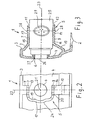
- the main features of the holder 5 are the two tongues 7 and 8. With their feet 9 and 10, they are molded onto the module 1. For better insertion of the distance sensor their free tongue ends, 11 on the tongue 7 and 12 on the tongue 8, bevelled. A recess 13 on the tongue 7 and 14 on the tongue 8 serves in each case to receive the nose-shaped projections 28 on the housing of the distance sensor 25 and thus to produce a clip connection, as shown in FIG.
- the foot region 15 of the tongue 7 and the foot region 16 of the tongue 8 are connected by means of a web 17, which essentially has the contour of the distance sensor to be held.
- the web 17 is separated in the present embodiment by a gap 18 of the curved surface 4 of the module 1, whereby the injection with the module facilitates and the elastic behavior of the holder is improved.
- the web 17 may be connected by a thin wall to the curved surface 4 of the module or the bumper 1.
- the upper edge 19 of the web 17 is facing inwards, that is beveled towards the opening, to facilitate the insertion of the distance sensor.
- the tongue 8 is elastically coupled to the web 17. Starting from the upper edge 19 of the web 17, a notch 20 extends between the tongue 8 and the web 17 to about two thirds of the height of the web. This makes it possible that when inserting the distance sensor in the holder 5, the tongue 8 can retreat unhindered from the web 17.
- the holder 5 is made of a plastic which has a certain elasticity and thus allows the spring-back of the tongues 7 and in particular of the tongue 8 during the production of the clip connection, without the tongues breaking off as a result.
- FIG. 2 shows a plan view of the rear side of the module 1 in the region of the holder 5.
- the symmetry lines 22 and 23 Through the center 21 of the opening 6 extend at right angles to each other, the symmetry lines 22 and 23. About the feet 9 and 10, which the Symmetry line 22 intersects, the holder 5 is connected to the module. The two tongues 7 and 8 are located on the symmetry line 22 opposite.
- the web 17 encloses the opening 6, wherein the bulge 24 corresponds to the contour of the male distance sensor.
- the view in Figure 3 corresponds to a section in the plane along the line of symmetry 22.
- the distance sensor 25 inserted into the holder 5, shown.
- the distance sensor 25 extends with its sensor opening
- the cover 26 terminates with the surface of the module 1, through the opening 6 and is supported via a ring 27 made of an elastic material on the edge of the opening 6 from.
- the tongues 7 and 8 abut against the outer contour of the distance sensor 25.
- the nose-shaped projections 28 on the housing of the distance sensor 25 engage in the recess 13 of the tongue 7 and the recess 14 of the tongue 8 and thus fix the distance sensor 25 in the holder 5.
- the connector 29 for connecting the signal line to the not here illustrated electronic circuit of the sensor.
Landscapes
- Engineering & Computer Science (AREA)
- Mechanical Engineering (AREA)
- Measurement Of Velocity Or Position Using Acoustic Or Ultrasonic Waves (AREA)
- Fittings On The Vehicle Exterior For Carrying Loads, And Devices For Holding Or Mounting Articles (AREA)
- Lighting Device Outwards From Vehicle And Optical Signal (AREA)
- Snaps, Bayonet Connections, Set Pins, And Snap Rings (AREA)
- Vehicle Step Arrangements And Article Storage (AREA)
- Details Of Measuring And Other Instruments (AREA)
Description
- Die Erfindung betrifft einen Halter für ein Bauteil mit geringen Abmessungen an einem Stoßfänger eines Kraftfahrzeugs entsprechend dem Oberbegriff des ersten Anspruchs.
- Stoßfänger von Kraftfahrzeugen werden heutzutage in zunehmendem Maße dazu genutzt, Bauteile geringer Abmessungen zu tragen, bei denen die Position an einem Stoßfänger aufgrund der exponierten Lage für ihre Funktion besonders vorteilhaft ist. So ist es beispielsweise bekannt, Blinker, Begrenzungsleuchten und insbesondere Abstandssensoren (Parktronic-Sensoren, abgekürzt PTS), die den Abstand zu anderen Fahrzeugen oder Hindernissen feststellen und als Einparkhilfen gedacht sind, in die Stoßfänger von Kraftfahrzeugen einzubauen. Unter Stoßfänger ist sowohl ein einteiliger, als auch ein aus Modulen zusammengesetzter Stoßfänger zu verstehen, bei dem die Bauteile jeweils in einem Modul des Stoßfängers eingesetzt sind. Die Befestigung der Bauteile muss so erfolgen, dass bei Einwirkungen auf die Stoßfänger, insbesondere durch stoßartige Belastungen, eine Lockerung oder gar ein Herausfallen unmöglich ist.
- Es ist beispielsweise bei Abstandssensoren bekannt, diese zunächst in ein Vorgehäuse einzuschieben und dort in eine Clip-Verbindung einzuclipsen um sie dann mittels dieses Vorgehäuses in die dafür vorgesehene Aufnahme des Stoßfängers einzuclipsen , siehe z.b DE 19819698 A1. Diese Aufnahme ist beispielsweise napfförmig, wird eigens zu diesem Zweck an den Stoßfänger angespritzt oder angeklebt und enthält zum Einrasten des Vorgehäuses entsprechende Ausnehmungen in seiner Wand. Ein solcher Halter erfordert zu seiner Herstellung aufwändige Werkzeuge und aufgrund seiner Zweiteiligkeit einen erhöhten Montage- und Lageraufwand. Die WO98/52067A and DE196262921 A1 beschreiben andere Befestigugen von Halteite pur sensoren an stobfägern.
- Es ist deshalb die Aufgabe der vorliegenden Erfindung, einen Halter vorzustellen, dessen Herstellung einfach und kostengünstig ist, der den Bauteilen einen sicheren Halt bietet und trotzdem ein leichtes Auswechseln ermöglicht.
- Die Lösung der Aufgabe erfolgt mit Hilfe der kennzeichnenden Merkmale des ersten Anspruchs. Vorteilhafte Ausgestaltungen der Erfindung werden in den Unteransprüchen beansprucht.
- Gegenüber den bekannten Haltern weist ein erfindungsgemäßer Halter einen sehr einfachen Aufbau auf. Der Halter besteht in seinen wesentlichen Bestandteilen aus zwei Zungen, die jeweils über einen Fuß fest mit dem Stoßfänger oder, bei einem modularen Aufbau eines Stoßfängers, mit einem seiner Module verbunden sind. Diese Zungen sind elastisch und stehen senkrecht zur der Oberfläche des Stoßfängers an der Öffnung, welche das Bauteil aufnimmt.
- Auf Grund des einfachen Aufbaus der zum Formen der Zungen erforderlichen Werkzeuge lassen sich die Zungen bereits bei der Formgebung des gesamten Stoßfängers oder, bei einem modularen Aufbau, eines Moduls des Stoßfängers gleichzeitig mit anformen. Weil der Halter einstückig im Stoßfänger integriert ist, entfällt ein bisher erforderliches zusätzliches Teil und dessen Vormontage. Die Verbindung des Bauteils mit den Zungen erfolgt vorteilhaft lösbar mittels einer Clip-Verbindung, wobei in bekannter Weise nasenförmige Vorsprünge in Ausnehmungen oder Hinterschneidungen einrasten.
- In weiterer Ausgestaltung der Erfindung sind die Zungen des Halters auf mindestens einer Seite der Öffnung zur Aufnahme des Bauteils in ihrem Fußbereich durch einen Steg miteinander verbunden, der im wesentlichen die Außenkontur des aufzunehmenden Bauteils aufweist. Dieser Steg macht den Halter stabil, hält das Bauteil in seiner Position und erleichtert seinen Einbau durch die mögliche seitliche Führung beim Einschieben in den Halter. Dem Halter wird besondere Stabilität verliehen, wenn der Steg mit dem Modul oder dem Stoßfänger über eine dünne Wand verbunden ist.
- Der Steg zwischen den beiden Zungen kann aber auch durch einen Spalt von dem Stoßfänger oder dem Modul des Stoßfängers getrennt sein, was eine elastischere Ausführung ergibt Das Spritzen und Ausformen des Halters wird auch vereinfacht, insbesondere dann, wenn die Fläche des Stoßfängers oder des Moduls gewölbt ist.
- Dadurch, dass in einer weiteren Ausgestaltung der Erfindung mindestens eine der Zungen mit dem Steg elastisch verbunden ist, wird das Einführen des Bauteils in den Halter und das eventuelle wieder Lösen daraus erleichtert. Die Elastizität kann dadurch erreicht werden, dass sich zwischen Zunge und Steg eine Einkerbung befindet.
- An Hand eines Ausführungsbeispiels wird die Erfindung näher erläutert.
- Es zeigen:
- Figur 1
- eine perspektivische Ansicht des Halters in einem Modul eines Stoßfängers,
- Figur 2
- eine Aufsicht auf den Halter im Modul des Stoßfängers und
- Figur 3
- einen Schnitt durch das Modul mit einem in den Halter eingesetzten Abstandssensor.
- Mit 1 ist ein Modul eines hier nicht vollständig dargestellten Stoßfängers bezeichnet. Befestigungsmittel 2 in Form von Rastnasen am Rand 3 des Moduls 1 ermöglichen das Einclipsen in die Grundstruktur des Stoßfängers. Die Form 4 des Moduls 1 ist gewölbt. Ein erfindungsgemäßer Halter 5 auf der Innenseite des Moduls 1 nimmt im vorliegenden Ausführungsbeispiel einen Abstandssensor 25, einen PTS, auf, wie in Figur 3 dargestellt. Der Abstandssensor 25 blickt durch eine kreisförmige Öffnung 6 in dem Modul 1, wobei die Abdeckung 26 der Sensoröffnung mit der äußeren Kontur 4 des Moduls 1 abschließt. Die Öffnung 6 wird in der Figur 1 durch den Halter 5 fast vollständig verdeckt.
- Die Hauptmerkmale des Halters 5 sind die beiden Zungen 7 und 8. Mit ihren Füßen 9 bzw. 10 sind sie an das Modul 1 angespritzt. Zum besseren Einführen des Abstandssensors sind ihre freien Zungenenden, 11 an der Zunge 7 und 12 an der Zunge 8, abgeschrägt. Eine Ausnehmung 13 an der Zunge 7 und 14 an der Zunge 8 dient jeweils dazu, die nasenförmigen Vorsprünge 28 an dem Gehäuse des Abstandssensors 25 aufzunehmen und damit eine Clip-Verbindung herzustellen, wie aus Figur 3 ersichtlich.
- Der Fußbereich 15 der Zunge 7 sowie der Fußbereich 16 der Zunge 8 sind mittels eines Stegs 17 verbunden, der im wesentlichen die Kontur des zu haltenden Abstandssensors aufweist. Der Steg 17 ist im vorliegenden Ausführungsbeispiel durch einen Spalt 18 von der gewölbten Fläche 4 des Moduls 1 getrennt, wodurch das Spritzen mit dem Modul erleichtert und das elastische Verhalten des Halters verbessert wird. In einer anderen Ausführung kann der Steg 17 durch eine dünne Wand an die gewölbte Fläche 4 des Moduls oder des Stoßfängers 1 angebunden sein. Der obere Rand 19 des Stegs 17 ist nach innen weisend, das heißt zur Öffnung hin gerichtet abgeschrägt, um das Einführen des Abstandssensors zu erleichtern.
- Um eine lösbare Clip-Verbindung zwischen dem Abstandssensor und dem Halter 5 herstellen zu können, muss mindestens eine der Zungen mit dem Steg 17 elastisch verbunden sein. Im vorliegenden Ausführungsbeispiel ist die Zunge 8 mit dem Steg 17 elastisch gekoppelt. Vom oberen Rand 19 des Stegs 17 ausgehend erstreckt sich eine Einkerbung 20 zwischen der Zunge 8 und dem Steg 17 bis etwa über zwei Drittel der Höhe des Stegs. Dadurch ist es möglich, dass beim Einschieben des Abstandssensors in den Halter 5 die Zunge 8 ungehindert von dem Steg 17 zurückweichen kann. Der Halter 5 ist aus einem Kunststoff gefertigt, der eine gewisse Elastizität aufweist und somit das Zurückfedern der Zungen 7 und insbesondere der Zunge 8 beim Herstellen der Clip-Verbindung ermöglicht, ohne dass die Zungen dadurch abbrechen.
- In Figur 2 ist eine Aufsicht auf die Rückseite des Moduls 1 im Bereich des Halters 5 dargestellt. Durch den Mittelpunkt 21 der Öffnung 6 verlaufen im rechten Winkel zueinander die Symmetrielinien 22 und 23. Über die Füße 9 und 10, welche die Symmetrielinie 22 schneidet, ist der Halter 5 mit dem Modul verbunden. Die beiden Zungen 7 und 8 liegen sich auf der Symmetrielinie 22 gegenüber. Der Steg 17 umschließt die Öffnung 6, wobei die Ausbuchtung 24 der Kontur des aufzunehmenden Abstandssensors entspricht.
- Die Ansicht in Figur 3 entspricht einem Schnitt in der Ebene entlang der Symmetrielinie 22. In dieser Figur ist der Abstandssensor 25, in den Halter 5 eingesetzt, dargestellt. Der Abstandssensor 25 reicht mit seiner Sensoröffnung, deren Abdeckung 26 mit der Oberfläche des Moduls 1 abschließt, durch die Öffnung 6 und stützt sich über einen Ring 27 aus einem elastischen Material auf dem Rand der Öffnung 6 ab. Die Zungen 7 und 8 liegen an der Außenkontur des Abstandssensors 25 an. Die nasenförmigen Vorsprünge 28 an dem Gehäuse des Abstandssensors 25 greifen in die Ausnehmung 13 der Zunge 7 beziehungsweise die Ausnehmung 14 der Zunge 8 und fixieren damit den Abstandssensor 25 in dem Halter 5. Dargestellt ist auch die Steckverbindung 29 zum Anschluss der Signalleitung an die hier nicht dargestellte elektronische Schaltung des Sensors.
Claims (8)
- Halter (5) für ein Bauteil mit geringen Abmessungen, insbesondere einen Abstandssensor, an einem Stoßfänger (1) eines Kraftfahrzeugs, wobei das Bauteil den Stoßfänger in einer Öffnung (6) durchdringt und der Halter (5) zwei elastische, an der Öffnung (6) gegenüberliegend positionierte Zungen (7, 8) aufweist, mit denen das Bauteil mittels einer lösbaren Verbindung in seiner vorbestimmten Position fixierbar ist, dadurch gekennzeichnet, dass die Zungen (7, 8) jeweils über einen Fuß (9, 10) fest mit dem Stoßfänger (1), bei einem modularen Aufbau des Stoßfängers mit einem seiner Module, verbunden sind und der Halter (5) einstücng mit dem Stoßfänger (1) oder dem Modul des Stoßfängers hergestellt ist.
- Halter nach Anspruch 1, dadurch gekennzeichnet, dass die Zungen (7, 8) mindestens an einer Seite der Öffnung (6) im Bereich ihrer Füße (9, 10) durch einen Steg (17) miteinander verbunden sind.
- Halter nach Anspruch 2, dadurch gekennzeichnet, dass der Steg (17) im Wesentlichen die Außenkontur des Bauteils (25) aufweist.
- Halter nach einem der Ansprüche 1 bis 3, dadurch gekennzeichnet, dass der Steg (17) zwischen den beiden Zungen (7, 8) durch einen Spalt (18) von dem Stoßfänger (1) getrennt ist.
- Halter nach einem der Ansprüche 1 bis 3, dadurch gekennzeichnet, dass der Steg (17) zwischen den beiden Zungen (7, 8) mit dem Stoßfänger (1) verbunden ist.
- Halter nach einem der Ansprüche 1 bis 5, dadurch gekennzeichnet, dass zwischen mindestens einer der Zungen (8) und dem Steg (17) eine elastische Verbindung besteht.
- Halter nach Anspruch 6, dadurch gekennzeichnet, dass zwischen der Zunge (8) und dem Steg (17) eine Einkerbung (20) vorgesehen ist.
- Verfahren zur Herstellung eines Haltert für ein Bauteil mit geringen Abmessungen, insbesondere einen Abstandssensor, an einem Stoßfänger oder dem Modul eines Stoßfängers eines Kraftfahrzeugs, wobei das Bauteil den Stoßfänger in einer Öffnung durchdringt und der Halter zwei elastische, an der Öffnung gegenüberliegend positionierte Zungen aufweist, mit denen das Bauteil mittels einer lösbaren Verbindung in seiner vorbestimmten Position fixierbar ist, insbesondere für einen Halter nach einem der Ansprüche 1 bis 7, dadurch gekennzeichnet, dass der Halter einstückig mit dem Stoßfänger oder dem Modul des Stoßfängers hergestellt wird.
Applications Claiming Priority (2)
| Application Number | Priority Date | Filing Date | Title |
|---|---|---|---|
| DE10118112A DE10118112A1 (de) | 2001-04-11 | 2001-04-11 | Halter für ein Bauteil mit geringen Abmessungen an einem Stoßfänger |
| DE10118112 | 2001-04-11 |
Publications (3)
| Publication Number | Publication Date |
|---|---|
| EP1249372A2 EP1249372A2 (de) | 2002-10-16 |
| EP1249372A3 EP1249372A3 (de) | 2003-11-26 |
| EP1249372B1 true EP1249372B1 (de) | 2006-06-21 |
Family
ID=7681249
Family Applications (1)
| Application Number | Title | Priority Date | Filing Date |
|---|---|---|---|
| EP02006850A Expired - Lifetime EP1249372B1 (de) | 2001-04-11 | 2002-03-26 | Halter für ein Bauteil mit geringen Abmessungen an einem Stossfänger |
Country Status (5)
| Country | Link |
|---|---|
| US (1) | US6572161B2 (de) |
| EP (1) | EP1249372B1 (de) |
| AT (1) | ATE330823T1 (de) |
| DE (2) | DE10118112A1 (de) |
| ES (1) | ES2267880T3 (de) |
Cited By (1)
| Publication number | Priority date | Publication date | Assignee | Title |
|---|---|---|---|---|
| US7384082B2 (en) | 2003-09-04 | 2008-06-10 | Magna International Inc. | Fascia for a motor vehicle with integral component mounting and a method of making the same |
Families Citing this family (27)
| Publication number | Priority date | Publication date | Assignee | Title |
|---|---|---|---|---|
| US6635715B1 (en) | 1997-08-12 | 2003-10-21 | Sudhin Datta | Thermoplastic polymer blends of isotactic polypropylene and alpha-olefin/propylene copolymers |
| DE10226267A1 (de) * | 2002-06-13 | 2003-12-24 | Valeo Schalter & Sensoren Gmbh | Sensorhalter |
| DE10347098A1 (de) * | 2003-10-10 | 2005-05-04 | Daimler Chrysler Ag | Sensoranordnung |
| ITMO20040005A1 (it) * | 2004-01-13 | 2004-04-13 | Meta System Spa | Gruppo di rilevamento di ostacoli nelle vicinanze di veicoli |
| US6902215B1 (en) * | 2004-03-08 | 2005-06-07 | Romeo-Rim, Inc. | Apparatus to attach a proximity sensor to an energy absorbing vehicle bumper |
| ES2281034T3 (es) | 2004-03-17 | 2007-09-16 | Plastal Gmbh | Soporte de sensor con abrazadera de retencion en un parachoques. |
| DE102005011953A1 (de) * | 2004-03-17 | 2006-03-23 | Dynamit Nobel Kunststoff Gmbh | Sensorhalter mit Haltebügel an einem Stoßfänger |
| DE102004037257A1 (de) * | 2004-07-31 | 2006-02-16 | Robert Bosch Gmbh | Einbauvorrichtung für einen Sensor |
| US7534021B2 (en) * | 2006-02-07 | 2009-05-19 | Toyota Motor Engineering & Manufacturing North America, Inc. | Bumper assembly with fog lamp bezel |
| DE102006022925B4 (de) * | 2006-05-15 | 2009-10-29 | Webasto Ag | Fahrzeugbauteil mit einem verdeckt angeordneten Sensor |
| US20080315050A1 (en) * | 2007-06-21 | 2008-12-25 | Buckley Stephen J | Vehicle blind spot radar sensor mount |
| JP4905372B2 (ja) * | 2007-06-27 | 2012-03-28 | 日産自動車株式会社 | 車両用衝撃センサの取付構造 |
| US7607705B1 (en) | 2008-10-27 | 2009-10-27 | Honda Motor Co., Ltd. | Rear bumper assembly with step garnish |
| US8702135B2 (en) * | 2012-09-04 | 2014-04-22 | Ford Global Technologies, Llc | Radar compatible automotive badge and fascia |
| CN104210432B (zh) * | 2014-08-28 | 2017-01-18 | 深圳市豪恩汽车电子装备有限公司 | 倒车雷达传感器安装结构 |
| JP6202028B2 (ja) * | 2015-03-24 | 2017-09-27 | トヨタ自動車株式会社 | 周辺情報検出センサの配設構造及び自動運転車両 |
| US10144424B2 (en) * | 2015-04-09 | 2018-12-04 | Toyota Jidosha Kabushiki Kaisha | Arrangement structure for vicinity information detection sensor |
| JP6344424B2 (ja) | 2016-04-19 | 2018-06-20 | トヨタ自動車株式会社 | 周辺情報検出センサの取付構造 |
| US10875481B2 (en) | 2017-02-09 | 2020-12-29 | Honda Motor Co., Ltd. | Mounting structure for external environment detection device for vehicle |
| DE102017119230B4 (de) * | 2017-08-23 | 2024-08-29 | Dr. Ing. H.C. F. Porsche Aktiengesellschaft | Befestigungssystem zur Befestigung eines Sensors eines Fahrassistenzsystems |
| JP6863209B2 (ja) * | 2017-09-29 | 2021-04-21 | トヨタ自動車株式会社 | センサ用プロテクタ及びこれを備えた車両 |
| JP7037998B2 (ja) * | 2018-04-19 | 2022-03-17 | 本田技研工業株式会社 | 輸送機器 |
| US10710534B2 (en) | 2018-09-11 | 2020-07-14 | Volvo Car Corporation | Flexing radar bracket in bumper |
| GB201816795D0 (en) | 2018-10-16 | 2018-11-28 | Agco Int Gmbh | Senor assembly for vehicle |
| DE102018127418A1 (de) * | 2018-11-02 | 2020-05-07 | Brose Fahrzeugteile Se & Co. Kommanditgesellschaft, Bamberg | Traganordnung für eine Steuerung eines Kraftfahrzeugs |
| WO2021024887A1 (ja) * | 2019-08-05 | 2021-02-11 | 株式会社小糸製作所 | 車両用灯具及び車両 |
| FR3159356A1 (fr) * | 2024-02-20 | 2025-08-22 | Stellantis Auto Sas | Pare-chocs arrière de véhicule automobile, face arrière comportant un tel pare-chocs et véhicule automobile comportant une telle face arrière |
Family Cites Families (26)
| Publication number | Priority date | Publication date | Assignee | Title |
|---|---|---|---|---|
| US2231312A (en) * | 1939-01-23 | 1941-02-11 | William W Ache | Combined bumper and headlight |
| US2807899A (en) * | 1953-12-22 | 1957-10-01 | Gen Motors Corp | License plate display device |
| US3794997A (en) * | 1971-09-30 | 1974-02-26 | Toyota Motor Co Ltd | Vehicle with apparatus for detecting potential collisions |
| US3783435A (en) * | 1971-12-23 | 1974-01-01 | Illinois Tool Works | Light socket device |
| US3794278A (en) * | 1972-01-10 | 1974-02-26 | Bourns Inc | Instrument supporting device |
| US4213644A (en) * | 1978-08-17 | 1980-07-22 | Mccord Corporation | Energy-absorbing bumper assembly |
| JPS58177747A (ja) * | 1982-04-12 | 1983-10-18 | Nissan Motor Co Ltd | 樹脂バンパ構造 |
| JPS5948250A (ja) * | 1982-09-13 | 1984-03-19 | Nissan Motor Co Ltd | バンパ−構造 |
| US4831503A (en) * | 1987-09-23 | 1989-05-16 | Itt Corporation | Modular rear deck lighting cluster |
| JPH0630550Y2 (ja) * | 1989-03-31 | 1994-08-17 | アイシン精機株式会社 | 車両用バンパリインホースメント |
| IT1240210B (it) * | 1990-07-13 | 1993-11-27 | Carello Spa | Proiettore per autoveicoli, in particolare proiettore fendinebbia. |
| JPH06171445A (ja) * | 1991-10-07 | 1994-06-21 | Suzuki Motor Corp | コンビネーションランプの保護構造 |
| DE4142582A1 (de) * | 1991-12-21 | 1993-06-24 | Porsche Ag | Stossfaenger fuer fahrzeuge, insbesondere kraftfahrzeuge |
| DE19601987A1 (de) * | 1996-01-20 | 1997-07-24 | Teves Gmbh Alfred | Überlackierbarer Stoßfänger mit Ultraschallwandler |
| DE19626291A1 (de) * | 1996-07-01 | 1998-01-08 | Teves Gmbh Alfred | Befestigungshülse für Ultraschallwandler mit selbstsichernder Befestigung |
| DE19637512C2 (de) * | 1996-09-13 | 1999-11-11 | Daimler Chrysler Ag | Stoßfänger |
| US5833283A (en) * | 1997-02-25 | 1998-11-10 | Freightliner Corporation | Accessory mounting unit for truck |
| DE19719519A1 (de) * | 1997-05-09 | 1998-11-12 | Bosch Gmbh Robert | Anordnung mit einem Modul zum Einbau in einen Stoßfänger eines Kraftfahrzeugs |
| US5844471A (en) * | 1997-06-13 | 1998-12-01 | Itt Manufacturing Enterprises, Inc. | Heated vehicle exterior object sensor |
| DE19823761A1 (de) * | 1997-07-11 | 1999-01-14 | Bosch Gmbh Robert | Befestigungselement für einen Körper in einer Wandung |
| US6203366B1 (en) * | 1997-08-21 | 2001-03-20 | Valeo Schalter Und Sensoren Gmbh | Sleeve for receiving a sensor, connected to the bumper of an automobile |
| DE19819698A1 (de) * | 1998-05-02 | 1999-11-11 | Daimler Chrysler Ag | Befestigungseinrichtung an einem Anbauteil für ein Kraftfahrzeug |
| US6039602A (en) * | 1998-06-05 | 2000-03-21 | Phillips & Temro Industries Ltd. | Bumper mounted cord set |
| FR2792899B1 (fr) * | 1999-04-30 | 2001-06-15 | Plastic Omnium Cie | Dispositif de fixation d'un capteur de positionnement et piece de carrosserie munie d'un tel dispositif |
| DE19924505B4 (de) * | 1999-05-15 | 2004-01-08 | Valeo Schalter Und Sensoren Gmbh | Befestigungseinrichtung zur Befestigung von Ultraschallwandlern an einem Kunststoffteil eines Kraftfahrzeuges, insbesondere eines Stoßfängers |
| US6422643B1 (en) * | 2001-12-12 | 2002-07-23 | Guardian Industries Corp. | System for attaching front grill or other trim component to vehicle |
-
2001
- 2001-04-11 DE DE10118112A patent/DE10118112A1/de not_active Withdrawn
-
2002
- 2002-02-13 US US10/076,048 patent/US6572161B2/en not_active Expired - Lifetime
- 2002-03-26 AT AT02006850T patent/ATE330823T1/de active
- 2002-03-26 ES ES02006850T patent/ES2267880T3/es not_active Expired - Lifetime
- 2002-03-26 DE DE50207248T patent/DE50207248D1/de not_active Expired - Lifetime
- 2002-03-26 EP EP02006850A patent/EP1249372B1/de not_active Expired - Lifetime
Cited By (1)
| Publication number | Priority date | Publication date | Assignee | Title |
|---|---|---|---|---|
| US7384082B2 (en) | 2003-09-04 | 2008-06-10 | Magna International Inc. | Fascia for a motor vehicle with integral component mounting and a method of making the same |
Also Published As
| Publication number | Publication date |
|---|---|
| US6572161B2 (en) | 2003-06-03 |
| EP1249372A2 (de) | 2002-10-16 |
| DE10118112A1 (de) | 2002-10-17 |
| ATE330823T1 (de) | 2006-07-15 |
| DE50207248D1 (de) | 2006-08-03 |
| US20020149212A1 (en) | 2002-10-17 |
| ES2267880T3 (es) | 2007-03-16 |
| EP1249372A3 (de) | 2003-11-26 |
Similar Documents
| Publication | Publication Date | Title |
|---|---|---|
| EP1249372A2 (de) | Halter für ein Bauteil mit geringen Abmessungen an einem Stossfänger | |
| EP0925617B1 (de) | Übergang von einem hohlleiter auf eine streifenleitung | |
| EP1214232B1 (de) | Verbindungsstück, zum verbinden eines wischblatts mit einem wischerarm | |
| EP0175993B1 (de) | Hammer-Bürstenhaltersystem für einen Kommutatormotor | |
| DE3903818A1 (de) | Verdrahtungsvorrichtung fuer kraftfahrzeuge | |
| DE4337467C2 (de) | Verbindung zweier unter Bildung seitlicher Spalte ineinander greifender Bauteile | |
| EP2351059A1 (de) | Komponententräger für im wesentlichen elektrische bauelemente | |
| EP1529686B1 (de) | Leuchteinheit für Fahrzeuge | |
| EP0226914A2 (de) | Kühler-Befestigung für Brennkraftmaschinen, insbesondere in Kraftfahrzeugen | |
| DE102006030849A1 (de) | Sensorbaugruppe und Verfahren zum Herstellen einer Sensorbaugruppe | |
| DE102008031967B4 (de) | Mit einem elektronischen Teil ausgestattete Einheit | |
| DE102004062466A1 (de) | Gehäusesystem für Fahrzeugsensoren | |
| DE10023487A1 (de) | Befestigungssystem für Kunststoffteile | |
| DE20010478U1 (de) | Befestigungselement | |
| DE2623352A1 (de) | Verbindungsklemme | |
| DE4336591C2 (de) | Zusammenbau aus drei durch Clipsverbindungen formschlüssig verbundenen Bauteilen | |
| EP0982811B2 (de) | Steckdose für mehrpolige Steckverbindung | |
| DE3017754A1 (de) | Befestigungsanordnung zum halten von leitungen, draehten u.dgl. an einem bauteil | |
| DE102014016944B4 (de) | Befestigungsstruktur zum Befestigen einer Befestigungskomponente einer Instrumententafel | |
| WO2013098379A2 (de) | Gehäuse zur aufnahme einer elektronikeinheit | |
| DE19705749A1 (de) | Befestigungshalter aus einem Harzpressteil | |
| DE4321303C1 (de) | Vorrichtung zum Befestigen eines Verkleidungsteiles an einem Karosserieteil | |
| DE102009054770A1 (de) | Steuergerät für ein Kraftfahrzeug und zugehöriges Verfahren zur Montage eines Steuergeräts für ein Kraftfahrzeug | |
| DE102009057177A1 (de) | Befestigungsanordnung für ein Profilteil an einem Trägerteil, insbesondere für eine seitliche Stoßfängerabdeckung an einem karosserieseitigen Trägerprofil | |
| EP1577169A1 (de) | Sensorhalter mit Haltebügel an einem Stossfänger |
Legal Events
| Date | Code | Title | Description |
|---|---|---|---|
| PUAI | Public reference made under article 153(3) epc to a published international application that has entered the european phase |
Free format text: ORIGINAL CODE: 0009012 |
|
| AK | Designated contracting states |
Kind code of ref document: A2 Designated state(s): AT BE CH CY DE DK ES FI FR GB GR IE IT LI LU MC NL PT SE TR |
|
| AX | Request for extension of the european patent |
Free format text: AL;LT;LV;MK;RO;SI |
|
| PUAL | Search report despatched |
Free format text: ORIGINAL CODE: 0009013 |
|
| AK | Designated contracting states |
Kind code of ref document: A3 Designated state(s): AT BE CH CY DE DK ES FI FR GB GR IE IT LI LU MC NL PT SE TR |
|
| AX | Request for extension of the european patent |
Extension state: AL LT LV MK RO SI |
|
| 17P | Request for examination filed |
Effective date: 20040526 |
|
| AKX | Designation fees paid |
Designated state(s): AT BE CH CY DE DK ES FI FR GB GR IE IT LI LU MC NL PT SE TR |
|
| 17Q | First examination report despatched |
Effective date: 20040823 |
|
| GRAP | Despatch of communication of intention to grant a patent |
Free format text: ORIGINAL CODE: EPIDOSNIGR1 |
|
| GRAS | Grant fee paid |
Free format text: ORIGINAL CODE: EPIDOSNIGR3 |
|
| GRAA | (expected) grant |
Free format text: ORIGINAL CODE: 0009210 |
|
| AK | Designated contracting states |
Kind code of ref document: B1 Designated state(s): AT BE CH CY DE DK ES FI FR GB GR IE IT LI LU MC NL PT SE TR |
|
| PG25 | Lapsed in a contracting state [announced via postgrant information from national office to epo] |
Ref country code: IT Free format text: LAPSE BECAUSE OF FAILURE TO SUBMIT A TRANSLATION OF THE DESCRIPTION OR TO PAY THE FEE WITHIN THE PRE;WARNING: LAPSES OF ITALIAN PATENTS WITH EFFECTIVE DATE BEFORE 2007 MAY HAVE OCCURRED AT ANY TIME BEFORE 2007. THE CORRECT EFFECTIVE DATE MAY BE DIFFERENT FROM THE ONE RECORDED.SCRIBED TIME-LIMIT Effective date: 20060621 Ref country code: FI Free format text: LAPSE BECAUSE OF FAILURE TO SUBMIT A TRANSLATION OF THE DESCRIPTION OR TO PAY THE FEE WITHIN THE PRESCRIBED TIME-LIMIT Effective date: 20060621 Ref country code: IE Free format text: LAPSE BECAUSE OF FAILURE TO SUBMIT A TRANSLATION OF THE DESCRIPTION OR TO PAY THE FEE WITHIN THE PRESCRIBED TIME-LIMIT Effective date: 20060621 |
|
| REG | Reference to a national code |
Ref country code: GB Ref legal event code: FG4D Free format text: NOT ENGLISH |
|
| REG | Reference to a national code |
Ref country code: CH Ref legal event code: EP |
|
| RAP2 | Party data changed (patent owner data changed or rights of a patent transferred) |
Owner name: PLASTAL GMBH |
|
| REG | Reference to a national code |
Ref country code: IE Ref legal event code: FG4D Free format text: LANGUAGE OF EP DOCUMENT: GERMAN |
|
| REF | Corresponds to: |
Ref document number: 50207248 Country of ref document: DE Date of ref document: 20060803 Kind code of ref document: P |
|
| NLT2 | Nl: modifications (of names), taken from the european patent patent bulletin |
Owner name: PLASTAL GMBH Effective date: 20060705 |
|
| PG25 | Lapsed in a contracting state [announced via postgrant information from national office to epo] |
Ref country code: SE Free format text: LAPSE BECAUSE OF FAILURE TO SUBMIT A TRANSLATION OF THE DESCRIPTION OR TO PAY THE FEE WITHIN THE PRESCRIBED TIME-LIMIT Effective date: 20060921 Ref country code: DK Free format text: LAPSE BECAUSE OF FAILURE TO SUBMIT A TRANSLATION OF THE DESCRIPTION OR TO PAY THE FEE WITHIN THE PRESCRIBED TIME-LIMIT Effective date: 20060921 |
|
| GBT | Gb: translation of ep patent filed (gb section 77(6)(a)/1977) |
Effective date: 20061018 |
|
| PG25 | Lapsed in a contracting state [announced via postgrant information from national office to epo] |
Ref country code: PT Free format text: LAPSE BECAUSE OF FAILURE TO SUBMIT A TRANSLATION OF THE DESCRIPTION OR TO PAY THE FEE WITHIN THE PRESCRIBED TIME-LIMIT Effective date: 20061121 |
|
| ET | Fr: translation filed | ||
| REG | Reference to a national code |
Ref country code: IE Ref legal event code: FD4D |
|
| REG | Reference to a national code |
Ref country code: ES Ref legal event code: FG2A Ref document number: 2267880 Country of ref document: ES Kind code of ref document: T3 |
|
| PLBE | No opposition filed within time limit |
Free format text: ORIGINAL CODE: 0009261 |
|
| STAA | Information on the status of an ep patent application or granted ep patent |
Free format text: STATUS: NO OPPOSITION FILED WITHIN TIME LIMIT |
|
| 26N | No opposition filed |
Effective date: 20070322 |
|
| REG | Reference to a national code |
Ref country code: CH Ref legal event code: PL |
|
| PG25 | Lapsed in a contracting state [announced via postgrant information from national office to epo] |
Ref country code: MC Free format text: LAPSE BECAUSE OF NON-PAYMENT OF DUE FEES Effective date: 20070331 |
|
| PG25 | Lapsed in a contracting state [announced via postgrant information from national office to epo] |
Ref country code: LI Free format text: LAPSE BECAUSE OF NON-PAYMENT OF DUE FEES Effective date: 20070331 Ref country code: CH Free format text: LAPSE BECAUSE OF NON-PAYMENT OF DUE FEES Effective date: 20070331 |
|
| PG25 | Lapsed in a contracting state [announced via postgrant information from national office to epo] |
Ref country code: GR Free format text: LAPSE BECAUSE OF FAILURE TO SUBMIT A TRANSLATION OF THE DESCRIPTION OR TO PAY THE FEE WITHIN THE PRESCRIBED TIME-LIMIT Effective date: 20060922 |
|
| PG25 | Lapsed in a contracting state [announced via postgrant information from national office to epo] |
Ref country code: LU Free format text: LAPSE BECAUSE OF NON-PAYMENT OF DUE FEES Effective date: 20070326 Ref country code: CY Free format text: LAPSE BECAUSE OF FAILURE TO SUBMIT A TRANSLATION OF THE DESCRIPTION OR TO PAY THE FEE WITHIN THE PRESCRIBED TIME-LIMIT Effective date: 20060621 |
|
| PG25 | Lapsed in a contracting state [announced via postgrant information from national office to epo] |
Ref country code: TR Free format text: LAPSE BECAUSE OF FAILURE TO SUBMIT A TRANSLATION OF THE DESCRIPTION OR TO PAY THE FEE WITHIN THE PRESCRIBED TIME-LIMIT Effective date: 20060621 |
|
| PG25 | Lapsed in a contracting state [announced via postgrant information from national office to epo] |
Ref country code: DE Free format text: LAPSE BECAUSE OF NON-PAYMENT OF DUE FEES Effective date: 20111001 |
|
| REG | Reference to a national code |
Ref country code: DE Ref legal event code: R081 Ref document number: 50207248 Country of ref document: DE Owner name: FAURECIA EXTERIORS GMBH, DE Free format text: FORMER OWNER: PLASTAL GMBH, 91781 WEISSENBURG, DE Effective date: 20120329 |
|
| REG | Reference to a national code |
Ref country code: GB Ref legal event code: 732E Free format text: REGISTERED BETWEEN 20150521 AND 20150527 |
|
| REG | Reference to a national code |
Ref country code: FR Ref legal event code: PLFP Year of fee payment: 15 |
|
| REG | Reference to a national code |
Ref country code: FR Ref legal event code: PLFP Year of fee payment: 16 |
|
| REG | Reference to a national code |
Ref country code: FR Ref legal event code: PLFP Year of fee payment: 17 |
|
| PGFP | Annual fee paid to national office [announced via postgrant information from national office to epo] |
Ref country code: NL Payment date: 20190225 Year of fee payment: 18 |
|
| PGFP | Annual fee paid to national office [announced via postgrant information from national office to epo] |
Ref country code: BE Payment date: 20190327 Year of fee payment: 14 |
|
| PGFP | Annual fee paid to national office [announced via postgrant information from national office to epo] |
Ref country code: AT Payment date: 20190221 Year of fee payment: 18 |
|
| PGFP | Annual fee paid to national office [announced via postgrant information from national office to epo] |
Ref country code: GB Payment date: 20200221 Year of fee payment: 19 Ref country code: DE Payment date: 20200218 Year of fee payment: 19 |
|
| PGFP | Annual fee paid to national office [announced via postgrant information from national office to epo] |
Ref country code: FR Payment date: 20200220 Year of fee payment: 19 |
|
| PGFP | Annual fee paid to national office [announced via postgrant information from national office to epo] |
Ref country code: ES Payment date: 20200401 Year of fee payment: 19 |
|
| REG | Reference to a national code |
Ref country code: NL Ref legal event code: MM Effective date: 20200401 |
|
| REG | Reference to a national code |
Ref country code: AT Ref legal event code: MM01 Ref document number: 330823 Country of ref document: AT Kind code of ref document: T Effective date: 20200326 |
|
| REG | Reference to a national code |
Ref country code: BE Ref legal event code: MM Effective date: 20200331 |
|
| PG25 | Lapsed in a contracting state [announced via postgrant information from national office to epo] |
Ref country code: NL Free format text: LAPSE BECAUSE OF NON-PAYMENT OF DUE FEES Effective date: 20200401 |
|
| PG25 | Lapsed in a contracting state [announced via postgrant information from national office to epo] |
Ref country code: AT Free format text: LAPSE BECAUSE OF NON-PAYMENT OF DUE FEES Effective date: 20200326 |
|
| PG25 | Lapsed in a contracting state [announced via postgrant information from national office to epo] |
Ref country code: BE Free format text: LAPSE BECAUSE OF NON-PAYMENT OF DUE FEES Effective date: 20200331 |
|
| REG | Reference to a national code |
Ref country code: DE Ref legal event code: R119 Ref document number: 50207248 Country of ref document: DE |
|
| PG25 | Lapsed in a contracting state [announced via postgrant information from national office to epo] |
Ref country code: IT Free format text: LAPSE BECAUSE OF NON-PAYMENT OF DUE FEES Effective date: 20200326 |
|
| GBPC | Gb: european patent ceased through non-payment of renewal fee |
Effective date: 20210326 |
|
| PG25 | Lapsed in a contracting state [announced via postgrant information from national office to epo] |
Ref country code: GB Free format text: LAPSE BECAUSE OF NON-PAYMENT OF DUE FEES Effective date: 20210326 Ref country code: FR Free format text: LAPSE BECAUSE OF NON-PAYMENT OF DUE FEES Effective date: 20210331 Ref country code: DE Free format text: LAPSE BECAUSE OF NON-PAYMENT OF DUE FEES Effective date: 20211001 |
|
| REG | Reference to a national code |
Ref country code: ES Ref legal event code: FD2A Effective date: 20220523 |
|
| PG25 | Lapsed in a contracting state [announced via postgrant information from national office to epo] |
Ref country code: ES Free format text: LAPSE BECAUSE OF NON-PAYMENT OF DUE FEES Effective date: 20210327 |