EP1248963B1 - Mitigation of substrate defects in reticles using multilayer buffer layers - Google Patents
Mitigation of substrate defects in reticles using multilayer buffer layers Download PDFInfo
- Publication number
- EP1248963B1 EP1248963B1 EP00980464A EP00980464A EP1248963B1 EP 1248963 B1 EP1248963 B1 EP 1248963B1 EP 00980464 A EP00980464 A EP 00980464A EP 00980464 A EP00980464 A EP 00980464A EP 1248963 B1 EP1248963 B1 EP 1248963B1
- Authority
- EP
- European Patent Office
- Prior art keywords
- buffer layer
- recited
- depositing
- interlayer
- reflective coating
- Prior art date
- Legal status (The legal status is an assumption and is not a legal conclusion. Google has not performed a legal analysis and makes no representation as to the accuracy of the status listed.)
- Expired - Lifetime
Links
Images

Classifications
-
- B—PERFORMING OPERATIONS; TRANSPORTING
- B82—NANOTECHNOLOGY
- B82Y—SPECIFIC USES OR APPLICATIONS OF NANOSTRUCTURES; MEASUREMENT OR ANALYSIS OF NANOSTRUCTURES; MANUFACTURE OR TREATMENT OF NANOSTRUCTURES
- B82Y40/00—Manufacture or treatment of nanostructures
-
- B—PERFORMING OPERATIONS; TRANSPORTING
- B82—NANOTECHNOLOGY
- B82Y—SPECIFIC USES OR APPLICATIONS OF NANOSTRUCTURES; MEASUREMENT OR ANALYSIS OF NANOSTRUCTURES; MANUFACTURE OR TREATMENT OF NANOSTRUCTURES
- B82Y10/00—Nanotechnology for information processing, storage or transmission, e.g. quantum computing or single electron logic
-
- G—PHYSICS
- G03—PHOTOGRAPHY; CINEMATOGRAPHY; ANALOGOUS TECHNIQUES USING WAVES OTHER THAN OPTICAL WAVES; ELECTROGRAPHY; HOLOGRAPHY
- G03F—PHOTOMECHANICAL PRODUCTION OF TEXTURED OR PATTERNED SURFACES, e.g. FOR PRINTING, FOR PROCESSING OF SEMICONDUCTOR DEVICES; MATERIALS THEREFOR; ORIGINALS THEREFOR; APPARATUS SPECIALLY ADAPTED THEREFOR
- G03F1/00—Originals for photomechanical production of textured or patterned surfaces, e.g., masks, photo-masks, reticles; Mask blanks or pellicles therefor; Containers specially adapted therefor; Preparation thereof
- G03F1/22—Masks or mask blanks for imaging by radiation of 100nm or shorter wavelength, e.g. X-ray masks, extreme ultraviolet [EUV] masks; Preparation thereof
- G03F1/24—Reflection masks; Preparation thereof
-
- G—PHYSICS
- G03—PHOTOGRAPHY; CINEMATOGRAPHY; ANALOGOUS TECHNIQUES USING WAVES OTHER THAN OPTICAL WAVES; ELECTROGRAPHY; HOLOGRAPHY
- G03F—PHOTOMECHANICAL PRODUCTION OF TEXTURED OR PATTERNED SURFACES, e.g. FOR PRINTING, FOR PROCESSING OF SEMICONDUCTOR DEVICES; MATERIALS THEREFOR; ORIGINALS THEREFOR; APPARATUS SPECIALLY ADAPTED THEREFOR
- G03F1/00—Originals for photomechanical production of textured or patterned surfaces, e.g., masks, photo-masks, reticles; Mask blanks or pellicles therefor; Containers specially adapted therefor; Preparation thereof
- G03F1/38—Masks having auxiliary features, e.g. special coatings or marks for alignment or testing; Preparation thereof
-
- G—PHYSICS
- G03—PHOTOGRAPHY; CINEMATOGRAPHY; ANALOGOUS TECHNIQUES USING WAVES OTHER THAN OPTICAL WAVES; ELECTROGRAPHY; HOLOGRAPHY
- G03F—PHOTOMECHANICAL PRODUCTION OF TEXTURED OR PATTERNED SURFACES, e.g. FOR PRINTING, FOR PROCESSING OF SEMICONDUCTOR DEVICES; MATERIALS THEREFOR; ORIGINALS THEREFOR; APPARATUS SPECIALLY ADAPTED THEREFOR
- G03F1/00—Originals for photomechanical production of textured or patterned surfaces, e.g., masks, photo-masks, reticles; Mask blanks or pellicles therefor; Containers specially adapted therefor; Preparation thereof
- G03F1/68—Preparation processes not covered by groups G03F1/20 - G03F1/50
- G03F1/72—Repair or correction of mask defects
Definitions
- the present invention relates to minimizing defects in components produced by lithography, particularly to the mitigation of substrate defects in reticles or masks utilized in extreme ultraviolet lithography, and more particularly to the use of a multilayer buffer layer deposited intermediate a reticle substrate and a reflective coating for mitigating substrate defects in reticles.
- EUVL Extreme ultraviolet lithography
- the EUVL systems include reticles or masks that must be essentially free of defects that will print at the wafer, thus producing defective components.
- the reticles may be fabricated by depositing highly reflective multilayer coatings, such as Mo/Si, on superpolished substrates. Any localized structural imperfections on the reticle substrate may nucleate and evolve during the multilayer coating process into a defect that perturbs the reflected radiation field sufficiently to print at the wafer. Thus, there has been a need for mitigating the effect of small particle contaminants on the surface of the substrate that would nucleate a defect in the reflective coating.
- the reticle defect problem may be divided into two components. First, there are the defects associated with the condition of the reticle substrate. These are particles, pits, or scratches on the reticle substrate that nucleate a growth defect in the multilayer coating. Second, there are the defects that are introduced during or after the multilayer coating process, which are particle contaminants that are embedded within or are sitting on the top surface of the coating. A low defect multilayer coating technology based on ion beam sputtering has been developed so that the coatings now being deposited are essentially defect-free, thus the greater risk is the starting conditions of the reticle substrate.
- Modeling has been carried out that shows imaging of growth defects nucleated by spherical particles.
- the results have indicated that particles as small as 25 nm in diameter will nucleate defects in multilayer coatings, which can image at the wafer.
- all particles of a size greater than 25 nm must be removed from the reticle substrates prior to the deposition of the reflective coating.
- removal of the particles from the reticle substrates is carried out by cleaning processes that are expected to be ineffective for the removal of particles of less than about 60 nm, particularly since verification that such small particles exist is difficult.
- the present invention mitigates the effects of these small particles by depositing a multilayer film as a buffer layer in between the substrate and the reflective coating.
- the purpose of this buffer layer is to reduce the perturbation of the reflective coating due to the particles, pits, or scratches on the substrate.
- a further object of the invention is to provide a reticle substrate with a multilayer buffer layer to mitigate substrate defects.
- a further object of the invention is to provide a multilayer buffer layer between a reticle substrate and a multilayer reflective coating to mitigate the adverse effects of substrate defects.
- Another object of the invention is to provide a buffer layer between the substrate and a multilayer coating of a reticle utilized in extreme ultraviolet lithography.
- Yet another object of the invention involves the mitigation of substrate defects in reticles for extreme ultraviolet lithography using multilayer buffer layers that are atomically smooth, have good smoothing properties, have low residual stress, and exhibit contraction during growth due to intermixing of the interfaces.
- the present invention is directed to a device as claimed in claim 1 and a method as claimed in claim 11. Additional embodiments are shown in the dependent claims.
- the present invention is directed to mitigate the effects of particles or other defects on a reticle substrate, particularly having a size substrate and the reflective coating.
- the purpose of this buffer layer is to reduce the perturbation of the reflective coatings due to the particles, pits, or scratches on the substrate.
- the buffer layer is designed to smooth out the substrate topography to a point where the remaining perturbations are too small to nucleate printable growth defects in the reflective coating.
- the buffer multilayer is not used as a reflective coating, and thus its reflectivity to EUVL radiation need not be optimized.
- the buffer layer exhibits several basic characteristics to be effective.
- the multilayer buffer layer provides smoothing behavior, that is, relaxation of the surface height variations due to the particles, pits and scratches on the substrate.
- the buffer layer also exhibits volume contraction during growth due to intermixing at the interfaces of the alternating layers.
- the buffer layer does not substantially increase the high spatial frequency roughness of the substrate surface (e.g., roughness is typically less than about 0.3 nm rms).
- the buffer layer has sufficiently low residual stress (less than about 500 MPa) so that a total buffer layer thickness of up to about 2 ⁇ m can be deposited without compromising the performance and stability of the reflective coating.
- the buffer layer deposition process must be clean; there must be no defects added in the process of growing the buffer multilayer.
- the buffer layer comprising at least two adjacent layers formed of different materials may be made from materials different from the reflective coating, or from the same materials. Although the buffer layer may be made from the same materials as the reflective multilayer, the buffer layer serves a different function and is not optimized for high reflectance. The buffer layer differs structurally from the reflective coating because of the intermixing at the layer interfaces.
- Multilayer materials that are atomically smooth, have good smoothing properties, have low residual stress, and exhibit contraction during growth due to intermixing at the interfaces may be used as the buffer layer.
- Multilayer systems that satisfy the above-listed buffer layer requirements include ion beam sputtered (IBS) molybdenum-silicon (Mo/Si) and MoRu/Be multilayer films.
- IBS ion beam sputtered
- Mo/Si molybdenum-silicon
- MoRu/Be multilayer films Other potential buffer layer multilayer materials that demonstrate the above-listed characteristics include Me/Si, Me/Be, Me/B, Me/B 4 C, and Me/C, where Me is a metal or alloy such as Mo, W, Ni, Cr, Ru, Rh, MoRu, or MoRh.
- the multilayer buffer layer is deposited using an ultraclean ion beam sputtering process so that no defects are added in the deposition step.
- the multilayer buffer layer is deposited with minimal surface roughness and residual stress so that it does not compromise the performance of the reflective multilayer coating deposited on top of the buffer layer.
- the ion beam tool can also be used to deposit the overlying reflective coating.
- the present invention has the potential to make such a system commercially viable.
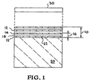
- Figure 1 shows a multilayer buffer layer on a reticle according to the present invention.
- Figure 2 graphically illustrates measurements of the surface of 30 nm diameter gold sphere before and after being coated at near-normal incidence with a Mo/Si multilayer coating.
- Figure 3 graphically illustrates measurements of the gold sphere of Figure 1 of the surface for Mo/Si deposited with the flux near-normal and off-normal.
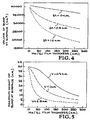
- Figure 4 graphically illustrates computer simulations of Mo/Si deposited on a 40 nm sphere showing the volumes of the bump at surface as a function of the film thickness.
- Figure 5 graphically illustrates computer simulations showing the maximum height of the bump at surface as a function of the film thickness.
- the present invention is directed to the mitigation of substrate defects in reticles or masks for extreme ultraviolet lithography (EUVL) using multilayer buffer layers.
- a multilayer film is deposited as a buffer layer 10 on a reticle substrate 20 to cover defects 22, such as small particle contaminants, pits, or scratches in the surface.
- the buffer layer 10 comprises a multilayer of at least a pair 16 (bilayer) of alternating layers 12,14 . Typically many pairs 16 , as shown, comprise the multilayer buffer layer 10 .
- the multilayer could comprise a plurality of trilayers or quadlayers, although bilayers are most typical.
- the buffer layer 10 is deposited on the reticle substrate 20 prior to deposition of a reflective coating 30 .
- the reflective coating may be a single layer, or a multilayer. Reflective coatings for EUV lithography are well known in the art.
- the multilayer buffer layer is atomically smooth and has good smoothing properties and low residual stress.
- the buffer layer 10 also exhibits volume contraction during growth due to intermixing at the interfaces of the layers 12,14. This intermixing creates an interlayer 18 between the layers 12,14 , formed of a mixture of the two materials.
- the layers 12,14 are comprised of two or more elements or alloys, such as Mo/Si or MoRu/Be.
- Multilayer films that should demonstrate the above-referenced characteristics include Me/Si, Me/Be, Me/B, Me/B 4 C, and Me/C, where Me is a metal or alloy such as Mo, W, Ni, Cr, Ru, Rh, MoRu, or MoRh.
- the multilayer buffer layer is deposited using an ultraclean ion beam sputtering process so that no defects are added in the fabrication operation.
- the multilayer buffer layer is deposited with minimal surface roughness (preferably ⁇ 3 ⁇ RMS) and low residual stress ( ⁇ 500MPa) so that it does not compromise the performance of the reflective coating deposited on top of the buffer layer.
- the reduction in defect height is controlled by surface relaxation during the film growth process, and the reduction in defect volume is controlled by the intermixing at the multilayer interfaces, when there is concomitant bilayer contraction, ⁇ .
- Figure 4 shows that with increasing Mo/Si film thickness, the defect volume (as measured by the volume of the bump at the surface) is reduced, and that this reduction is much greater with increased intermixing.
- Methods to increase the amount of intermixing and thereby decrease the defect volume include: (1) using a secondary ion source directed at the growing film, (2) changing the bilayer period thickness and/or the ratio of elements in the multilayers (e.g., Mo:Si in Mo/Si multilayers), (3) annealing during and/or after multilayer deposition, (4) changing the deposition system operating pressure, or (5) varying other conditions to alter the energetics of the deposition process.
- a large number of multilayer growth simulations were performed to study the structure of growth defects nucleated by spherical particles having diameters of 20, 40, and 60 nm.
- the relaxation parameter ⁇ and the bilayer contraction ⁇ were varied, since these should be adjustable in practice by changing the energetics of the deposition process.
- the variation in the maximum height and volume of the buffer layer was plotted for a 40 nm diameter particle.
- the relaxation parameter has opposite effects on the height and volume of the resulting perturbation. Increasing ⁇ reduces the maximum height of the surface, whereas decreasing ⁇ reduces the volume. This behavior is due to the effects of intermixing. When ⁇ is small, the perturbation remains localized and the surface slope is larger, thereby allowing the intermixing to be more effective in reducing the volume of the perturbation.
- the most important information is the structure of the growth defect at the top of the reflective coating.
- simulations were performed in which a reflective multilayer coating was grown on top of the buffer layer.
- the structure of the reflecting multilayer was [Mo(2.8 nm)/Si(4.2 nm)] x 40, corresponding to a standard high performance optical coating.
- the defect structure is defined by the maximum height and volume of the surface perturbation at the top surface of the reflective coating. The shape of the perturbation was always found to be a Guassian of revolution.
- the effect of buffer layers or growth defects nucleated by 20 and 60 nm diameter spherical particles were also determined.
- the relative decrease in the height and volume of the defects produced by the buffer layer are found to be independent of the particle size.
- the greatest challenge is to suppress the formation of defects from the largest particles, that is, in the 60 nm diameter range.
- the results indicate that the Mo/Si buffer layer will be able to reduce the maximum height of the defect to within the range of 3-6 nm and reduce the volume by as much as a factor of four. Larger reductions are possible with thicker buffer layers; however, the thickness is primarily limited by the residual stress of the film.
- the reticle substrate was assumed to be perfectly smooth.
- the rms roughness was found by integrating the power spectral density over the frequency range of 10 -6 - 1nm -1 .
- the amount of acceptable residual stress in the buffer layer is determined by how much stress the reticle substrate can tolerate and what amount of stress causes delamination of the buffer layer and overlying reflective layer. For example, it is well documented that the residual stress can be large in Mo/Si multilayer coatings; the typical stress for a magnetron sputtered Mo/Si reflective coating having 40 bilayers is ⁇ -400 MPa. The stress in the buffer layer and for the total thickness (buffer layer + reflective layer) must be below the threshold that causes the layers to flake off or delaminate.
- a simple implementation of a buffer layer is the use of a 40-bilayer Mo/Si multilayer coating.
- This buffer layer reduces the maximum height of the growth defect by over a factor of two for all particle sizes and also yields a ⁇ 25% reduction in the volume.
- a significant decrease in the defect size can be obtained by adjusting the growth parameters of the buffer layer.
- it is important to be able to independently control the bilayer contraction ⁇ and the relaxation parameter v. Then the contraction can be set to the optimum value of ⁇ 1.5 nm, and ⁇ can be adjusted to minimize either the height or the volume of the defect.
- the structure of the buffer layer is not optimized for high EUV reflectance; the reflective coating is so optimized.
- the power deposited at the film growth surface must be precisely controlled. Specifically, it is necessary to decouple the transport of the effluent (e.g., Mo and Si atoms) and the transport of energy to the growth surface. This can be achieved by using two ion beam sources: one to sputter the target material (e.g., Mo and Si atoms) onto the substrate, and a second ion source (e.g., argon) directly incident on the substrate to heat the growth surface.
- the film deposition should be performed at relatively high pressure ( ⁇ 1 mT) in order to minimize the energy of the incoming atoms and Ar neutrals reflected from the target. Then the energy flux at the growth surface will be determined primarily by the direct ion bombardment.
- the growth behavior of multilayer films can be significantly modified by ion bombardment, or ion-assisted deposition.
- a current density of 75 ⁇ A/cm 2 at 300 V is sufficient to produce complete intermixing of Mo and Si layers.
- Lower voltages ( ⁇ 100 V) increase the surface relaxation (larger v) with much less intermixing.
- direct ion bombardment of the growth surface can be used to control both the bilayer contraction ⁇ and the relaxation parameter v.
- a specific amount of intermixing can be obtained by applying a large energy flux for a short period during the transition between layers, that is, at the multilayer interfaces.
- the relaxation parameter v can be adjusted by applying a lower energy ion flux to the growth surface thoughout the deposition of the multilayer.
- a second ion source must be compatible with the defect-free deposition technology required for reticle production.
- the current technology is based on ion beam sputtering, so the use of a second ion source should not be problematic.
- direct ion bombardment of the substrate is a fundamentally different process from the perspective of particle management. Particles generated within the plasma of the ion gun or knocked off grids could be directly deposited onto the substrate, and management of such particle generation would be required.
- MoRu/Be is a smoothing buffer layer. Although these layers do not intermix as much as the interfaces of Mo/Si, there are other potential advantages. MoRu/Be has a very low residual stress, which permits much thicker films to be deposited without reticle bending or film delamination. Also, this buffer layer can be grown very thick while retaining its surface smoothness. The net smoothing effect is generally expected to increase with increasing buffer layer thickness, and therefore a thick MoRu/Be multilayer film is a viable buffer layer candidate. MoRu/Be multilayer films up to 1500 nm thick have been deposited with stress values of approximately 13MPa and surface roughness values of approximately 0.15 nm rms. The relaxation parameter for MoRu/Be multilayer film growth can be adjusted in a similar manner as mentioned above for Mo/Si multilayer film growth to provide more beneficial smoothing effects.
- the present invention mitigates the problem associated with defects on the surface of a reflective reticle, and effectively reduces the perturbation resulting from defects having a height of up to at least about 60 nm.
- the multilayer buffer layer intermediate the reticle substrate and the reflective coating, and by controlling the deposition of the buffer layer, localized structural imperfections on the reticle substrate do not produce imperfections in a reflective multilayer coating that perturb the reflected radiation field sufficiently to print at the wafer.
- This invention is particularly applicable for producing near-defect free reticles required for EUVL systems, thereby enabling the EUVL technology to be commercially viable.
Landscapes
- Physics & Mathematics (AREA)
- Engineering & Computer Science (AREA)
- General Physics & Mathematics (AREA)
- Chemical & Material Sciences (AREA)
- Nanotechnology (AREA)
- Crystallography & Structural Chemistry (AREA)
- Manufacturing & Machinery (AREA)
- Condensed Matter Physics & Semiconductors (AREA)
- Mathematical Physics (AREA)
- Theoretical Computer Science (AREA)
- Exposure Of Semiconductors, Excluding Electron Or Ion Beam Exposure (AREA)
- Preparing Plates And Mask In Photomechanical Process (AREA)
- Recrystallisation Techniques (AREA)
- Electron Beam Exposure (AREA)
- Semiconductor Integrated Circuits (AREA)
Applications Claiming Priority (3)
| Application Number | Priority Date | Filing Date | Title |
|---|---|---|---|
| US09/454,715 US6319635B1 (en) | 1999-12-06 | 1999-12-06 | Mitigation of substrate defects in reticles using multilayer buffer layers |
| US454715 | 1999-12-06 | ||
| PCT/US2000/031584 WO2001040871A1 (en) | 1999-12-06 | 2000-11-16 | Mitigation of substrate defects in reticles using multilayer buffer layers |
Publications (2)
| Publication Number | Publication Date |
|---|---|
| EP1248963A1 EP1248963A1 (en) | 2002-10-16 |
| EP1248963B1 true EP1248963B1 (en) | 2006-03-22 |
Family
ID=23805774
Family Applications (1)
| Application Number | Title | Priority Date | Filing Date |
|---|---|---|---|
| EP00980464A Expired - Lifetime EP1248963B1 (en) | 1999-12-06 | 2000-11-16 | Mitigation of substrate defects in reticles using multilayer buffer layers |
Country Status (8)
| Country | Link |
|---|---|
| US (2) | US6319635B1 (https=) |
| EP (1) | EP1248963B1 (https=) |
| JP (1) | JP4629943B2 (https=) |
| KR (1) | KR100704429B1 (https=) |
| AT (1) | ATE321294T1 (https=) |
| AU (1) | AU1772001A (https=) |
| DE (1) | DE60026876T2 (https=) |
| WO (1) | WO2001040871A1 (https=) |
Families Citing this family (74)
| Publication number | Priority date | Publication date | Assignee | Title |
|---|---|---|---|---|
| US6410193B1 (en) * | 1999-12-30 | 2002-06-25 | Intel Corporation | Method and apparatus for a reflective mask that is inspected at a first wavelength and exposed during semiconductor manufacturing at a second wavelength |
| US6821682B1 (en) * | 2000-09-26 | 2004-11-23 | The Euv Llc | Repair of localized defects in multilayer-coated reticle blanks for extreme ultraviolet lithography |
| JP5371162B2 (ja) * | 2000-10-13 | 2013-12-18 | 三星電子株式会社 | 反射型フォトマスク |
| US6635391B2 (en) * | 2000-12-28 | 2003-10-21 | The Regents Of The University Of California | Method for fabricating reticles for EUV lithography without the use of a patterned absorber |
| JP4320970B2 (ja) * | 2001-04-11 | 2009-08-26 | 株式会社ニコン | 多層膜反射鏡の製造方法 |
| US7843632B2 (en) * | 2006-08-16 | 2010-11-30 | Cymer, Inc. | EUV optics |
| US20030164998A1 (en) * | 2002-03-01 | 2003-09-04 | The Regents Of The University Of California | Ion-assisted deposition techniques for the planarization of topological defects |
| US7314688B2 (en) * | 2002-09-11 | 2008-01-01 | Hoya Corporation | Method of producing a reflection mask blank, method of producing a reflection mask, and method of producing a semiconductor device |
| US6834549B2 (en) * | 2003-04-03 | 2004-12-28 | Intel Corporation | Characterizing in-situ deformation of hard pellicle during fabrication and mounting with a sensor array |
| US7326502B2 (en) * | 2003-09-18 | 2008-02-05 | Intel Corporation | Multilayer coatings for EUV mask substrates |
| JP2005123292A (ja) * | 2003-10-15 | 2005-05-12 | Canon Inc | 収納装置、当該収納装置を用いた露光方法 |
| JP4538254B2 (ja) * | 2004-03-25 | 2010-09-08 | ルネサスエレクトロニクス株式会社 | Euvリソグラフィー用マスク基板及びその製造方法 |
| FR2884965B1 (fr) * | 2005-04-26 | 2007-06-08 | Commissariat Energie Atomique | Structure de blanc de masque ajustable pour masque euv a decalage de phase |
| JP4677857B2 (ja) | 2005-08-23 | 2011-04-27 | ヤマハ株式会社 | 楽器用部材または楽器とその製造方法 |
| US7504185B2 (en) * | 2005-10-03 | 2009-03-17 | Asahi Glass Company, Limited | Method for depositing multi-layer film of mask blank for EUV lithography and method for producing mask blank for EUV lithography |
| JP2007108194A (ja) * | 2005-10-11 | 2007-04-26 | Canon Inc | 多層膜ミラーの製造方法、光学系の製造方法、露光装置、及びデバイス製造方法 |
| JP4703354B2 (ja) * | 2005-10-14 | 2011-06-15 | Hoya株式会社 | 多層反射膜付き基板、その製造方法、反射型マスクブランクおよび反射型マスク |
| JP4905914B2 (ja) * | 2005-10-14 | 2012-03-28 | Hoya株式会社 | 多層反射膜付き基板、その製造方法、反射型マスクブランクおよび反射型マスク |
| JP4666365B2 (ja) | 2005-10-14 | 2011-04-06 | Hoya株式会社 | 多層反射膜付き基板、その製造方法、反射型マスクブランクおよび反射型マスク |
| JP4703353B2 (ja) * | 2005-10-14 | 2011-06-15 | Hoya株式会社 | 多層反射膜付き基板、その製造方法、反射型マスクブランクおよび反射型マスク |
| US20080261121A1 (en) * | 2007-04-20 | 2008-10-23 | Jeffrey Peter Gambino | Photolithography mask with protective silicide capping layer |
| US8194322B2 (en) * | 2007-04-23 | 2012-06-05 | Nikon Corporation | Multilayer-film reflective mirror, exposure apparatus, device manufacturing method, and manufacturing method of multilayer-film reflective mirror |
| DE102008042212A1 (de) | 2008-09-19 | 2010-04-01 | Carl Zeiss Smt Ag | Reflektives optisches Element und Verfahren zu seiner Herstellung |
| DE102009029471A1 (de) | 2009-09-15 | 2011-03-31 | Carl Zeiss Smt Gmbh | Spiegel zur Verwendung in einer Mikrolithographie-Projektionsbelichtungsanlage |
| JP5133967B2 (ja) * | 2009-11-16 | 2013-01-30 | ルネサスエレクトロニクス株式会社 | Euv露光方法 |
| EP2513686B1 (en) * | 2009-12-15 | 2019-04-10 | Carl Zeiss SMT GmbH | Reflective optical element for euv lithography |
| TWI509695B (zh) | 2010-06-10 | 2015-11-21 | Asm國際股份有限公司 | 使膜選擇性沈積於基板上的方法 |
| DE102010025033B4 (de) * | 2010-06-23 | 2021-02-11 | Carl Zeiss Smt Gmbh | Verfahren zur Defekterkennung und Reparatur von EUV-Masken |
| JP5340321B2 (ja) * | 2011-01-01 | 2013-11-13 | キヤノン株式会社 | ミラーおよびその製造方法、露光装置、ならびに、デバイス製造方法 |
| JP5816499B2 (ja) * | 2011-09-12 | 2015-11-18 | ルネサスエレクトロニクス株式会社 | Euvマスクの製造方法 |
| US9112003B2 (en) | 2011-12-09 | 2015-08-18 | Asm International N.V. | Selective formation of metallic films on metallic surfaces |
| CN103378246A (zh) * | 2012-04-18 | 2013-10-30 | 联胜光电股份有限公司 | 发光二极管的缓冲层结构 |
| US8828625B2 (en) | 2012-08-06 | 2014-09-09 | Taiwan Semiconductor Manufacturing Company, Ltd. | Extreme ultraviolet lithography mask and multilayer deposition method for fabricating same |
| US9354508B2 (en) | 2013-03-12 | 2016-05-31 | Applied Materials, Inc. | Planarized extreme ultraviolet lithography blank, and manufacturing and lithography systems therefor |
| US20140272684A1 (en) | 2013-03-12 | 2014-09-18 | Applied Materials, Inc. | Extreme ultraviolet lithography mask blank manufacturing system and method of operation therefor |
| US9612521B2 (en) * | 2013-03-12 | 2017-04-04 | Applied Materials, Inc. | Amorphous layer extreme ultraviolet lithography blank, and manufacturing and lithography systems therefor |
| US9632411B2 (en) | 2013-03-14 | 2017-04-25 | Applied Materials, Inc. | Vapor deposition deposited photoresist, and manufacturing and lithography systems therefor |
| TWI522729B (zh) * | 2013-08-30 | 2016-02-21 | Hoya股份有限公司 | Method for manufacturing a reflective mask substrate, a reflective mask substrate, a reflection type mask, and a semiconductor device |
| US9895715B2 (en) | 2014-02-04 | 2018-02-20 | Asm Ip Holding B.V. | Selective deposition of metals, metal oxides, and dielectrics |
| US10047435B2 (en) | 2014-04-16 | 2018-08-14 | Asm Ip Holding B.V. | Dual selective deposition |
| US9837271B2 (en) | 2014-07-18 | 2017-12-05 | Asm Ip Holding B.V. | Process for forming silicon-filled openings with a reduced occurrence of voids |
| US9443730B2 (en) * | 2014-07-18 | 2016-09-13 | Asm Ip Holding B.V. | Process for forming silicon-filled openings with a reduced occurrence of voids |
| US9490145B2 (en) | 2015-02-23 | 2016-11-08 | Asm Ip Holding B.V. | Removal of surface passivation |
| US10428421B2 (en) | 2015-08-03 | 2019-10-01 | Asm Ip Holding B.V. | Selective deposition on metal or metallic surfaces relative to dielectric surfaces |
| US10566185B2 (en) | 2015-08-05 | 2020-02-18 | Asm Ip Holding B.V. | Selective deposition of aluminum and nitrogen containing material |
| US10121699B2 (en) | 2015-08-05 | 2018-11-06 | Asm Ip Holding B.V. | Selective deposition of aluminum and nitrogen containing material |
| US10343186B2 (en) | 2015-10-09 | 2019-07-09 | Asm Ip Holding B.V. | Vapor phase deposition of organic films |
| US10695794B2 (en) | 2015-10-09 | 2020-06-30 | Asm Ip Holding B.V. | Vapor phase deposition of organic films |
| US10814349B2 (en) | 2015-10-09 | 2020-10-27 | Asm Ip Holding B.V. | Vapor phase deposition of organic films |
| US9981286B2 (en) | 2016-03-08 | 2018-05-29 | Asm Ip Holding B.V. | Selective formation of metal silicides |
| US10204782B2 (en) * | 2016-04-18 | 2019-02-12 | Imec Vzw | Combined anneal and selective deposition process |
| WO2017184357A1 (en) | 2016-04-18 | 2017-10-26 | Asm Ip Holding B.V. | Method of forming a directed self-assembled layer on a substrate |
| US11081342B2 (en) | 2016-05-05 | 2021-08-03 | Asm Ip Holding B.V. | Selective deposition using hydrophobic precursors |
| US10453701B2 (en) | 2016-06-01 | 2019-10-22 | Asm Ip Holding B.V. | Deposition of organic films |
| US10373820B2 (en) | 2016-06-01 | 2019-08-06 | Asm Ip Holding B.V. | Deposition of organic films |
| US9803277B1 (en) | 2016-06-08 | 2017-10-31 | Asm Ip Holding B.V. | Reaction chamber passivation and selective deposition of metallic films |
| US10014212B2 (en) | 2016-06-08 | 2018-07-03 | Asm Ip Holding B.V. | Selective deposition of metallic films |
| US11430656B2 (en) | 2016-11-29 | 2022-08-30 | Asm Ip Holding B.V. | Deposition of oxide thin films |
| US11094535B2 (en) | 2017-02-14 | 2021-08-17 | Asm Ip Holding B.V. | Selective passivation and selective deposition |
| US10460932B2 (en) | 2017-03-31 | 2019-10-29 | Asm Ip Holding B.V. | Semiconductor device with amorphous silicon filled gaps and methods for forming |
| US11501965B2 (en) | 2017-05-05 | 2022-11-15 | Asm Ip Holding B.V. | Plasma enhanced deposition processes for controlled formation of metal oxide thin films |
| JP7183187B2 (ja) | 2017-05-16 | 2022-12-05 | エーエスエム アイピー ホールディング ビー.ブイ. | 誘電体上の酸化物の選択的peald |
| US10900120B2 (en) | 2017-07-14 | 2021-01-26 | Asm Ip Holding B.V. | Passivation against vapor deposition |
| JP7146690B2 (ja) | 2018-05-02 | 2022-10-04 | エーエスエム アイピー ホールディング ビー.ブイ. | 堆積および除去を使用した選択的層形成 |
| JP2020056104A (ja) | 2018-10-02 | 2020-04-09 | エーエスエム アイピー ホールディング ビー.ブイ. | 選択的パッシベーションおよび選択的堆積 |
| US12482648B2 (en) | 2018-10-02 | 2025-11-25 | Asm Ip Holding B.V. | Selective passivation and selective deposition |
| US11965238B2 (en) | 2019-04-12 | 2024-04-23 | Asm Ip Holding B.V. | Selective deposition of metal oxides on metal surfaces |
| US11139163B2 (en) | 2019-10-31 | 2021-10-05 | Asm Ip Holding B.V. | Selective deposition of SiOC thin films |
| TWI862807B (zh) | 2020-03-30 | 2024-11-21 | 荷蘭商Asm Ip私人控股有限公司 | 相對於金屬表面在介電表面上之氧化矽的選擇性沉積 |
| TWI865747B (zh) | 2020-03-30 | 2024-12-11 | 荷蘭商Asm Ip私人控股有限公司 | 在兩不同表面上同時選擇性沉積兩不同材料 |
| TW202140832A (zh) | 2020-03-30 | 2021-11-01 | 荷蘭商Asm Ip私人控股有限公司 | 氧化矽在金屬表面上之選擇性沉積 |
| DE102020205788A1 (de) * | 2020-05-07 | 2021-11-11 | Carl Zeiss Smt Gmbh | Verfahren zum Herstellen von reflektiven optischen Elementen für den EUV-Wellenlängenbereich sowie reflektive optische Elemente für den EUV-Wellenlängenbereich |
| KR102246874B1 (ko) * | 2020-07-13 | 2021-04-30 | 삼성전자 주식회사 | 포토마스크, 포토마스크의 에러 보정 방법, 포토마스크를 이용하여 제조된 집적회로 소자 및 그 제조 방법 |
| CN121007748A (zh) * | 2025-08-19 | 2025-11-25 | 上海交通大学 | 一种减轻多孔透射样品窗帘效应的聚焦离子束制样方法 |
Citations (5)
| Publication number | Priority date | Publication date | Assignee | Title |
|---|---|---|---|---|
| JPH10177943A (ja) * | 1996-12-18 | 1998-06-30 | Hitachi Ltd | 投影露光方法 |
| US5928817A (en) * | 1997-12-22 | 1999-07-27 | Intel Corporation | Method of protecting an EUV mask from damage and contamination |
| US5935737A (en) * | 1997-12-22 | 1999-08-10 | Intel Corporation | Method for eliminating final euv mask repairs in the reflector region |
| WO2000075727A2 (en) * | 1999-06-07 | 2000-12-14 | The Regents Of The University Of California | Coatings on reflective mask substrates |
| WO2001009680A1 (fr) * | 1999-07-29 | 2001-02-08 | Commissariat A L'energie Atomique | Structure pour masque de lithographie en reflexion et procede pour sa realisation |
Family Cites Families (9)
| Publication number | Priority date | Publication date | Assignee | Title |
|---|---|---|---|---|
| JPS6197924A (ja) * | 1984-10-19 | 1986-05-16 | Nippon Sheet Glass Co Ltd | 保護カバ− |
| US5008156A (en) | 1986-11-07 | 1991-04-16 | Exion Technology, Inc. | Photochemically stable mid and deep ultraviolet pellicles |
| EP0416517B1 (en) | 1989-09-06 | 1995-05-10 | E.I. Du Pont De Nemours And Company | Non-glare pellicle |
| US5460908A (en) | 1991-08-02 | 1995-10-24 | Micron Technology, Inc. | Phase shifting retical fabrication method |
| JP3094648B2 (ja) * | 1992-05-06 | 2000-10-03 | 三菱電機株式会社 | X線マスク |
| JP3412898B2 (ja) * | 1994-03-02 | 2003-06-03 | キヤノン株式会社 | 反射型マスクの作製方法と作製装置、これによる反射型マスクを用いた露光装置とデバイス製造方法 |
| JP3578872B2 (ja) * | 1995-10-26 | 2004-10-20 | 三菱電機株式会社 | X線マスクの製造方法および加熱装置 |
| US5780161A (en) | 1996-11-06 | 1998-07-14 | Taiwan Semiconductor Manufacturing Company Ltd. | Non-absorbing anti-reflective coated (ARC) reticle using thin dielectric films and method of forming the reticle |
| US5922497A (en) | 1998-01-13 | 1999-07-13 | Micron Technology, Inc. | Lithographic imaging system |
-
1999
- 1999-12-06 US US09/454,715 patent/US6319635B1/en not_active Expired - Lifetime
-
2000
- 2000-11-16 KR KR1020027005534A patent/KR100704429B1/ko not_active Expired - Lifetime
- 2000-11-16 JP JP2001542276A patent/JP4629943B2/ja not_active Expired - Lifetime
- 2000-11-16 AT AT00980464T patent/ATE321294T1/de not_active IP Right Cessation
- 2000-11-16 WO PCT/US2000/031584 patent/WO2001040871A1/en not_active Ceased
- 2000-11-16 EP EP00980464A patent/EP1248963B1/en not_active Expired - Lifetime
- 2000-11-16 DE DE60026876T patent/DE60026876T2/de not_active Expired - Lifetime
- 2000-11-16 AU AU17720/01A patent/AU1772001A/en not_active Abandoned
-
2001
- 2001-03-27 US US09/819,156 patent/US6489066B2/en not_active Expired - Lifetime
Patent Citations (5)
| Publication number | Priority date | Publication date | Assignee | Title |
|---|---|---|---|---|
| JPH10177943A (ja) * | 1996-12-18 | 1998-06-30 | Hitachi Ltd | 投影露光方法 |
| US5928817A (en) * | 1997-12-22 | 1999-07-27 | Intel Corporation | Method of protecting an EUV mask from damage and contamination |
| US5935737A (en) * | 1997-12-22 | 1999-08-10 | Intel Corporation | Method for eliminating final euv mask repairs in the reflector region |
| WO2000075727A2 (en) * | 1999-06-07 | 2000-12-14 | The Regents Of The University Of California | Coatings on reflective mask substrates |
| WO2001009680A1 (fr) * | 1999-07-29 | 2001-02-08 | Commissariat A L'energie Atomique | Structure pour masque de lithographie en reflexion et procede pour sa realisation |
Non-Patent Citations (1)
| Title |
|---|
| PATENT ABSTRACTS OF JAPAN vol. 1998, no. 11 30 November 1998 (1998-11-30) * |
Also Published As
| Publication number | Publication date |
|---|---|
| KR20020061611A (ko) | 2002-07-24 |
| KR100704429B1 (ko) | 2007-04-06 |
| DE60026876T2 (de) | 2006-10-26 |
| WO2001040871A1 (en) | 2001-06-07 |
| US6319635B1 (en) | 2001-11-20 |
| EP1248963A1 (en) | 2002-10-16 |
| ATE321294T1 (de) | 2006-04-15 |
| JP2003515794A (ja) | 2003-05-07 |
| DE60026876D1 (de) | 2006-05-11 |
| JP4629943B2 (ja) | 2011-02-09 |
| US20010019803A1 (en) | 2001-09-06 |
| US6489066B2 (en) | 2002-12-03 |
| AU1772001A (en) | 2001-06-12 |
Similar Documents
| Publication | Publication Date | Title |
|---|---|---|
| EP1248963B1 (en) | Mitigation of substrate defects in reticles using multilayer buffer layers | |
| US7504185B2 (en) | Method for depositing multi-layer film of mask blank for EUV lithography and method for producing mask blank for EUV lithography | |
| Montcalm et al. | Multilayer reflective coatings for extreme-ultraviolet lithography | |
| EP1399781B1 (en) | Repair of amplitude defects in a multilayer coating | |
| CN102985587B (zh) | Mo/Si多层的等离子体辅助沉积 | |
| US8081384B2 (en) | Multilayer reflective film coated substrate, manufacturing method thereof, reflective mask blank, and reflective mask | |
| US7804648B2 (en) | Multilayer reflective film coated substrate, manufacturing method thereof, reflective mask blank, and reflective mask | |
| Mirkarimi et al. | An ion-assisted Mo-Si deposition process for planarizing reticle substrates for extreme ultraviolet lithography | |
| US20030164998A1 (en) | Ion-assisted deposition techniques for the planarization of topological defects | |
| US20050118533A1 (en) | Planarization of substrate pits and scratches | |
| Chassé et al. | Mo/Si multilayers for EUV lithography by ion beam sputter deposition | |
| Kim et al. | Characterization of Ru layer for capping/buffer application in EUVL mask | |
| Mirkarimi et al. | A silicon-based, sequential coat-and-etch process to fabricate nearly perfect substrate surfaces | |
| Mirkarimi et al. | Advancing the ion beam thin film planarization process for the smoothing of substrate particles | |
| Hau-Riege et al. | Defect repair for extreme-ultraviolet lithography (EUVL) mask blanks | |
| CN117026190B (zh) | 一种抑制极紫外钪基多层膜脆化的制备方法 | |
| Lee et al. | Combined absorber stack for optimization of the EUVL mask | |
| Fujiwara et al. | Ar+ ion beam machining of the carbon thin layer deposited on the Zerodur® substrate for EUVL projection optics | |
| Rastegar et al. | Nanopit smoothing by cleaning | |
| Hiruma et al. | Impact of interface treatment with assisted ion beam on Mo-Si multilayer formation for EUVL mask blanks | |
| Mirkarimi et al. | Advances in the Ion Beam Thin Film Planarization Process for Mitigating EUVL Mask Defects | |
| Spiller et al. | Multilayer reflective coatings for extreme-ultraviolet lithography |
Legal Events
| Date | Code | Title | Description |
|---|---|---|---|
| PUAI | Public reference made under article 153(3) epc to a published international application that has entered the european phase |
Free format text: ORIGINAL CODE: 0009012 |
|
| 17P | Request for examination filed |
Effective date: 20020527 |
|
| AK | Designated contracting states |
Kind code of ref document: A1 Designated state(s): AT BE CH CY DE DK ES FI FR GB GR IE IT LI LU MC NL PT SE TR |
|
| AX | Request for extension of the european patent |
Free format text: AL;LT;LV;MK;RO;SI |
|
| 17Q | First examination report despatched |
Effective date: 20041025 |
|
| GRAP | Despatch of communication of intention to grant a patent |
Free format text: ORIGINAL CODE: EPIDOSNIGR1 |
|
| GRAS | Grant fee paid |
Free format text: ORIGINAL CODE: EPIDOSNIGR3 |
|
| GRAA | (expected) grant |
Free format text: ORIGINAL CODE: 0009210 |
|
| AK | Designated contracting states |
Kind code of ref document: B1 Designated state(s): AT BE CH CY DE DK ES FI FR GB GR IE IT LI LU MC NL PT SE TR |
|
| PG25 | Lapsed in a contracting state [announced via postgrant information from national office to epo] |
Ref country code: IT Free format text: LAPSE BECAUSE OF FAILURE TO SUBMIT A TRANSLATION OF THE DESCRIPTION OR TO PAY THE FEE WITHIN THE PRESCRIBED TIME-LIMIT;WARNING: LAPSES OF ITALIAN PATENTS WITH EFFECTIVE DATE BEFORE 2007 MAY HAVE OCCURRED AT ANY TIME BEFORE 2007. THE CORRECT EFFECTIVE DATE MAY BE DIFFERENT FROM THE ONE RECORDED. Effective date: 20060322 Ref country code: AT Free format text: LAPSE BECAUSE OF FAILURE TO SUBMIT A TRANSLATION OF THE DESCRIPTION OR TO PAY THE FEE WITHIN THE PRESCRIBED TIME-LIMIT Effective date: 20060322 Ref country code: BE Free format text: LAPSE BECAUSE OF FAILURE TO SUBMIT A TRANSLATION OF THE DESCRIPTION OR TO PAY THE FEE WITHIN THE PRESCRIBED TIME-LIMIT Effective date: 20060322 Ref country code: LI Free format text: LAPSE BECAUSE OF FAILURE TO SUBMIT A TRANSLATION OF THE DESCRIPTION OR TO PAY THE FEE WITHIN THE PRESCRIBED TIME-LIMIT Effective date: 20060322 Ref country code: CH Free format text: LAPSE BECAUSE OF FAILURE TO SUBMIT A TRANSLATION OF THE DESCRIPTION OR TO PAY THE FEE WITHIN THE PRESCRIBED TIME-LIMIT Effective date: 20060322 |
|
| REG | Reference to a national code |
Ref country code: GB Ref legal event code: FG4D |
|
| REG | Reference to a national code |
Ref country code: CH Ref legal event code: EP |
|
| REG | Reference to a national code |
Ref country code: IE Ref legal event code: FG4D |
|
| RAP2 | Party data changed (patent owner data changed or rights of a patent transferred) |
Owner name: EUV LIMITED LIABILITY CORPORATION |
|
| REF | Corresponds to: |
Ref document number: 60026876 Country of ref document: DE Date of ref document: 20060511 Kind code of ref document: P |
|
| PG25 | Lapsed in a contracting state [announced via postgrant information from national office to epo] |
Ref country code: DK Free format text: LAPSE BECAUSE OF FAILURE TO SUBMIT A TRANSLATION OF THE DESCRIPTION OR TO PAY THE FEE WITHIN THE PRESCRIBED TIME-LIMIT Effective date: 20060622 Ref country code: SE Free format text: LAPSE BECAUSE OF FAILURE TO SUBMIT A TRANSLATION OF THE DESCRIPTION OR TO PAY THE FEE WITHIN THE PRESCRIBED TIME-LIMIT Effective date: 20060622 |
|
| NLT2 | Nl: modifications (of names), taken from the european patent patent bulletin |
Owner name: EUV LIMITED LIABILITY CORPORATION Effective date: 20060426 |
|
| PG25 | Lapsed in a contracting state [announced via postgrant information from national office to epo] |
Ref country code: ES Free format text: LAPSE BECAUSE OF FAILURE TO SUBMIT A TRANSLATION OF THE DESCRIPTION OR TO PAY THE FEE WITHIN THE PRESCRIBED TIME-LIMIT Effective date: 20060703 |
|
| PG25 | Lapsed in a contracting state [announced via postgrant information from national office to epo] |
Ref country code: PT Free format text: LAPSE BECAUSE OF FAILURE TO SUBMIT A TRANSLATION OF THE DESCRIPTION OR TO PAY THE FEE WITHIN THE PRESCRIBED TIME-LIMIT Effective date: 20060822 |
|
| REG | Reference to a national code |
Ref country code: CH Ref legal event code: PL |
|
| ET | Fr: translation filed | ||
| PG25 | Lapsed in a contracting state [announced via postgrant information from national office to epo] |
Ref country code: MC Free format text: LAPSE BECAUSE OF NON-PAYMENT OF DUE FEES Effective date: 20061130 |
|
| PLBE | No opposition filed within time limit |
Free format text: ORIGINAL CODE: 0009261 |
|
| STAA | Information on the status of an ep patent application or granted ep patent |
Free format text: STATUS: NO OPPOSITION FILED WITHIN TIME LIMIT |
|
| 26N | No opposition filed |
Effective date: 20061227 |
|
| PG25 | Lapsed in a contracting state [announced via postgrant information from national office to epo] |
Ref country code: GR Free format text: LAPSE BECAUSE OF FAILURE TO SUBMIT A TRANSLATION OF THE DESCRIPTION OR TO PAY THE FEE WITHIN THE PRESCRIBED TIME-LIMIT Effective date: 20060623 |
|
| PG25 | Lapsed in a contracting state [announced via postgrant information from national office to epo] |
Ref country code: FI Free format text: LAPSE BECAUSE OF FAILURE TO SUBMIT A TRANSLATION OF THE DESCRIPTION OR TO PAY THE FEE WITHIN THE PRESCRIBED TIME-LIMIT Effective date: 20060322 |
|
| PG25 | Lapsed in a contracting state [announced via postgrant information from national office to epo] |
Ref country code: LU Free format text: LAPSE BECAUSE OF NON-PAYMENT OF DUE FEES Effective date: 20061116 Ref country code: TR Free format text: LAPSE BECAUSE OF FAILURE TO SUBMIT A TRANSLATION OF THE DESCRIPTION OR TO PAY THE FEE WITHIN THE PRESCRIBED TIME-LIMIT Effective date: 20060322 |
|
| PG25 | Lapsed in a contracting state [announced via postgrant information from national office to epo] |
Ref country code: CY Free format text: LAPSE BECAUSE OF FAILURE TO SUBMIT A TRANSLATION OF THE DESCRIPTION OR TO PAY THE FEE WITHIN THE PRESCRIBED TIME-LIMIT Effective date: 20060322 |
|
| REG | Reference to a national code |
Ref country code: FR Ref legal event code: PLFP Year of fee payment: 16 |
|
| REG | Reference to a national code |
Ref country code: FR Ref legal event code: PLFP Year of fee payment: 17 |
|
| REG | Reference to a national code |
Ref country code: FR Ref legal event code: PLFP Year of fee payment: 18 |
|
| REG | Reference to a national code |
Ref country code: FR Ref legal event code: PLFP Year of fee payment: 19 |
|
| PGFP | Annual fee paid to national office [announced via postgrant information from national office to epo] |
Ref country code: DE Payment date: 20191105 Year of fee payment: 20 Ref country code: IE Payment date: 20191111 Year of fee payment: 20 Ref country code: NL Payment date: 20191114 Year of fee payment: 20 |
|
| PGFP | Annual fee paid to national office [announced via postgrant information from national office to epo] |
Ref country code: IT Payment date: 20191108 Year of fee payment: 20 Ref country code: FR Payment date: 20191014 Year of fee payment: 20 |
|
| PGFP | Annual fee paid to national office [announced via postgrant information from national office to epo] |
Ref country code: GB Payment date: 20191115 Year of fee payment: 20 |
|
| REG | Reference to a national code |
Ref country code: DE Ref legal event code: R071 Ref document number: 60026876 Country of ref document: DE |
|
| REG | Reference to a national code |
Ref country code: NL Ref legal event code: MK Effective date: 20201115 |
|
| REG | Reference to a national code |
Ref country code: GB Ref legal event code: PE20 Expiry date: 20201115 |
|
| REG | Reference to a national code |
Ref country code: IE Ref legal event code: MK9A |
|
| PG25 | Lapsed in a contracting state [announced via postgrant information from national office to epo] |
Ref country code: GB Free format text: LAPSE BECAUSE OF EXPIRATION OF PROTECTION Effective date: 20201115 Ref country code: IE Free format text: LAPSE BECAUSE OF EXPIRATION OF PROTECTION Effective date: 20201116 |