EP1248274B1 - Schaltanordnung für ein Kraftfahrzeug mit stossabsorbierende Vorrichtung - Google Patents
Schaltanordnung für ein Kraftfahrzeug mit stossabsorbierende Vorrichtung Download PDFInfo
- Publication number
- EP1248274B1 EP1248274B1 EP02252444A EP02252444A EP1248274B1 EP 1248274 B1 EP1248274 B1 EP 1248274B1 EP 02252444 A EP02252444 A EP 02252444A EP 02252444 A EP02252444 A EP 02252444A EP 1248274 B1 EP1248274 B1 EP 1248274B1
- Authority
- EP
- European Patent Office
- Prior art keywords
- housing
- knob
- circuit board
- shaft
- switch assembly
- Prior art date
- Legal status (The legal status is an assumption and is not a legal conclusion. Google has not performed a legal analysis and makes no representation as to the accuracy of the status listed.)
- Expired - Lifetime
Links
Images








Classifications
-
- B—PERFORMING OPERATIONS; TRANSPORTING
- B60—VEHICLES IN GENERAL
- B60R—VEHICLES, VEHICLE FITTINGS, OR VEHICLE PARTS, NOT OTHERWISE PROVIDED FOR
- B60R21/00—Arrangements or fittings on vehicles for protecting or preventing injuries to occupants or pedestrians in case of accidents or other traffic risks
- B60R21/02—Occupant safety arrangements or fittings, e.g. crash pads
- B60R21/055—Padded or energy-absorbing fittings, e.g. seat belt anchors
-
- H—ELECTRICITY
- H01—ELECTRIC ELEMENTS
- H01H—ELECTRIC SWITCHES; RELAYS; SELECTORS; EMERGENCY PROTECTIVE DEVICES
- H01H3/00—Mechanisms for operating contacts
- H01H3/02—Operating parts, i.e. for operating driving mechanism by a mechanical force external to the switch
- H01H3/08—Turn knobs
-
- H—ELECTRICITY
- H01—ELECTRIC ELEMENTS
- H01H—ELECTRIC SWITCHES; RELAYS; SELECTORS; EMERGENCY PROTECTIVE DEVICES
- H01H3/00—Mechanisms for operating contacts
- H01H3/02—Operating parts, i.e. for operating driving mechanism by a mechanical force external to the switch
- H01H2003/026—Operating parts, i.e. for operating driving mechanism by a mechanical force external to the switch specially adapted to avoid injury to occupants of a car during an accident
-
- H—ELECTRICITY
- H01—ELECTRIC ELEMENTS
- H01H—ELECTRIC SWITCHES; RELAYS; SELECTORS; EMERGENCY PROTECTIVE DEVICES
- H01H3/00—Mechanisms for operating contacts
- H01H3/02—Operating parts, i.e. for operating driving mechanism by a mechanical force external to the switch
- H01H2003/0286—Operating parts, i.e. for operating driving mechanism by a mechanical force external to the switch having a weak point breaking or uncoupling on abnormal external force
-
- H—ELECTRICITY
- H01—ELECTRIC ELEMENTS
- H01H—ELECTRIC SWITCHES; RELAYS; SELECTORS; EMERGENCY PROTECTIVE DEVICES
- H01H9/00—Details of switching devices, not covered by groups H01H1/00 - H01H7/00
- H01H9/02—Bases, casings, or covers
-
- H—ELECTRICITY
- H05—ELECTRIC TECHNIQUES NOT OTHERWISE PROVIDED FOR
- H05K—PRINTED CIRCUITS; CASINGS OR CONSTRUCTIONAL DETAILS OF ELECTRIC APPARATUS; MANUFACTURE OF ASSEMBLAGES OF ELECTRICAL COMPONENTS
- H05K1/00—Printed circuits
- H05K1/02—Details
Definitions
- the present invention relates to a switch assembly of an automobile, and more particularly to a switch assembly having a load absorbing apparatus for absorbing a load applied to a knob of a switch assembly.
- an internal controlling apparatus having air vent nozzles and a plurality of mode switches for operating a radio and an air conditioning apparatus is installed at a center facia panel installed at the central portion of a dashboard of an automobile.
- a variety of knobs for manipulating the internal controlling apparatus are installed at the mode switches.
- the knobs protrude from the surface of the center facia panel and the heights of the knobs protruding from the surface of the center facia panel are regulated by laws for the safety of a passenger in automobile accidents.
- knobs of most mode switches installed at the internal controlling apparatus are designed not to protrude above a regulated height.
- the knobs or protrusions protruding over a predetermined height for the convenience of manipulation for a passenger, when an impact/load of a predetermined amount (38.5 kgf) is applied by a passenger in an automobile accident, the knobs or protrusions are designed to absorb the impact/load by being pushed into the center facia panel to protect the passenger.
- FIG. 1 is a view showing the arrangement of the mode switches installed at the center facia panel.
- FIG. 2 is a sectional view showing a conventional impact/load absorbing apparatus of a knob protruding over a predetermined height from the surface of the center facia panel.
- a knob impact/load absorbing apparatus for a mode switch of an automobile includes a housing 1 inserted into a center facia panel 100 of an automobile and fixed to the center facia panel 100, and a shaft 2 installed at the housing 1 to be capable of rotating and sliding in the lengthwise direction.
- a knob 3 protruding from the center facia panel 100 is installed at one end portion of the shaft 2.
- the shaft 2 is elastically biased toward the knob 3 by a buffer spring 4 installed in the housing 1.
- the impact/load absorbing apparatus of a mode switch having the above structure protects a passenger from injury by absorbing the impact/load as the buffer spring 4 is compressed.
- the impact/load absorbing apparatus for a mode switch of an automobile generates noise during rotation of the shaft 2 since the shaft 2 is elastically supported by the buffer spring 4. Also, there is lots of restrictions in designing the mode switch.
- Japanese Patent Publication No. Hei 7-201250 discloses a switch having an impact/load absorbing mechanism attached thereto.
- the switch with an impact/load absorbing mechanism includes a printed board to which a push button switch is attached. Since the printed board is elastically supported at a base by springs, an impact/load applied during manipulation of the push button switch is absorbed by retracting the printed board.
- Japanese Patent Publication Nos. 2000-222974 and Hei 8-138480 disclose switches for impact/load absorption.
- Japanese Patent Publication No. 8-138480 the structure of a switch in which elastic elements are installed in the lengthwise direction of a shaft for absorbing an impact/load is disclosed.
- US-A-5 235 648 discloses another example of load absorbing means for a switch.
- the present invention provides a load absorbing switch assembly of an automobile, comprising:
- the breaking portion has at least one notch so that the circuit board between the main body area and the fixing area is broken by an impact/load applied from the knob and the shaft.
- the support portion comprises a plurality of bosses protruding from the housing and a plurality of coupling members fixing the circuit board to the bosses.
- the breaking portion has at least one slot formed at the mounting portion and at least one connection portion to be broken by an impact/load is installed between slots.
- the invention provides a load absorbing switch assembly of an automobile comprising:
- the breaking portion has a plurality of slots for weakening the structure of the housing formed around each of the bosses so that the housing around each of the bosses is broken by an impact/load applied from the knob and the shaft.
- a load absorbing switch assembly of an automobile is provided to protect a passenger from a knob protruding from a center facia panel in an automobile accident when there is a need for the knob to protrude from the center facia panel by more than a predetermined restricted height. Since the installation of the mode switch assembly is not limited to a center facia panel, it can be installed at any place in the automobile for example ceiling or door of the automobile.
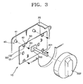
- FIG. 3 shows a mode switch assembly of an automobile according to a first embodiment of the present invention.
- a mode switch assembly 10 of an automobile includes a housing 20 disposed inside a center facia panel 100 inside the automobile, a circuit board 30 installed inside the housing 20 in which a switch 200 having a shaft 201, a support portion 40 for supporting the circuit board 30 to be separated a predetermined distance from the housing 20, and a knob 202 installed at the shaft 201 to protrude from the center facia panel 100.
- the mode switch assembly 10 includes a breaking portion 50 that allows the knob 202 and the shaft 201 to retreat with respect to the center facia panel 100 as part of the circuit board 30 is broken by an impact/load applied to the shaft 201 from the knob 202.
- the support portion 40 for supporting the circuit board 30 with respect to the housing 20 fixes the circuit board 30 to the housing 20.
- the support portion 40 includes a plurality of bosses 41 protruding from the inner side of the housing 20 to support the circuit board 30 and a plurality of coupling members 43 coupled to the bosses 41 through coupling holes 42 formed in the circuit board 30 to fix the circuit board 30 to the bosses 41.
- the coupling members 43 may be set screws screw-coupled to the bosses 41.
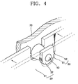
- the breaking portion 50 shown in FIG. 4 allows the knob 202 to be pushed into the center facia panel 100 as part of the circuit board 30 is broken by an impact/load applied in the lengthwise direction of the shaft 201 via the knob 202 and the shaft 201.
- a plurality of slots 51 are formed around each of the coupling holes 42 of the circuit board 30 at a predetermined interval to divide the circuit board 30 into a main body area 31 and a fixing area 32.
- At least one connection portion 52 connecting the main body area 31 and the fixing area 32 is formed between the slots 51.
- the size and number of the slots 51 and the connection portion 52 can be designed to satisfy the restriction regulation of an automobile so that the connection portion 52 can be broken by an impact/load applied through the knob 202 and the shaft 201.
- the breaking portion 50 can be a notch 53 formed between the main body area 31 and the fixing area 32 of the circuit board 30, as shown in FIG. 5.
- the notch 53 can be a groove(s) continuously or discontinuously formed in the circuit board 30.
- FIG. 6 shows another example of the breaking portion 50 in the mode switch assembly of an automobile.
- the breaking portion 50 is formed such that the knob 202 can retreat with respect to the center facia panel 100 by making a portion around the boss 41 of the housing 20 relatively weak so that the portion of the housing 20 can be broken by an impact/load transferred through the knob 202 and the shaft 201.
- at least one slot 56 is formed in the housing 20 around the boss 41 to thus form a housing main body area 21 and a housing boss area 22 . As the slot 56 is formed, the housing main body area 21 and the housing boss area 22 are connected by a connection portion 55.
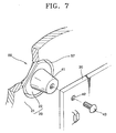
- the breaking portion 50 formed at the housing 20 may be a notch 57 formed around the boss 41, as shown in FIG. 7.
- the notch 57 can be formed by a groove(s) continuously or discontinuously formed in the housing 20 around the boss 41.
- at least one slot 58 is preferably formed at a portion of the housing 20 where the notch 57 is formed, as shown in FIG. 8, so that the housing 20 can be easily broken by an impact/load applied to the boss 41.
- the circuit board 30 is arranged in front of the boss 41 formed on the inner side surface of the housing 20 and fixed to the housing 20 by the coupling member 43. Then, the shaft 201 of the switch 200 installed at the circuit board 30 is arranged to protrude above the center facia panel 100. The knob 202 is coupled to the shaft 201.
- connection portion 52 is broken as the load concentrates on the connection portion 52 which is formed around each of the coupling holes 42 of the circuit board 30 and connects the main body area 31 of the circuit board 30 and the fixing area 32 supported by the bosses 41.
- the circuit board 30 thus retracts by being separated from the bosses 41.
- the knob 202 as well as the shaft 201 is moved together with the circuit board 30 toward the inner side surface of the housing 20.
- the knob 202 is pushed into the center facia panel 100, the impact/load received by a passenger is lowered.
- FIG. 9 shows another preferred embodiment of a mode switch assembly of an automobile of the present invention.
- a mode switch assembly includes a housing 20 disposed in the center facia panel 100 inside the automobile, a circuit board 30 installed in the housing 20 where the switch having the shaft 201 is installed, and a control cover 60 which the shaft 201 penetrates that is fixed to the housing 20, and which includes a front panel.
- the knob 202 is installed on the shaft 201 protruding from the front panel 61.
- a mounting portion 62 for mounting the housing, circuit board and control cover to the center facia panel is provided at either side of the control cover 60.
- a breaking portion 70 is formed on the mounting portion 62 on at least one side of the control cover 60, so that the knob 202 retreats with respect to the center facia panel 100 by an impact/load applied to the knob 202 and the shaft 201.
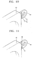
- a plurality of slots 71 are formed in the mounting portion 62 at a predetermined interval and a connection portion 72 to be broken by an impact/load is formed between the slots 71, as shown in FIGS. 9 and 10.
- a breaking portion 80 includes a structurally weak portion at one side of at least one of the main body of the control cover 60 and a mounting portion 62.
- the weak portion 73 may be a notch (not shown) formed continuously or discontinuously around a portion fixed to the housing 20 in the main body of the control cover 60.
- the weak portion 73 may be a notch (or groove) 73 formed continuously or discontinuously at a boundary portion between the mounting portion 62 and the main body of the control cover 60, as shown in FIG. 11.
- both the slot 71 and the notch 73 can be formed in the mounting portion 62.
- the mounting portion 62 of the control cover 60 is broken or the portion where the control cover 60 is coupled to the housing 20 is broken so that the impact/load is lowered. That is, when an impact/load over a predetermined amount is applied to the knob 202, the impact/load is transferred to the control cover 60 though the shaft 201, the circuit board 30, and the housing 20. Thus, the transferred impact/load concentrates on the connection portion 72 formed at the mounting portion 62 and the connection portion 72 is broken.
- the housing 20 and the control cover 60 are separated from the center facia panel 100 and retracted inside the center facia panel 100. Consequently, the knob 202 is pushed into the center facia panel 100 with the housing 20 and the control cover 60 so that the impact/load received by the passenger is lowered.
- a part of the structure is broken to alleviate an impact/load as described.
- electrical/electronic damage to other parts is prevented by the relative movement which lowers an impact/load applied by the knob 202 and damage to the related parts is minimized and durability is improved.
- the impact/load absorbing switch assembly eases the restriction on the impact/load to be taken into consideration at the early stage of design, not only the knob and control cover but also the center facia panel can be freely designed.
- FIGS. 12 and 13 show another embodiment of a mode switch assembly of an automobile not claimed in the present invention.
- a mode switch assembly includes the housing 20 disposed in the center facia panel 100 inside the automobile, a circuit board 30 installed in the housing 20 where the switch having the shaft 201 is installed, and a control cover 60 that the shaft 201 penetrates coupled to the center facia panel 100.
- the control cover 60 is coupled to the center facia panel by mounting portions 62 including slots 71 and connecting portions 72 as in the embodiment of Figures 9 and 10.
- One end portion of the shaft 201 is coupled to a hole 204 formed in a hub 203 of the knob 202 by a coupling unit to be capable of sliding.
- the coupling unit 80 may include a flat surface 81 formed on the outer circumference of the shaft 201 in the lengthwise direction and a rotation prevention portion 82 formed on the inner surface of the hole 204 of the hub 203 to contact the flat surface 81 of the shaft 201.
- a spline may be formed on the outer circumferential surface of the shaft 201 and the inner circumferential surface of the hole 204.
- the shaft 201 and the hub 203 are coupled such that they cannot be separated or slide without applying an external force.
- An impact/load absorbing portion 90 for absorbing an impact/load applied to the knob 202 is installed between the bottom surface of the hole 204 formed in the hub 203 and the end portion of the shaft 201.
- the impact/load absorbing portion 90 may be an elastic member 91 disposed between the bottom surface of the hole 204 and the end portion of the shaft 201.
- the elastic member 91 is a bar formed of a rubber member having a diameter less than that of the shaft 201.
- the elastic member 91 may be a coil spring.
- the elastic support portion 95 for elastically supporting the knob 202 and guiding reciprocation of the knob 202 is provided between the control cover 60 and the knob 202.
- the elastic support portion 95 includes a flange portion 95a circularly formed around the hub 203 on the inner circumferential surface of the knob 202, an inner flange portion 95b formed on the control cover 60 to extend toward the knob 202, and a guide portion 95c installed at the end portion of the inner flange portion 95b for guiding the end portion of the inner flange portion 95b.
- the elastic support portion 95 is not limited by the above-described preferred embodiment and any structure capable of elastically supporting the knob 202 can be adopted.
- the knob 202 In the mode switch assembly of an automobile having the impact/load absorbing apparatus having the above structure, when an impact/load over a predetermined amount is applied to the knob 202, the knob 202 is moved along the shaft 201 by the impact/load. Accordingly, as the knob 202 presses the elastic member 91 located in the hole 204 of the hub 203, the elastic member 91 is bent. As the elastic member 91 is bent, the knob 202 is compressed and moved within a range satisfying the restrictions on the amount of protrusion of the knob. When the external force is removed, the knob 202 is returned to the original position by the elastic support portion 95 and the elastic member 91.
- the guide portion 95c formed at the end portion of the inner flange portion 95b of the control cover 60 is inserted into the inner flange portion 95b of the knob 202 and guides the knob 202 to stably move forward and backward and simultaneously support the knob 202 not to be pushed into the housing 20.
- the knob 202 is moved into the control cover 60 so as to be pushed into the center facia panel 100.
- an impact/load received by a passenger can be lowered. Since the impact/load absorbing portion 90 reduces damage by the knob 202 to other parts as an impact/load is absorbed by the bending of the elastic member 91 and the knob 202 returns to its original state after the impact/load is removed, the damage to the parts can be minimized.
- the breaking portion formed at the circuit board, the housing, or the control cover is broken and the knob is moved.
- the impact/load is lowered and the damage to the passenger can be minimized.
- parts can be prevented from being damaged by the impact/load applied to the knob.
Landscapes
- Engineering & Computer Science (AREA)
- Mechanical Engineering (AREA)
- Switch Cases, Indication, And Locking (AREA)
- Push-Button Switches (AREA)
- Switches With Compound Operations (AREA)
- Instrument Panels (AREA)
- Rotary Switch, Piano Key Switch, And Lever Switch (AREA)
Claims (14)
- Lastabsorbierende Schalteranordnung (10) eines Automobilsmit einem Gehäuse (20), das in einer Mittelkonsole (100) eines Automobils angeordnet ist,mit einem Trägerabschnitt (40) zur Halterung einer Schaltungsplatine (30) in einem vorbestimmten Abstand von dem Gehäuse (20), wobei der Trägerabschnitt in einem Befestigungsbereich (32) an der Schaltungsplatine (30) befestigt ist,mit einem auf einem Schaft (201) angeordneten Knopf (202), der aus der Mittelkonsole (100) herausragt,dadurch gekennzeichnet,
dass die Schaltungsplatine (30) in dem Gehäuse (20) installiert ist und ein den Schaft (201) aufweisender Schalter (200) in einem Hauptkörperbereich (31) der Schaltungsplatine (30) installiert ist, und
dass um den Trägerabschnitt herum entweder in der Schaltungsplatine (30) oder in dem Gehäuse (20) eine Bruchstelle angeordnet ist, um den Knopf (202), den Schaft (201) und mindestens den Hauptkörperbereich (31) der Schaltungsplatine (30) gegenüber der Mittelkonsole (100) zurückweichen zu lassen, wenn die Bruchstelle durch eine über den Knopf (202) auf den Schaft (201) ausgeübte Last gebrochen wird. - Schalteranordnung nach Anspruch 1, dadurch gekennzeichnet, dass die Bruchstelle mindestens eine Kerbe (53) aufweist, die in der Schaltungsplatine zwischen dem Hauptkörperbereich (31) und dem Befestigungsbereich (32) gebildet ist, so dass die Schaltungsplatine (30) durch eine von dem Knopf (202) und dem Schaft (201) ausgeübte Last gebrochen wird.
- Schalteranordnung nach Anspruch 1, dadurch gekennzeichnet, dass die Bruchstelle mindestens einen Schlitz (51) aufweist, der in der Schaltungsplatine (30) zwischen dem Hauptkörperbereich (31) und dem Befestigungsbereich (32) gebildet ist, so dass die Schaltungsplatine durch eine von dem Knopf (202) und dem Schaft (201) ausgeübte Last gebrochen wird.
- Schalteranordnung nach Anspruch 1 oder 3, dadurch gekennzeichnet, dass die Bruchstelle mindestens eine Nut aufweist, die zwischen dem Hauptkörperbereich (31) und dem Befestigungsbereich (32) gebildet ist, so dass die Schaltungsplatine (30) durch eine von dem Knopf (202) und dem Schaft (201) ausgeübte Last gebrochen wird.
- Schalteranordnung nach Anspruch 1, dadurch gekennzeichnet, dass der Trägerabschnitt (40) eine Mehrzahl von Stutzen (41), die von dem Gehäuse (20) vorstehen, und eine Mehrzahl von Befestigungselementen (43) zum Befestigen der Schaltungsplatine (30) an den Stutzen aufweist.
- Schalteranordnung nach Anspruch 5, dadurch gekennzeichnet, dass die Bruchstelle mindestens eine Mehrzahl von Schlitzen (56) aufweist, die in dem Gehäuse (20) um jeden der Stutzen (41) herum zum Schwächen der Struktur des Gehäuses gebildet sind, so dass das Gehäuse um jeden der Stutzen herum gebrochen wird, wenn von dem Knopf (202) und dem Schaft (201) eine Last ausgeübt wird.
- Schalteranordnung nach Anspruch 5, dadurch gekennzeichnet, dass die Bruchstelle eine Mehrzahl von Schlitzen (51) aufweist, die in einem vorbestimmten Abstand durchgehend um einen Abschnitt der Schaltungsplatine (30) gebildet sind, in dem die Schaltungsplatine an den Stutzen (41) befestigt ist.
- Schalteranordnung nach Anspruch 1, dadurch gekennzeichnet, dass die Bruchstelle mindestens eine Kerbe (57) oder einen Schlitz (56) aufweist, die in dem Gehäuse (20) gebildet sind, so dass das Gehäuse gebrochen wird, wenn von dem Knopf (202) und dem Schaft (201) eine Last ausgeübt wird.
- Lastabsorbierende Schalteranordnung (10) eines Automobils
mit einem Gehäuse (20), das in einer Mittelkonsole (100) eines Automobils angeordnet ist,
mit einem Trägerabschnitt (40) zur Halterung einer Schaltungsplatine (30), die um einen vorbestimmten Abstand von dem Gehäuse (20) getrennt sein soll,
mit einer Steuerungsabdeckung (60), an der das Gehäuse (20) befestigt ist, durch die der Schaft (201) hindurchgeht und an der ein Befestigungsabschnitt (62) angeformt ist, der mit der Mittelkonsole (100) verbunden ist,
mit einem auf einem Endabschnitt des Schaftes (201) angeordneten Knopf (202), der aus der Mittelkonsole (100) herausragt,
dadurch gekennzeichnet,
dass die Schaltungsplatine (30) in dem Gehäuse (20) installiert ist und ein den Schaft (201) aufweisender Schalter (200) auf einem Hauptkörperbereich (31) der Schaltungsplatine (30) installiert ist, und
dass eine Bruchstelle an oder zwischen mindestens einer Seite der Steuerungsabdeckung (60) und dem Befestigungsabschnitt (62) gebildet ist, um den Knopf (202), den Schaft (201) und den Hauptkörperbereich (31) der Schaltungsplatine (30) gegenüber der Mittelkonsole (100) zurückweichen zu lassen, wenn die Bruchstelle durch eine auf den Knopf (202) und den Schaft (201) ausgeübte Last gebrochen wird. - Schalteranordnung nach Anspruch 9, dadurch gekennzeichnet, dass die Bruchstelle mindestens einen Schlitz (71) aufweist, der am Befestigungsabschnitt (62) gebildet ist, und dass mindestens ein Verbindungsabschnitt (72) neben dem Schlitz vorgesehen ist, der durch eine Last gebrochen wird.
- Schalteranordnung nach Anspruch 9, dadurch gekennzeichnet, dass die Bruchstelle mindestens eine Kerbe (73) aufweist, die im Grenzabschnitt zwischen dem Befestigungsabschnitt (62) und der Steuerungsabdeckung (60) gebildet ist.
- Schalteranordnung nach Anspruch 9, dadurch gekennzeichnet, dass die Bruchstelle mindestens eine Nut aufweist, die im Grenzabschnitt zwischen dem Befestigungsabschnitt (62) und der Steuerungsabdeckung (60) gebildet ist.
- Schalteranordnung nach Anspruch 9, dadurch gekennzeichnet, dass die Bruchstelle mindestens eine Kerbe aufweist, die in der Steuerungsabdeckung (60) im Grenzabschnitt zwischen dem Gehäuse (20) und der Steuerungsabdeckung (60) gebildet ist.
- Lastabsorbierende Schalteranordnung Anspruch 1, dadurch gekennzeichnet, dass die Anordnung darüber hinaus folgende Teile enthält:eine Steuerungsabdeckung (60), an der das Gehäuse befestigt ist, durch die der Schaft hindurchgeht und an der ein Befestigungsabschnitt (62) angeformt ist, der mit der Mittelkonsole verbunden ist, undeine Hilfsbruchstelle, die an mindestens einer Seite der Steuerungsabdeckung und dem Befestigungsabschnitt vorgesehen ist, um es dem Knopf zu ermöglichen, gegenüber der Mittelkonsole zurückzuweichen, wenn auf den Knopf und den Schaft eine Last ausgeübt wird.
Applications Claiming Priority (4)
| Application Number | Priority Date | Filing Date | Title |
|---|---|---|---|
| KR2001017914 | 2001-04-04 | ||
| KR20010017914 | 2001-04-04 | ||
| KR2001086737 | 2001-12-28 | ||
| KR10-2001-0086737A KR100461979B1 (ko) | 2001-04-04 | 2001-12-28 | 차량의 모드스위치용 노브 충격흡수구조 |
Publications (3)
| Publication Number | Publication Date |
|---|---|
| EP1248274A2 EP1248274A2 (de) | 2002-10-09 |
| EP1248274A3 EP1248274A3 (de) | 2004-09-08 |
| EP1248274B1 true EP1248274B1 (de) | 2007-06-13 |
Family
ID=26638951
Family Applications (1)
| Application Number | Title | Priority Date | Filing Date |
|---|---|---|---|
| EP02252444A Expired - Lifetime EP1248274B1 (de) | 2001-04-04 | 2002-04-04 | Schaltanordnung für ein Kraftfahrzeug mit stossabsorbierende Vorrichtung |
Country Status (4)
| Country | Link |
|---|---|
| US (1) | US6696769B2 (de) |
| EP (1) | EP1248274B1 (de) |
| JP (1) | JP3595858B2 (de) |
| DE (1) | DE60220574T2 (de) |
Families Citing this family (26)
| Publication number | Priority date | Publication date | Assignee | Title |
|---|---|---|---|---|
| KR100461979B1 (ko) * | 2001-04-04 | 2004-12-14 | 한라공조주식회사 | 차량의 모드스위치용 노브 충격흡수구조 |
| US6696769B2 (en) * | 2001-04-04 | 2004-02-24 | Halla Climate Control Corporation | Mode switch assembly of automobile having impact/load absorbing apparatus |
| FR2843270A1 (fr) * | 2002-08-02 | 2004-02-06 | Bruno Coissac | Moyen de fixation amortisseur pour composants et carte support de circuit imprime et de composants. |
| KR100983328B1 (ko) * | 2003-05-20 | 2010-09-20 | 한라공조주식회사 | 차량의 히터컨트롤 스위치 조립구조 |
| KR100983329B1 (ko) | 2003-05-23 | 2010-09-20 | 한라공조주식회사 | 충격을 흡수할 수 있는 차량의 모드 스위치용 노브 |
| DE10357138B3 (de) * | 2003-12-06 | 2005-06-23 | Behr Gmbh & Co. Kg | Bedien- und/oder Anzeigeeinrichtung für den Innenraum eines Fahrzeuges, insbesondere Fahrzeugbedieneinheit |
| JP2006151186A (ja) | 2004-11-29 | 2006-06-15 | Alps Electric Co Ltd | 操作パネルユニット |
| JP4209382B2 (ja) | 2004-12-06 | 2009-01-14 | アルプス電気株式会社 | パネルユニット |
| US20070138833A1 (en) * | 2005-12-20 | 2007-06-21 | Lear Corporation | Energy absorption device |
| US7648184B2 (en) * | 2006-03-27 | 2010-01-19 | Honda Motor Co., Ltd. | Audio component mounting system |
| US7479607B2 (en) | 2006-07-28 | 2009-01-20 | Bose Corporation | Control knob with safety feature |
| JP2008137476A (ja) * | 2006-12-01 | 2008-06-19 | Mazda Motor Corp | 車両用操作装置 |
| EP2095023B1 (de) * | 2006-12-18 | 2010-11-17 | Arçelik Anonim Sirketi | Haushaltsgerät |
| JP5135934B2 (ja) * | 2007-07-27 | 2013-02-06 | パナソニック株式会社 | 車両用スイッチ |
| JP5292903B2 (ja) * | 2008-04-17 | 2013-09-18 | パナソニック株式会社 | 車両用スイッチ装置 |
| KR101484700B1 (ko) * | 2008-12-09 | 2015-01-21 | 한라비스테온공조 주식회사 | 차량용 모드 스위치 조립체 |
| KR20130081064A (ko) * | 2012-01-06 | 2013-07-16 | 현대자동차주식회사 | 자동차용 공조 콘트롤장치 |
| JP6150155B2 (ja) * | 2012-06-01 | 2017-06-21 | 株式会社豊田自動織機 | 車両搭載装置取付ユニット |
| KR20140025245A (ko) * | 2012-08-22 | 2014-03-04 | 현대모비스 주식회사 | 차량용 전자기기의 노브조립체 |
| JP5880468B2 (ja) | 2013-02-05 | 2016-03-09 | マツダ株式会社 | 車両用操作スイッチの脱落構造 |
| JP5990549B2 (ja) | 2014-01-30 | 2016-09-14 | 株式会社東海理化電機製作所 | スイッチの脱落構造 |
| JP6398558B2 (ja) * | 2014-02-13 | 2018-10-03 | 株式会社デンソー | 車載装置 |
| CN106564352B (zh) * | 2016-10-21 | 2019-06-14 | 奇瑞汽车股份有限公司 | 一种汽车手动空调控制面板旋钮溃缩结构 |
| CN110178455A (zh) * | 2017-01-24 | 2019-08-27 | 三菱电机株式会社 | 突起物脱落结构以及包括突起物脱落结构的电子设备 |
| DE102018216879A1 (de) | 2018-10-01 | 2020-04-02 | Eaton Intelligent Power Limited | Schutzkragen für Betätigungselemente, insbesondere Schalter |
| US10959323B1 (en) | 2019-09-06 | 2021-03-23 | Performance Motion Devices, Inc. | Over-torque protection features for mounting an electronic device to a heat dissipation object |
Family Cites Families (28)
| Publication number | Priority date | Publication date | Assignee | Title |
|---|---|---|---|---|
| FR1523308A (fr) * | 1967-03-20 | 1968-05-03 | Dispositif anti-chocs applicable à tous appareils saillants montés sur planche de bord d'un véhicule automobile ou analogue | |
| DE6933661U (de) * | 1969-08-12 | 1969-12-04 | Rau Swf Autozubehoer | Vorrichtung zum befestigen eines geraetes, insbesondere eines schalters oder dergleichen im armaturenbrett eines kraftfahrzeuges. |
| FR2065492A6 (de) * | 1969-10-24 | 1971-07-30 | Borletti Spa | |
| DE2253559A1 (de) * | 1972-11-02 | 1974-05-16 | Porsche Ag | Vorrichtung zur befestigung von bedienungselementen |
| US4051916A (en) * | 1975-12-22 | 1977-10-04 | Nissan Motor Company, Limited | Apparatus for mounting instrument to instrument panel in motor vehicle |
| DE7820391U1 (de) * | 1978-07-06 | 1979-10-25 | Siemens Ag, 1000 Berlin Und 8000 Muenchen | Ortsbewegliches elektrisches Gerät mit eingebauter Leiterplatte |
| DE2952057A1 (de) * | 1979-12-22 | 1981-06-25 | Gebr. Happich Gmbh, 5600 Wuppertal | Bedienungskopf, insbesondere fuer fensterkurbeln von fahrzeugen |
| JPS58164441A (ja) * | 1982-03-24 | 1983-09-29 | Suzuki Motor Co Ltd | 自動車計器板の操作レバ−の安全装置 |
| US4903987A (en) * | 1987-05-04 | 1990-02-27 | General Electric Company | Energy absorbing automotive instrument panel |
| JPH0467301U (de) * | 1990-10-22 | 1992-06-15 | ||
| US5111620A (en) * | 1990-12-24 | 1992-05-12 | General Motors Corporation | Energy absorbing modular door |
| JPH0636168A (ja) | 1992-07-13 | 1994-02-10 | Mitsubishi Electric Corp | 防犯装置 |
| FR2698459B1 (fr) * | 1992-11-20 | 1994-12-30 | Renault | Bouton escamotable de commande d'un arbre support tournant. |
| US5306884A (en) * | 1992-12-30 | 1994-04-26 | Itt Corporation | Impact resistant switch knob |
| JP3424849B2 (ja) | 1994-01-14 | 2003-07-07 | 株式会社安川電機 | マニピュレータのコンプライアンス制御装置 |
| US5738694A (en) * | 1994-01-21 | 1998-04-14 | Covol Technologies, Inc. | Process for recovering iron from iron-containing material |
| JPH08138480A (ja) | 1994-11-02 | 1996-05-31 | Matsushita Electric Ind Co Ltd | スイッチ |
| US5826907A (en) * | 1996-02-20 | 1998-10-27 | Nissan Motor Co., Ltd. | Vehicle energy absorbing structure |
| JPH1021782A (ja) * | 1996-07-04 | 1998-01-23 | Tokai Rika Co Ltd | 電気スイッチ装置 |
| JP3983836B2 (ja) * | 1996-08-20 | 2007-09-26 | 株式会社東海理化電機製作所 | シフトレバー装置 |
| US5857242A (en) * | 1996-11-19 | 1999-01-12 | Illinois Tool Works Inc. | Control knob |
| US6073312A (en) * | 1997-02-10 | 2000-06-13 | Delco Electronics Corporation | Collapsible knob assembly and retaining spring therefor |
| JP4297996B2 (ja) * | 1997-12-26 | 2009-07-15 | 三菱電機株式会社 | 操作装置 |
| DE19964133A1 (de) * | 1999-11-22 | 2001-06-13 | Preh Elektro Feinmechanik | Drehschalter |
| DE10054588A1 (de) * | 2000-11-03 | 2002-05-08 | Siemens Ag | Für ein Fraftfahrzeug bestimmtes elektronisches Gerät |
| US6696769B2 (en) * | 2001-04-04 | 2004-02-24 | Halla Climate Control Corporation | Mode switch assembly of automobile having impact/load absorbing apparatus |
| JP2003040039A (ja) * | 2001-07-30 | 2003-02-13 | Daihatsu Motor Co Ltd | グローブボックス構造 |
| US6598365B2 (en) * | 2001-10-12 | 2003-07-29 | Carl J. Abraham | Impact and energy absorbing product for floors, walls, and other flat surfaces |
-
2002
- 2002-04-03 US US10/114,437 patent/US6696769B2/en not_active Expired - Lifetime
- 2002-04-04 JP JP2002102421A patent/JP3595858B2/ja not_active Expired - Lifetime
- 2002-04-04 DE DE60220574T patent/DE60220574T2/de not_active Expired - Lifetime
- 2002-04-04 EP EP02252444A patent/EP1248274B1/de not_active Expired - Lifetime
Also Published As
| Publication number | Publication date |
|---|---|
| JP3595858B2 (ja) | 2004-12-02 |
| EP1248274A3 (de) | 2004-09-08 |
| US20020145337A1 (en) | 2002-10-10 |
| EP1248274A2 (de) | 2002-10-09 |
| DE60220574D1 (de) | 2007-07-26 |
| DE60220574T2 (de) | 2008-02-21 |
| US6696769B2 (en) | 2004-02-24 |
| JP2003011744A (ja) | 2003-01-15 |
Similar Documents
| Publication | Publication Date | Title |
|---|---|---|
| US6696769B2 (en) | Mode switch assembly of automobile having impact/load absorbing apparatus | |
| EP1422733B1 (de) | Drucktastenanordnung | |
| JP2940434B2 (ja) | 車両用シートベルト装置の衝突エネルギ吸収構造 | |
| US7225701B2 (en) | Locking device having an actuating lever for an adjustable steering column | |
| KR100461979B1 (ko) | 차량의 모드스위치용 노브 충격흡수구조 | |
| JP2008041654A (ja) | 車両用スイッチ | |
| US5280956A (en) | Steering column supporting structure of automotive vehicle | |
| EP2040274A1 (de) | Schalter für fahrzeug | |
| US8464606B2 (en) | Shift operation device | |
| KR100519231B1 (ko) | 차량의 혼 스위치 어셈블리 | |
| CN104364111B (zh) | 车载装置安装单元 | |
| EP1764812B1 (de) | Knopfschalter für Fahrzeug | |
| KR100983329B1 (ko) | 충격을 흡수할 수 있는 차량의 모드 스위치용 노브 | |
| JP2006066288A (ja) | 操作機構 | |
| KR101005205B1 (ko) | 로터리 푸쉬 버튼 스위치 | |
| JP2001266704A (ja) | つまみ装置 | |
| US7180024B2 (en) | Operating device | |
| US6849816B2 (en) | Vehicle steering wheel | |
| JP2012208821A (ja) | つまみ装置 | |
| KR101040327B1 (ko) | 듀얼 로터리 푸쉬 스위치 | |
| US7038921B2 (en) | Electronic apparatus | |
| JP6798450B2 (ja) | ステアリングホイール | |
| KR100926934B1 (ko) | 공조장치용 컨트롤 패널 조립체 | |
| KR102484864B1 (ko) | 로타리 버튼 조립체 | |
| JP2008234934A (ja) | スイッチ装置 |
Legal Events
| Date | Code | Title | Description |
|---|---|---|---|
| PUAI | Public reference made under article 153(3) epc to a published international application that has entered the european phase |
Free format text: ORIGINAL CODE: 0009012 |
|
| 17P | Request for examination filed |
Effective date: 20020425 |
|
| AK | Designated contracting states |
Kind code of ref document: A2 Designated state(s): AT BE CH CY DE DK ES FI FR GB GR IE IT LI LU MC NL PT SE TR |
|
| AX | Request for extension of the european patent |
Free format text: AL;LT;LV;MK;RO;SI |
|
| PUAL | Search report despatched |
Free format text: ORIGINAL CODE: 0009013 |
|
| AK | Designated contracting states |
Kind code of ref document: A3 Designated state(s): AT BE CH CY DE DK ES FI FR GB GR IE IT LI LU MC NL PT SE TR |
|
| AX | Request for extension of the european patent |
Extension state: AL LT LV MK RO SI |
|
| AKX | Designation fees paid |
Designated state(s): DE FR GB IT PT SE |
|
| GRAP | Despatch of communication of intention to grant a patent |
Free format text: ORIGINAL CODE: EPIDOSNIGR1 |
|
| RIN1 | Information on inventor provided before grant (corrected) |
Inventor name: CHUN, TAE-SOO Inventor name: LEE, JEONG-YEOP Inventor name: YUN, SEUNG-HYUN |
|
| GRAS | Grant fee paid |
Free format text: ORIGINAL CODE: EPIDOSNIGR3 |
|
| GRAA | (expected) grant |
Free format text: ORIGINAL CODE: 0009210 |
|
| AK | Designated contracting states |
Kind code of ref document: B1 Designated state(s): DE FR GB IT PT SE |
|
| REG | Reference to a national code |
Ref country code: GB Ref legal event code: FG4D |
|
| REF | Corresponds to: |
Ref document number: 60220574 Country of ref document: DE Date of ref document: 20070726 Kind code of ref document: P |
|
| PG25 | Lapsed in a contracting state [announced via postgrant information from national office to epo] |
Ref country code: SE Free format text: LAPSE BECAUSE OF FAILURE TO SUBMIT A TRANSLATION OF THE DESCRIPTION OR TO PAY THE FEE WITHIN THE PRESCRIBED TIME-LIMIT Effective date: 20070913 |
|
| ET | Fr: translation filed | ||
| PG25 | Lapsed in a contracting state [announced via postgrant information from national office to epo] |
Ref country code: PT Free format text: LAPSE BECAUSE OF FAILURE TO SUBMIT A TRANSLATION OF THE DESCRIPTION OR TO PAY THE FEE WITHIN THE PRESCRIBED TIME-LIMIT Effective date: 20071113 |
|
| PLBE | No opposition filed within time limit |
Free format text: ORIGINAL CODE: 0009261 |
|
| STAA | Information on the status of an ep patent application or granted ep patent |
Free format text: STATUS: NO OPPOSITION FILED WITHIN TIME LIMIT |
|
| 26N | No opposition filed |
Effective date: 20080314 |
|
| REG | Reference to a national code |
Ref country code: DE Ref legal event code: R082 Ref document number: 60220574 Country of ref document: DE Representative=s name: EISENFUEHR, SPEISER & PARTNER, DE |
|
| REG | Reference to a national code |
Ref country code: FR Ref legal event code: CD Owner name: HALLA VISTEON CLIMATE CONTROL CORPORATION Effective date: 20130827 |
|
| REG | Reference to a national code |
Ref country code: DE Ref legal event code: R082 Ref document number: 60220574 Country of ref document: DE Representative=s name: EISENFUEHR SPEISER PATENTANWAELTE RECHTSANWAEL, DE Effective date: 20130910 Ref country code: DE Ref legal event code: R081 Ref document number: 60220574 Country of ref document: DE Owner name: HANON SYSTEMS, KR Free format text: FORMER OWNER: HALLA CLIMATE CONTROL CORP., DAEJEON, KR Effective date: 20130910 Ref country code: DE Ref legal event code: R081 Ref document number: 60220574 Country of ref document: DE Owner name: HALLA VISTEON CLIMATE CONTROL CORP., KR Free format text: FORMER OWNER: HALLA CLIMATE CONTROL CORP., DAEJEON, KR Effective date: 20130910 Ref country code: DE Ref legal event code: R082 Ref document number: 60220574 Country of ref document: DE Representative=s name: EISENFUEHR, SPEISER & PARTNER, DE Effective date: 20130910 |
|
| REG | Reference to a national code |
Ref country code: FR Ref legal event code: PLFP Year of fee payment: 15 |
|
| REG | Reference to a national code |
Ref country code: DE Ref legal event code: R082 Ref document number: 60220574 Country of ref document: DE Representative=s name: EISENFUEHR SPEISER PATENTANWAELTE RECHTSANWAEL, DE Ref country code: DE Ref legal event code: R081 Ref document number: 60220574 Country of ref document: DE Owner name: HANON SYSTEMS, KR Free format text: FORMER OWNER: HALLA VISTEON CLIMATE CONTROL CORP., DAEJEON, KR |
|
| REG | Reference to a national code |
Ref country code: FR Ref legal event code: CD Owner name: HANON SYSTEMS Effective date: 20161212 |
|
| REG | Reference to a national code |
Ref country code: FR Ref legal event code: PLFP Year of fee payment: 16 |
|
| REG | Reference to a national code |
Ref country code: FR Ref legal event code: PLFP Year of fee payment: 17 |
|
| PGFP | Annual fee paid to national office [announced via postgrant information from national office to epo] |
Ref country code: FR Payment date: 20210310 Year of fee payment: 20 Ref country code: IT Payment date: 20210310 Year of fee payment: 20 |
|
| PGFP | Annual fee paid to national office [announced via postgrant information from national office to epo] |
Ref country code: GB Payment date: 20210317 Year of fee payment: 20 |
|
| PGFP | Annual fee paid to national office [announced via postgrant information from national office to epo] |
Ref country code: DE Payment date: 20210316 Year of fee payment: 20 |
|
| REG | Reference to a national code |
Ref country code: DE Ref legal event code: R071 Ref document number: 60220574 Country of ref document: DE |
|
| REG | Reference to a national code |
Ref country code: GB Ref legal event code: PE20 Expiry date: 20220403 |
|
| PG25 | Lapsed in a contracting state [announced via postgrant information from national office to epo] |
Ref country code: GB Free format text: LAPSE BECAUSE OF EXPIRATION OF PROTECTION Effective date: 20220403 |