EP1248152B1 - X/Y Tisch und Belichtungsapparat mit einem solchen Tisch - Google Patents
X/Y Tisch und Belichtungsapparat mit einem solchen Tisch Download PDFInfo
- Publication number
- EP1248152B1 EP1248152B1 EP02251570A EP02251570A EP1248152B1 EP 1248152 B1 EP1248152 B1 EP 1248152B1 EP 02251570 A EP02251570 A EP 02251570A EP 02251570 A EP02251570 A EP 02251570A EP 1248152 B1 EP1248152 B1 EP 1248152B1
- Authority
- EP
- European Patent Office
- Prior art keywords
- movable body
- movable
- guiding
- movable bodies
- bodies
- Prior art date
- Legal status (The legal status is an assumption and is not a legal conclusion. Google has not performed a legal analysis and makes no representation as to the accuracy of the status listed.)
- Expired - Lifetime
Links
Images




Classifications
-
- G—PHYSICS
- G03—PHOTOGRAPHY; CINEMATOGRAPHY; ANALOGOUS TECHNIQUES USING WAVES OTHER THAN OPTICAL WAVES; ELECTROGRAPHY; HOLOGRAPHY
- G03F—PHOTOMECHANICAL PRODUCTION OF TEXTURED OR PATTERNED SURFACES, e.g. FOR PRINTING, FOR PROCESSING OF SEMICONDUCTOR DEVICES; MATERIALS THEREFOR; ORIGINALS THEREFOR; APPARATUS SPECIALLY ADAPTED THEREFOR
- G03F7/00—Photomechanical, e.g. photolithographic, production of textured or patterned surfaces, e.g. printing surfaces; Materials therefor, e.g. comprising photoresists; Apparatus specially adapted therefor
- G03F7/70—Microphotolithographic exposure; Apparatus therefor
- G03F7/708—Construction of apparatus, e.g. environment aspects, hygiene aspects or materials
- G03F7/70808—Construction details, e.g. housing, load-lock, seals or windows for passing light in or out of apparatus
- G03F7/70816—Bearings
-
- H—ELECTRICITY
- H10—SEMICONDUCTOR DEVICES; ELECTRIC SOLID-STATE DEVICES NOT OTHERWISE PROVIDED FOR
- H10P—GENERIC PROCESSES OR APPARATUS FOR THE MANUFACTURE OR TREATMENT OF DEVICES COVERED BY CLASS H10
- H10P76/00—Manufacture or treatment of masks on semiconductor bodies, e.g. by lithography or photolithography
-
- G—PHYSICS
- G03—PHOTOGRAPHY; CINEMATOGRAPHY; ANALOGOUS TECHNIQUES USING WAVES OTHER THAN OPTICAL WAVES; ELECTROGRAPHY; HOLOGRAPHY
- G03F—PHOTOMECHANICAL PRODUCTION OF TEXTURED OR PATTERNED SURFACES, e.g. FOR PRINTING, FOR PROCESSING OF SEMICONDUCTOR DEVICES; MATERIALS THEREFOR; ORIGINALS THEREFOR; APPARATUS SPECIALLY ADAPTED THEREFOR
- G03F7/00—Photomechanical, e.g. photolithographic, production of textured or patterned surfaces, e.g. printing surfaces; Materials therefor, e.g. comprising photoresists; Apparatus specially adapted therefor
- G03F7/70—Microphotolithographic exposure; Apparatus therefor
- G03F7/70691—Handling of masks or workpieces
- G03F7/70716—Stages
-
- G—PHYSICS
- G03—PHOTOGRAPHY; CINEMATOGRAPHY; ANALOGOUS TECHNIQUES USING WAVES OTHER THAN OPTICAL WAVES; ELECTROGRAPHY; HOLOGRAPHY
- G03F—PHOTOMECHANICAL PRODUCTION OF TEXTURED OR PATTERNED SURFACES, e.g. FOR PRINTING, FOR PROCESSING OF SEMICONDUCTOR DEVICES; MATERIALS THEREFOR; ORIGINALS THEREFOR; APPARATUS SPECIALLY ADAPTED THEREFOR
- G03F7/00—Photomechanical, e.g. photolithographic, production of textured or patterned surfaces, e.g. printing surfaces; Materials therefor, e.g. comprising photoresists; Apparatus specially adapted therefor
- G03F7/70—Microphotolithographic exposure; Apparatus therefor
- G03F7/708—Construction of apparatus, e.g. environment aspects, hygiene aspects or materials
- G03F7/70808—Construction details, e.g. housing, load-lock, seals or windows for passing light in or out of apparatus
- G03F7/70841—Constructional issues related to vacuum environment, e.g. load-lock chamber
-
- Y—GENERAL TAGGING OF NEW TECHNOLOGICAL DEVELOPMENTS; GENERAL TAGGING OF CROSS-SECTIONAL TECHNOLOGIES SPANNING OVER SEVERAL SECTIONS OF THE IPC; TECHNICAL SUBJECTS COVERED BY FORMER USPC CROSS-REFERENCE ART COLLECTIONS [XRACs] AND DIGESTS
- Y10—TECHNICAL SUBJECTS COVERED BY FORMER USPC
- Y10T—TECHNICAL SUBJECTS COVERED BY FORMER US CLASSIFICATION
- Y10T74/00—Machine element or mechanism
- Y10T74/20—Control lever and linkage systems
- Y10T74/20207—Multiple controlling elements for single controlled element
- Y10T74/20341—Power elements as controlling elements
- Y10T74/20354—Planar surface with orthogonal movement only
Definitions
- the present invention relates to a moving/guiding apparatus for guiding a movable body, e.g., an electron beam drawing apparatus or precision measurement instrument, which repeats high-speed movement and precision positioning or moves by scanning at high precision in a non-atmospheric atmosphere, and an exposure apparatus and the like using the same.
- a moving/guiding apparatus for guiding a movable body e.g., an electron beam drawing apparatus or precision measurement instrument, which repeats high-speed movement and precision positioning or moves by scanning at high precision in a non-atmospheric atmosphere, and an exposure apparatus and the like using the same.
- one shaft is directly connected to a motor (plus a transmission mechanism such as a screw), and another shaft fixes the motor, and a force is transmitted through a coupling, so that a stage can move within the X-Y plane.
- the Y stage is directly connected to the feed screw of a fixed motor, and is driven in the Y direction by rotation of the feed screw.
- An X stage is also driven in the X direction by the feed screw of the fixed motor.
- a driving transmission shaft e.g., a screw
- a motor is fixed (immobile) to each of the two shafts. This is suitable to transmit a force from outside a vacuum container.
- stage arrangement disclosed in Japanese Patent Publication No. 60-23941 is proposed. Even in this stage arrangement, the above items (3) and (4) are not improved. Moreover, this stage arrangement little contributes to the thrust of the coil of the driving linear motor. Therefore, the linear motor has a poor efficiency, and a large adverse influence is imposed by, e.g., heat generation.
- Document JP 11 297256 A discloses an X-Y stage which is directed to reduce a yawing error of a sample stage (error of a rotating position around a Z axis orthogonal to an XY plane of the sample stage), in an XY stage having the sample stage, and an X axis driving device and a Y axis driving device which move the sample stage in an XY plane.
- the X, Y axis direction driving devices are constructed such that one of a Y axis moving arm and an X axis moving arm is connected to a sample stage in an XY plane so as to be rotatable, the other moving arm is connected to the sample stage not so as to be rotatable, and a force acting line to move the other moving arm connected to the sample stage not so as to be rotatable passes through the center of gravity of the other moving arm.
- the present invention has been made to cover the above drawbacks. It is an object of the present invention to provide a moving/guiding apparatus capable of guiding and driving a high-precision movable body movable within the X-Y plane, and a moving/guiding method. It is another object of the present invention to improve the seal structure of a vacuum container for storing the movable body.
- a moving/guiding apparatus or the like which guides movement of a movable body, e.g., an electron beam drawing apparatus or precision measurement instrument, which can repeat high-speed movement and precision positioning, or move by scanning at high precision in a non-atmospheric environment.
- the first movable body is guided by one radial static pressure bearing and a vertically restraining static pressure bearing.
- the second movable body may be also guided by one radial static pressure bearing and a vertically restraining static pressure bearing.
- the third movable body may be guided vertically by the surface of a surface plate and horizontally by the side surfaces of the first and second movable bodies.
- the first to third movable bodies may be accommodated in a vacuum container.
- the first movable body may be driven by at least one linear motor fixed outside the vacuum container, and the second movable body may be driven by at least one linear motor fixed outside the vacuum container.
- the third movable body is guided vertically by the surface of the surface plate, and horizontally by the guide surfaces of the first and second movable bodies.
- the driving operation of the third movable body is transmitted through the horizontal guide operations of the first and second movable bodies. This arrangement produces the following operations.
- the first to third movable bodies are guided by a static pressure bearing with a labyrinth seal structure described in, e.g., Japanese Patent Laid-Open No. 63-192864 (Patent No. 2587227), and the first and second movable bodies are driven by the linear motors. Hence, the following functions/effects are obtained.
- the force is transmitted from the linear motor set outside the vacuum container through a transmission rod with a sufficiently large rigidity, and the transmission rod and vacuum container are sealed by exhausting air from a labyrinth.
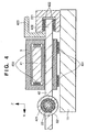
- FIGs. 1 to 4 are schematic views showing an example of a moving/guiding apparatus according to the first embodiment of the present invention, in which Fig. 1 is a perspective view, Fig. 2 is a lower surface view of the moving/guiding apparatus of Fig. 1 from which a main body surface plate is removed, Fig. 3 is a sectional view taken along the line A - A of Fig. 1 , and Fig. 4 is a sectional view taken along the line B - B of Fig. 1 . In the sectional view taken along the line B - B of this embodiment, a pre-pressurizing mechanism is not used.
- the vacuum container (8) is shown in only Fig. 8 , and is omitted in other drawings in order to avoid complexity in the drawings.
- reference numeral 1 denotes a surface plate; 11, a stage surface plate; and 12, a main body surface plate.
- Reference numeral 21 denotes an X-direction stationary guide; 22, a Y-direction stationary guide; and 3, an X-Y movable body movable within a plane in the X and Y directions.
- Reference numeral 41 denotes an X-direction movable body which can move the X-Y movable body 3 in the X direction; 42, a Y-direction movable body which can move the X-Y movable body 3 in the Y direction; 511 and 512, X-direction driving linear motors; and 521 and 522, Y-direction driving linear motors.
- Reference numeral 611 denotes a static pressure bearing (radial bearing) for guiding the X-direction movable body 41 in the X direction and restraining it in all directions except for the X direction; 612, static pressure bearings for guiding the X-direction movable body 41 in the horizontal direction parallel to the X-Y plane and restraining it in the vertical direction; 621, a static pressure bearing (radial bearing) for guiding the Y-direction movable body 42 in the Y direction and restraining it in all directions except for the Y direction; 622, a static pressure bearing for guiding the Y-direction movable body 42 in the horizontal direction and restraining it in the vertical direction parallel to the Z direction; 631, vertically restraining static pressure bearings between the X-Y movable body 3 and stage surface plate 11; 632, static pressure bearings for guiding the X-Y movable body 3 in the Y direction while restraining horizontal (X-direction)
- Reference numeral 8 denotes the vacuum container; 911, a driving force transmission rod for a linear motor 511; and 912, a driving force transmission rod for a linear motor 512.
- the driving force transmission rods 911 and 912 transmit driving forces to the X-direction movable body 41 as X-direction transmitting rigid bodies.
- the driving force transmission rod 912 is connected to the X-direction movable body 41 through a connecting plate 413.
- Reference numerals 921 and 922 denote driving force transmission rods for linear motors 521 and 522.
- the driving force transmission rods 921 and 922 transmit driving forces to the Y-direction movable body 42 as Y-direction transmitting rigid bodies.
- the driving force transmission rod 921 is connected to the Y-direction movable body 42 through a connecting plate 423.
- the X-Y movable body 3 floats from the stage surface plate 11.
- the gaps between the side surface of the X-direction movable body 41 and the static pressure bearings 632 are maintained.
- the gaps between the side surface of the Y-direction movable body 42 and the static pressure bearings 641 are maintained.
- static pressure bearings 611, 612, 621, 622, 631, 632, and 641 described above static pressure bearings each with a labyrinth seal structure are preferably used.
- Such a static pressure bearing is described in, e.g., Japanese Patent Laid-Open No. 63-192864 (Patent No. 2587227).
- the above mechanism is accommodated in the vacuum container 8 shown in Fig. 2 .
- the vacuum container 8 is set on the main body surface plate 12, and accommodates the stage surface plate 11, X-direction guides 21 and 211, Y-direction guides 22 and 221, X-Y movable body 3, X-direction movable body 41, Y-direction movable body 42, and static pressure bearings 611, 612, 621, 622, 631, 632, and 641, and the like entirely.
- the driving force transmission rods 911, 912, 921, and 922 can be projected from and retracted in the vacuum container 8.
- the vacuum container 8 has labyrinth seal structures 80 at its boundaries between the inside and outside through which the driving force transmission rods 911, 912, 921, and 922 are respectively projected or retracted.
- a cylinder 81 concentrically projects from the opening of the vacuum container 8 where the driving force transmission rod 911, 912, 921, or 922 extends, and an annular groove is formed in the cylinder 81 so as to surround the corresponding driving force transmission rod, thus forming recesses and projections.
- This groove forms a labyrinth at that portion through which the driving force transmission rod is projected or retracted.
- An external gas entering the vacuum container 8 from the outside is exhausted by a vacuum pump (not shown) from the vacuum container 8 through a plurality of pores formed in the outer wall of the cylinder 81.
- the X-direction movable body 41 moves in the X direction through the transmission rods 911 and 912, to move the X-Y movable body 3 in the X direction through the static pressure bearings 632.
- the Y-direction movable body 42 moves in the Y direction through the transmission rods 921 and 922, to move the X-Y movable body 3 in the Y direction through the static pressure bearings 641.
- the transmission rods 911, 912, 921, and 922 are vacuum-sealed at the boundaries with respect to the vacuum container 8 by the respective labyrinth seal structures 80.
- each of the X- and Y-direction movable bodies 41 and 42 may be driven by one linear motor.
- An ultrasonic motor may be used as the linear motor.
- the moving/guiding apparatus has the following effects.
- the second embodiment of the present invention provides an exposure apparatus using the moving/guiding apparatus described in the first embodiment.
- the exposure apparatus uses the moving/guiding apparatus according to the present invention.
- a high-quality device such as a semiconductor or liquid crystal panel can be manufactured at a high yield by using the exposure apparatus according to this embodiment.
- a manufacturing system for a semiconductor device (a semiconductor chip such as an IC or LSI, a liquid crystal panel, a CCD, a thin film magnetic head, a micromachine, and the like) by using the apparatus according to the present invention (such as the exposure apparatus described in the second embodiment) will be described.
- a manufacturing system for a semiconductor device a semiconductor chip such as an IC or LSI, a liquid crystal panel, a CCD, a thin film magnetic head, a micromachine, and the like
- maintenance and services such as trouble shooting, periodical maintenance, or providing software for a manufacturing apparatus installed at a semiconductor manufacturing factory are performed by utilizing a computer network outside the factory.
- Fig. 6 expresses the entire system seen from a certain angle.
- reference numeral 1101 denotes a business office of a vender (apparatus supplier) which provides a semiconductor device manufacturing apparatus.
- An example of the manufacturing apparatus includes, e.g., semiconductor manufacturing apparatuses for various types of processes used in a semiconductor manufacturing factory, e.g., a pre-process device (a lithography apparatus such as an exposure apparatus, resist processing apparatus, and etching apparatus, a heat-treating apparatus, a film forming apparatus, a planarizing apparatus, and the like) or a post-processing device (assembling apparatus, inspection apparatus, and the like).
- a pre-process device a lithography apparatus such as an exposure apparatus, resist processing apparatus, and etching apparatus, a heat-treating apparatus, a film forming apparatus, a planarizing apparatus, and the like
- a post-processing device assembling apparatus, inspection apparatus, and the like.
- the business office 1101 has a host management system 1108 for providing a maintenance database for the manufacturing apparatus, a plurality of operation terminal computers 1110, and a local area network (LAN) 1109 which connects the host management system 1108 and operation terminal computers 1110 to make up an Intranet or the like.
- the host management system 1108 has a gateway for connecting the LAN 1109 to the Internet 1105 as a network outside the business office, and a security function of limiting an external access.
- Reference numerals 1102 to 1104 denote manufacturing factories of the semiconductor manufacturer as the user of the manufacturing apparatus.
- the manufacturing factories 1102 to 1104 may be factories belonging to different manufacturers, or factories (for example, a pre-processing factory, a post-processing factory, and the like) belonging to one manufacturer.
- Each of the factories 1102 to 1104 has a plurality of manufacturing apparatuses 1106, a local area network (LAN) 1111 for connecting the manufacturing apparatuses 1106 to make up an intranet or the like, and a host management system 1107 serving as a monitoring unit for monitoring the operating states of the respective manufacturing apparatuses 1106.
- LAN local area network
- the host management system 1107 provided in each of the factories 1102 to 1104 has a gateway for connecting the LAN 1111 in each factory to the Internet 1105 as a network outside the factory.
- the LAN 1111 of each factory can access the host management system 1108 of the vender 1101 through the Internet 1105. Access by only those users limited by the security function of the host management system 1108 is allowed.
- the factory informs the vender of status information (e.g., the symptom of a manufacturing apparatus with a trouble) indicating the operating state of each manufacturing apparatus 1106.
- the factory can receive response information (e.g., information designating a remedy against a trouble, or remedy software or data) regarding this notice, and maintenance information such as update software or help information from the vender.
- Data communication between the factories 1102 and 1104 and the vender 1101 and that in the LANs 1111 of the respective factories are done using a communication protocol (TCP/IP) generally used in the Internet.
- TCP/IP communication protocol
- a high-security dedicated line network e.g., ISDN
- the host management system is not limited to one provided by the vender. The user may make up a database and place it on an external network, and the plurality of factories of the user may be allowed to access the database.
- Fig. 7 is an illustration expressing the entire system of this embodiment seen from an angle different from that of Fig. 6 .
- the plurality of user factories each having the manufacturing apparatuses, and the management system of the vender of the manufacturing apparatuses are connected to each other through an external network.
- Information on production management of each factory and at least one manufacturing apparatus are data-communicated through the external network.
- factories each having manufacturing apparatuses of a plurality of venders, and the management systems of the respective venders of the plurality of manufacturing apparatuses are connected to each other through an external network outside the factories.
- the maintenance information on the respective manufacturing apparatuses are data-communicated through the external network. Referring to Fig.
- reference numeral 1201 denotes a manufacturing factory of a manufacturing apparatus user (semiconductor device manufacturer). Manufacturing apparatuses for performing various types of processes, e.g., an exposure apparatus 1202, a resist processing apparatus 1203, and a film formation processing apparatus 1204 are introduced to the manufacturing line of the factory. Although only one manufacturing factory 1201 is illustrated in Fig. 7 , in fact, a plurality of factories form a network in this manner. The apparatuses of each factory are connected to each other through a LAN 1206 to make up an intranet. A host management system 1205 performs the operation management of the manufacturing line.
- a host management system 1205 performs the operation management of the manufacturing line.
- Each business office of the venders (apparatus suppliers), e.g., an exposure apparatus manufacturer 1210, resist processing apparatus manufacturer 1220, or film formation apparatus manufacturer 1230, has a host management system 1211, 1221, or 1231 for remote-control maintenance of the devices that the users supplied.
- the host management system has a maintenance database and a gateway to an external network, as described above.
- the host management system 1205 for managing the respective apparatuses in the manufacturing factory of the user and the management systems 1211, 1221, and 1231 of the venders of the respective apparatuses are connected to each other through the Internet as an external network 1200, or a private line network.
- the manufacturing line stops operation.
- this situation can be quickly coped with by receiving remote-control maintenance from the vender of the device where the trouble occurs through the Internet 1200. Downtime of the manufacturing line can thus be minimized.
- Each manufacturing apparatus set in the semiconductor manufacturing factory has a display, a network interface, and a computer for performing network access software and apparatus operating software stored in a storage.
- the storage is a stored memory, hard disk, or network file server.
- the network access software includes a dedicated or general web browser, and provides a user interface, an example of which is shown in, e.g., Fig. 8 , on the display.
- the operator who manages the manufacturing apparatus in each factory inputs information such as the type of manufacturing apparatus 1401, serial number 1402, subject of trouble 1403, occurrence date 1404, degree of urgency 1405, symptom 1406, remedy 1407, progress 1408, and the like in the enter boxes on the display.
- the input information is transmitted to the maintenance' database through the Internet.
- Appropriate maintenance information corresponding to the transmitted information is sent back from the maintenance database and shown on the display.
- the user interface provided by the web browser realizes hyperlink functions 1410 to 1412, as shown in Fig. 8 .
- the operator can access further detailed information of each item, and download update software to be used for the manufacturing apparatus or operation guide (help information) for reference by the factory operator from the software library of the vender.
- the maintenance information provided by the maintenance database also includes information concerning the present invention described above.
- the software library also provides update software that realizes the present invention.
- Fig. 9 shows the flow of an overall semiconductor device manufacturing process.
- step 1 design circuit
- step 2 fabric mask
- step 3 manufacturing wafer
- step 4 wafer process
- step 5 assembly process
- step 5 post-process
- a semiconductor chip is formed by using the wafer fabricated in step 4, and includes processes such as an assembly process (dicing and bonding) and packaging process (chip encapsulation).
- step 6 inspections such as the operation confirmation test and durability test of the semiconductor device manufactured in step 5 are conducted. After these steps, the semiconductor device is completed, and shipped (step 7).
- the pre-process and post-process are performed at different dedicated factories, and maintenance for these processes is performed in units of factories by the remote-control maintenance system described above. Information on manufacture management and apparatus maintenance is data-communicated between the pre-process factory and post-process factory through the Internet or private line network.
- Fig. 10 shows the detailed flow of the wafer process.
- step 11 oxidation
- step 12 CVD
- step 13 form electrode
- step 14 implant ion
- ions are implanted in the wafer.
- step 15 resist processing
- step 16 exposure
- step 17 developing
- step 18 etching
- the resist is etched except for the developed resist image.
- step 19 (remove resist), an unnecessary resist after etching is removed. These steps are repeated to form multiple circuit patterns on the wafer.
- the maintenance of the manufacturing devices used in the respective steps is performed by the remote-control maintenance system described above, troubles are prevented. Even if a trouble should occur, it can be coped with, and the normal operating condition is restored quickly. The semiconductor device productivity can thus be improved to be higher than that in the prior art.
- the first and second movable bodies (41 and 42) are guided horizontally and vertically by the guides fixed on the surface plate (11).
- the third movable body (3) is guided in the vertical direction by the surface of the surface plate (11), and is guided in the horizontal direction by the side surfaces of the first and second movable bodies.
- the first to third movable bodies are accommodated in the vacuum container (8).
- the first and second movable bodies are driven by actuators fixed outside the vacuum container.
- the driving operation of the third movable body is transmitted through the horizontal guide operations of the first and second movable bodies.
- the first movable body is guided in one side by the guide (21, 611) fixed on the surface plate and retraining in vertical and horizontal directions entirely, and is guided in the other side by the stationary guide (211, 612) restraining only in the vertical direction.
- the second movable body is guided in one side by the guide (22, 621) fixed on the surface plate and restraining in vertical and horizontal directions entirely, and is guided in the other side by the stationary guide (221, 622) restraining only in the vertical direction.
Landscapes
- Physics & Mathematics (AREA)
- General Physics & Mathematics (AREA)
- Health & Medical Sciences (AREA)
- Engineering & Computer Science (AREA)
- Environmental & Geological Engineering (AREA)
- Epidemiology (AREA)
- Public Health (AREA)
- Exposure And Positioning Against Photoresist Photosensitive Materials (AREA)
- Container, Conveyance, Adherence, Positioning, Of Wafer (AREA)
- Electron Beam Exposure (AREA)
- Exposure Of Semiconductors, Excluding Electron Or Ion Beam Exposure (AREA)
Claims (13)
- Bewegungs-/Führungsgerät mit:einem ersten beweglichen Körper (41) und einem zweiten beweglichen Körper (42), die geführt sind, um sich in sich schneidende Richtungen (X, Y) zu bewegen, bei vertikal unterschiedlichen Positionen angeordnet sind und in einer vertikalen Richtung (Z) eingeschränkt sind,ersten und zweiten Betätigungseinrichtungen (511, 512, 521, 522) zum Antreiben der ersten und zweiten beweglichen Körper (41, 42) in die sich schneidenden Richtungen, undeinem dritten beweglichen Körper (3), der geführt ist, um auf einer Oberflächenplatte in einer Bewegungsrichtung (X) des ersten beweglichen Körpers (41) und in einer Bewegungsrichtung (Y) des zweiten beweglichen Körpers (42) bewegbar zu sein, und der in zwei sich schneidende Richtungen bei einem Empfang von Kräften von Führungsoberflächen in einer horizontalen Richtung der ersten und zweiten beweglichen Körper (41, 42) angetrieben wird,gekennzeichnet durch:erste und zweite Radiallager (611, 621) zum Führen einer Seite des ersten beweglichen Körpers (41) bzw. einer Seite des zweiten beweglichen Körpers (42) und zum Einschränken jeweils der ersten und zweiten beweglichen Körper (41, 42) in allen Richtungen mit Ausnahme der bewegbaren Richtung, unddritten und vierten Lagern (612, 622) zum Führen der anderen Seite des ersten beweglichen Körpers (41) bzw. der anderen Seite des zweiten beweglichen Körpers (42) und zum Einschränken der ersten und zweiten beweglichen Körper (41, 42) lediglich in der vertikalen Richtung (Z).
- Gerät nach Anspruch 1, wobei
das Gerät ferner einen Vakuumbehälter (8) zum Unterbringen der ersten, zweiten und dritten beweglichen Körper (41, 42, 3) umfasst, und
die ersten und zweiten Betätigungseinrichtungen (511, 512, 521, 522) außerhalb des Vakuumbehälters (8) gesetzt sind. - Gerät nach Anspruch 1, ferner mit einem statischen Drucklager zum Führen der ersten, zweiten und dritten beweglichen Körper (41, 42, 3).
- Gerät nach Anspruch 1, wobei die ersten und zweiten Betätigungseinrichtungen (511, 512, 521, 522) Ultraschall-Linearmotoren sind.
- Gerät nach Anspruch 2, mit:einem steifen Körper (911, 912, 921, 922) zum Übertragen von Antriebskräften von den ersten und zweiten Betätigungseinrichtungen (511, 512, 521, 522) zu den ersten und zweiten beweglichen Körpern (41, 42), undeiner Dichtung (80) zum Abdichten des steifen Körpers (911, 912, 921, 922) und des Vakuumbehälters (8) mit einer Labyrinthdichtungsstruktur.
- Gerät nach Anspruch 1, wobei
die erste Betätigungseinrichtung (511, 512) ein Paar von Linearmotoren zum Übertragen von Antriebskräften zu zwei Seiten des ersten beweglichen Körpers (41) umfasst, und
die zweite Betätigungseinrichtung (521, 522) ein Paar von Linearmotoren zur Übertragung von Antriebskräften zu zwei Seiten des zweiten beweglichen Körpers (42) umfasst. - Bewegungs-/Führungsverfahren für ein Bewegungs-/Führungsgerät, das erste und zweite bewegliche Körper (41, 42), die geführt sind, um in sich schneidende Richtungen (X, Y) bewegt zu werden, bei vertikal unterschiedlichen Positionen angeordnet sind und in einer vertikalen Richtung (Z) eingeschränkt sind, und einen dritten beweglichen Körper (3) aufweist, der geführt ist, um auf einer Oberflächenplatte in einer Bewegungsrichtung (X) des ersten beweglichen Körpers (41) und in einer Bewegungsrichtung (Y) des zweiten beweglichen Körpers (42) bewegbar zu sein, mit Schritten:zum Antreiben der ersten und zweiten beweglichen Körper (41, 42) durch jeweilige Betätigungseinrichtungen (511, 512, 521, 522) in Richtungen, in die die ersten und zweiten beweglichen Körper (41, 42) geführt sind, undzum Antreiben des dritten beweglichen Körpers (3) in zwei sich schneidende Richtungen durch Kräfte von Führungsoberflächen in einer horizontalen Richtung der ersten und zweiten beweglichen Körper (41, 42),gekennzeichnet durch
ein Führen einer Seite des ersten beweglichen Körpers (41) bzw. einer Seite des zweiten beweglichen Körpers (42) durch erste und zweite Radiallager (611, 621), und ein Einschränken jeweils der ersten und zweiten beweglichen Körper (41, 42) in allen Richtungen mit Ausnahme der bewegbaren Richtung, und
ein Führen der anderen Seite des ersten beweglichen Körpers (41) bzw. der anderen Seite des zweiten beweglichen Körpers (42) durch dritte und vierte Lager (612, 622) und ein Einschränken der ersten und zweiten beweglichen Körper (41, 42) lediglich in der vertikalen Richtung (Z). - Verfahren nach Anspruch 7, wobei
die ersten, zweiten und dritten beweglichen Körper (41, 42, 3) in einem Vakuumbehälter (8) untergebracht sind, wobei die Betätigungseinrichtungen (511, 512, 521, 522) außerhalb des Vakuumbehälters (8) gesetzt sind. - Verfahren nach Anspruch 7, wobei die ersten, zweiten und dritten beweglichen Körper (41, 42, 3) durch ein statisches Drucklager geführt sind.
- Verfahren nach Anspruch 7, wobei die Betätigungseinrichtungen (511, 512, 521, 522) Ultraschall-Linearmotoren verwenden.
- Verfahren nach Anspruch 8, wobei
Kräfte von den Betätigungseinrichtungen (511, 512, 521, 522) zu den ersten und zweiten beweglichen Körpern (41, 42) durch einen steifen Körper (911, 912, 921, 922) übertragen werden, und
der steife Körper (911, 912, 921, 922) und der Vakuumbehälter (8) durch eine Labyrinthdichtungsstruktur (80) abgedichtet sind. - Verfahren nach Anspruch 7, wobei Antriebskräfte zu zwei Seiten des ersten beweglichen Körpers (41) durch ein Paar von Linearmotoren übertragen werden, und Antriebskräfte zu zwei Seiten des zweiten beweglichen Körpers (42) durch ein anderes Paar von Linearmotoren übertragen werden.
- Belichtungsgerät, das das Bewegungs-/Führungsgerät nach Anspruch 1 verwendet.
Priority Applications (1)
| Application Number | Priority Date | Filing Date | Title |
|---|---|---|---|
| EP11170274A EP2375289A3 (de) | 2001-03-09 | 2002-03-06 | Bewegliche/führende Vorrichtung und Belichtungsvorrichtung damit |
Applications Claiming Priority (2)
| Application Number | Priority Date | Filing Date | Title |
|---|---|---|---|
| JP2001066531A JP4612777B2 (ja) | 2001-03-09 | 2001-03-09 | 移動案内装置、それを用いた露光装置及び半導体デバイス製造方法 |
| JP2001066531 | 2001-03-09 |
Related Child Applications (1)
| Application Number | Title | Priority Date | Filing Date |
|---|---|---|---|
| EP11170274.2 Division-Into | 2011-06-17 |
Publications (3)
| Publication Number | Publication Date |
|---|---|
| EP1248152A2 EP1248152A2 (de) | 2002-10-09 |
| EP1248152A3 EP1248152A3 (de) | 2003-12-17 |
| EP1248152B1 true EP1248152B1 (de) | 2012-07-11 |
Family
ID=18925003
Family Applications (2)
| Application Number | Title | Priority Date | Filing Date |
|---|---|---|---|
| EP11170274A Withdrawn EP2375289A3 (de) | 2001-03-09 | 2002-03-06 | Bewegliche/führende Vorrichtung und Belichtungsvorrichtung damit |
| EP02251570A Expired - Lifetime EP1248152B1 (de) | 2001-03-09 | 2002-03-06 | X/Y Tisch und Belichtungsapparat mit einem solchen Tisch |
Family Applications Before (1)
| Application Number | Title | Priority Date | Filing Date |
|---|---|---|---|
| EP11170274A Withdrawn EP2375289A3 (de) | 2001-03-09 | 2002-03-06 | Bewegliche/führende Vorrichtung und Belichtungsvorrichtung damit |
Country Status (4)
| Country | Link |
|---|---|
| US (1) | US7535552B2 (de) |
| EP (2) | EP2375289A3 (de) |
| JP (1) | JP4612777B2 (de) |
| KR (1) | KR100492242B1 (de) |
Families Citing this family (8)
| Publication number | Priority date | Publication date | Assignee | Title |
|---|---|---|---|---|
| JP4612777B2 (ja) | 2001-03-09 | 2011-01-12 | キヤノン株式会社 | 移動案内装置、それを用いた露光装置及び半導体デバイス製造方法 |
| DE60332681D1 (de) | 2002-01-22 | 2010-07-08 | Ebara Corp | Trägerplattevorrichtung |
| JP4500507B2 (ja) * | 2003-05-20 | 2010-07-14 | キヤノン株式会社 | 移動案内装置及びそれを用いた露光装置 |
| JP2006108005A (ja) * | 2004-10-08 | 2006-04-20 | Hitachi High-Technologies Corp | 電子顕微鏡 |
| JP4817702B2 (ja) * | 2005-04-14 | 2011-11-16 | キヤノン株式会社 | 光学装置及びそれを備えた露光装置 |
| DE102008058306B4 (de) * | 2008-11-17 | 2012-03-08 | Fraunhofer-Gesellschaft zur Förderung der angewandten Forschung e.V. | Aerostatisch geführtes Tischsystem für die Vakuumanwendung |
| US20100158645A1 (en) * | 2008-12-23 | 2010-06-24 | Sumitono Heavy Industries, Ltd. | Stage apparatus |
| JP5827827B2 (ja) * | 2010-06-29 | 2015-12-02 | エーエスエムエル ネザーランズ ビー.ブイ. | アクチュエータ |
Family Cites Families (25)
| Publication number | Priority date | Publication date | Assignee | Title |
|---|---|---|---|---|
| US2329521A (en) * | 1942-02-21 | 1943-09-14 | Jr Thomas P Duncan | Conveyer for bombs or the like |
| JPS5741814A (en) | 1980-08-25 | 1982-03-09 | Nippon Kokan Kk <Nkk> | Setting device for rotational speed of roll of rolling mill |
| JPS5761436A (en) | 1980-09-30 | 1982-04-13 | Toshiba Corp | X-y table |
| JPS6023941A (ja) | 1984-06-06 | 1985-02-06 | Hitachi Ltd | バイアスライト装置 |
| DE3620969A1 (de) * | 1985-06-24 | 1987-01-02 | Canon Kk | Praezisionszufuehrmechanismus |
| US4744675A (en) | 1986-01-21 | 1988-05-17 | Canon Kabushiki Kaisha | Moving mechanism |
| JP2587227B2 (ja) | 1987-02-06 | 1997-03-05 | キヤノン株式会社 | 気体軸受装置 |
| JPH01169394A (ja) * | 1987-12-25 | 1989-07-04 | Hitachi Ltd | 真空容器用xyステージ |
| US5040431A (en) | 1988-01-22 | 1991-08-20 | Canon Kabushiki Kaisha | Movement guiding mechanism |
| JP2714502B2 (ja) * | 1991-09-18 | 1998-02-16 | キヤノン株式会社 | 移動ステージ装置 |
| DE4206731C1 (de) | 1992-03-04 | 1993-07-22 | Blaupunkt-Werke Gmbh, 3200 Hildesheim, De | |
| US5786654A (en) | 1995-06-08 | 1998-07-28 | Minolta Co., Ltd. | Movable stage utilizing electromechanical transducer |
| JPH10144603A (ja) * | 1996-11-14 | 1998-05-29 | Canon Inc | ステージ装置およびこれを用いた露光装置 |
| JP3641131B2 (ja) | 1998-04-10 | 2005-04-20 | 日本電子株式会社 | Xyステージ |
| US6457864B1 (en) * | 1998-05-14 | 2002-10-01 | Massachusetts Institute Of Technology | Omni-directional high precision friction drive positioning stage |
| JP2000031007A (ja) * | 1998-07-08 | 2000-01-28 | Nikon Corp | ステージ装置及びそれを用いた光学装置 |
| JP3745167B2 (ja) * | 1998-07-29 | 2006-02-15 | キヤノン株式会社 | ステージ装置、露光装置およびデバイス製造方法ならびにステージ駆動方法 |
| JP3720613B2 (ja) * | 1999-02-03 | 2005-11-30 | キヤノン株式会社 | 位置決め装置、露光装置およびデバイス製造方法ならびに位置決め方法 |
| JP3814453B2 (ja) * | 2000-01-11 | 2006-08-30 | キヤノン株式会社 | 位置決め装置、半導体露光装置およびデバイス製造方法 |
| US6771350B2 (en) * | 2000-02-25 | 2004-08-03 | Nikon Corporation | Exposure apparatus and exposure method capable of controlling illumination distribution |
| JP3622657B2 (ja) * | 2000-09-18 | 2005-02-23 | 株式会社日立製作所 | 空調制御システム |
| US7244932B2 (en) * | 2000-11-02 | 2007-07-17 | Ebara Corporation | Electron beam apparatus and device fabrication method using the electron beam apparatus |
| JP2002170765A (ja) | 2000-12-04 | 2002-06-14 | Nikon Corp | ステージ装置及び露光装置 |
| JP4612777B2 (ja) | 2001-03-09 | 2011-01-12 | キヤノン株式会社 | 移動案内装置、それを用いた露光装置及び半導体デバイス製造方法 |
| US20100282753A1 (en) | 2009-05-05 | 2010-11-11 | Eaton Corporation | Releasing pressurized fluid from a vessel |
-
2001
- 2001-03-09 JP JP2001066531A patent/JP4612777B2/ja not_active Expired - Fee Related
-
2002
- 2002-03-05 US US10/090,163 patent/US7535552B2/en not_active Expired - Fee Related
- 2002-03-06 EP EP11170274A patent/EP2375289A3/de not_active Withdrawn
- 2002-03-06 EP EP02251570A patent/EP1248152B1/de not_active Expired - Lifetime
- 2002-03-08 KR KR10-2002-0012468A patent/KR100492242B1/ko not_active Expired - Fee Related
Also Published As
| Publication number | Publication date |
|---|---|
| JP2002270673A (ja) | 2002-09-20 |
| US20020128733A1 (en) | 2002-09-12 |
| EP2375289A2 (de) | 2011-10-12 |
| EP2375289A3 (de) | 2012-07-04 |
| JP4612777B2 (ja) | 2011-01-12 |
| US7535552B2 (en) | 2009-05-19 |
| EP1248152A2 (de) | 2002-10-09 |
| KR100492242B1 (ko) | 2005-05-31 |
| EP1248152A3 (de) | 2003-12-17 |
| KR20020072234A (ko) | 2002-09-14 |
Similar Documents
| Publication | Publication Date | Title |
|---|---|---|
| US7063192B2 (en) | Active vibration suppression apparatus, control method therefor, and exposure apparatus having active vibration suppression apparatus | |
| JP4474020B2 (ja) | 移動装置及び露光装置 | |
| EP1215805A2 (de) | Linearmotor und diesen nutzende Vorführeinrichtung | |
| EP1235115B1 (de) | Trägerplattevorrichtung und Verfahren zur Bewegungsführung | |
| US7232257B2 (en) | Hydrostatic bearing and stage apparatus using same | |
| JP2003058258A (ja) | 位置決め装置 | |
| JP3826087B2 (ja) | 位置決め装置、荷電粒子線露光装置 | |
| EP1248152B1 (de) | X/Y Tisch und Belichtungsapparat mit einem solchen Tisch | |
| JP3720680B2 (ja) | ステージ装置、露光装置およびデバイス製造方法 | |
| US6658083B2 (en) | Weight compensation apparatus, stage apparatus using the same, and exposure apparatus | |
| US6990386B2 (en) | Moving mechanism and stage system in exposure apparatus | |
| JP3963426B2 (ja) | ステージ装置および露光装置 | |
| JP4366412B2 (ja) | ステージ装置および露光装置 | |
| JP2003303753A (ja) | 移動位置決め装置及びそれを備える露光装置 | |
| JP2002367893A (ja) | 露光装置 | |
| JP2001297974A (ja) | 位置決め装置 | |
| JP2005260183A (ja) | 移動装置及び露光装置 | |
| JP4065505B2 (ja) | 移動体制御装置、移動体制御方法、露光装置並びに露光方法 | |
| JP2001280391A (ja) | クリーンルーム用空圧機器 | |
| JP2001297965A (ja) | ステージ装置及びこれを用いた露光装置並びにデバイス製造方法 | |
| JP2004349289A (ja) | 移動案内装置及びそれを用いた露光装置 | |
| JP2002359177A (ja) | 露光装置 | |
| JP2003318078A (ja) | 移動案内装置 | |
| JP2003314549A (ja) | 静圧軸受装置 |
Legal Events
| Date | Code | Title | Description |
|---|---|---|---|
| PUAI | Public reference made under article 153(3) epc to a published international application that has entered the european phase |
Free format text: ORIGINAL CODE: 0009012 |
|
| AK | Designated contracting states |
Kind code of ref document: A2 Designated state(s): AT BE CH CY DE DK ES FI FR GB GR IE IT LI LU MC NL PT SE TR |
|
| AX | Request for extension of the european patent |
Free format text: AL;LT;LV;MK;RO;SI |
|
| PUAL | Search report despatched |
Free format text: ORIGINAL CODE: 0009013 |
|
| AK | Designated contracting states |
Kind code of ref document: A3 Designated state(s): AT BE CH CY DE DK ES FI FR GB GR IE IT LI LU MC NL PT SE TR |
|
| AX | Request for extension of the european patent |
Extension state: AL LT LV MK RO SI |
|
| 17P | Request for examination filed |
Effective date: 20040510 |
|
| AKX | Designation fees paid |
Designated state(s): DE GB NL |
|
| 17Q | First examination report despatched |
Effective date: 20090619 |
|
| GRAP | Despatch of communication of intention to grant a patent |
Free format text: ORIGINAL CODE: EPIDOSNIGR1 |
|
| RIN1 | Information on inventor provided before grant (corrected) |
Inventor name: SAKINO, SHIGEO |
|
| GRAS | Grant fee paid |
Free format text: ORIGINAL CODE: EPIDOSNIGR3 |
|
| GRAA | (expected) grant |
Free format text: ORIGINAL CODE: 0009210 |
|
| AK | Designated contracting states |
Kind code of ref document: B1 Designated state(s): DE GB NL |
|
| REG | Reference to a national code |
Ref country code: GB Ref legal event code: FG4D |
|
| REG | Reference to a national code |
Ref country code: DE Ref legal event code: R096 Ref document number: 60243279 Country of ref document: DE Effective date: 20120906 |
|
| REG | Reference to a national code |
Ref country code: NL Ref legal event code: T3 |
|
| PLBE | No opposition filed within time limit |
Free format text: ORIGINAL CODE: 0009261 |
|
| STAA | Information on the status of an ep patent application or granted ep patent |
Free format text: STATUS: NO OPPOSITION FILED WITHIN TIME LIMIT |
|
| 26N | No opposition filed |
Effective date: 20130412 |
|
| REG | Reference to a national code |
Ref country code: DE Ref legal event code: R097 Ref document number: 60243279 Country of ref document: DE Effective date: 20130412 |
|
| GBPC | Gb: european patent ceased through non-payment of renewal fee |
Effective date: 20130306 |
|
| PG25 | Lapsed in a contracting state [announced via postgrant information from national office to epo] |
Ref country code: GB Free format text: LAPSE BECAUSE OF NON-PAYMENT OF DUE FEES Effective date: 20130306 |
|
| PGFP | Annual fee paid to national office [announced via postgrant information from national office to epo] |
Ref country code: NL Payment date: 20140317 Year of fee payment: 13 Ref country code: DE Payment date: 20140331 Year of fee payment: 13 |
|
| REG | Reference to a national code |
Ref country code: DE Ref legal event code: R119 Ref document number: 60243279 Country of ref document: DE |
|
| REG | Reference to a national code |
Ref country code: NL Ref legal event code: MM Effective date: 20150401 |
|
| PG25 | Lapsed in a contracting state [announced via postgrant information from national office to epo] |
Ref country code: DE Free format text: LAPSE BECAUSE OF NON-PAYMENT OF DUE FEES Effective date: 20151001 |
|
| PG25 | Lapsed in a contracting state [announced via postgrant information from national office to epo] |
Ref country code: NL Free format text: LAPSE BECAUSE OF NON-PAYMENT OF DUE FEES Effective date: 20150401 |