EP1247576A1 - Structure porteuse de photocatalyseur, procédé pour sa fabrication, et appareil de réactions photocatalytiques - Google Patents
Structure porteuse de photocatalyseur, procédé pour sa fabrication, et appareil de réactions photocatalytiques Download PDFInfo
- Publication number
- EP1247576A1 EP1247576A1 EP20010309187 EP01309187A EP1247576A1 EP 1247576 A1 EP1247576 A1 EP 1247576A1 EP 20010309187 EP20010309187 EP 20010309187 EP 01309187 A EP01309187 A EP 01309187A EP 1247576 A1 EP1247576 A1 EP 1247576A1
- Authority
- EP
- European Patent Office
- Prior art keywords
- photocatalyst
- water
- substrate
- lithium silicate
- ultraviolet rays
- Prior art date
- Legal status (The legal status is an assumption and is not a legal conclusion. Google has not performed a legal analysis and makes no representation as to the accuracy of the status listed.)
- Withdrawn
Links
- 239000011941 photocatalyst Substances 0.000 title claims abstract description 231
- 238000006243 chemical reaction Methods 0.000 title claims description 47
- 238000000034 method Methods 0.000 title claims description 29
- 230000008569 process Effects 0.000 title claims description 19
- 239000000758 substrate Substances 0.000 claims abstract description 64
- PAZHGORSDKKUPI-UHFFFAOYSA-N lithium metasilicate Chemical compound [Li+].[Li+].[O-][Si]([O-])=O PAZHGORSDKKUPI-UHFFFAOYSA-N 0.000 claims abstract description 63
- 229910052912 lithium silicate Inorganic materials 0.000 claims abstract description 63
- 239000010410 layer Substances 0.000 claims abstract description 61
- 239000011241 protective layer Substances 0.000 claims abstract description 41
- GWEVSGVZZGPLCZ-UHFFFAOYSA-N Titan oxide Chemical compound O=[Ti]=O GWEVSGVZZGPLCZ-UHFFFAOYSA-N 0.000 claims abstract description 32
- 238000005507 spraying Methods 0.000 claims abstract description 17
- OGIDPMRJRNCKJF-UHFFFAOYSA-N titanium oxide Inorganic materials [Ti]=O OGIDPMRJRNCKJF-UHFFFAOYSA-N 0.000 claims abstract description 10
- XLYOFNOQVPJJNP-UHFFFAOYSA-N water Substances O XLYOFNOQVPJJNP-UHFFFAOYSA-N 0.000 claims description 99
- 239000003973 paint Substances 0.000 claims description 29
- VYPSYNLAJGMNEJ-UHFFFAOYSA-N Silicium dioxide Chemical compound O=[Si]=O VYPSYNLAJGMNEJ-UHFFFAOYSA-N 0.000 claims description 23
- 239000000839 emulsion Substances 0.000 claims description 22
- 239000002245 particle Substances 0.000 claims description 21
- 239000004115 Sodium Silicate Substances 0.000 claims description 18
- 229920005989 resin Polymers 0.000 claims description 18
- 239000011347 resin Substances 0.000 claims description 18
- NTHWMYGWWRZVTN-UHFFFAOYSA-N sodium silicate Chemical compound [Na+].[Na+].[O-][Si]([O-])=O NTHWMYGWWRZVTN-UHFFFAOYSA-N 0.000 claims description 18
- 229910052911 sodium silicate Inorganic materials 0.000 claims description 18
- 239000000377 silicon dioxide Substances 0.000 claims description 11
- CBENFWSGALASAD-UHFFFAOYSA-N Ozone Chemical compound [O-][O+]=O CBENFWSGALASAD-UHFFFAOYSA-N 0.000 claims description 9
- 235000012239 silicon dioxide Nutrition 0.000 claims description 8
- 230000015572 biosynthetic process Effects 0.000 claims description 7
- 238000007599 discharging Methods 0.000 claims description 7
- 238000002156 mixing Methods 0.000 claims description 6
- FUJCRWPEOMXPAD-UHFFFAOYSA-N lithium oxide Chemical compound [Li+].[Li+].[O-2] FUJCRWPEOMXPAD-UHFFFAOYSA-N 0.000 claims description 5
- 229910001947 lithium oxide Inorganic materials 0.000 claims description 5
- XUCJHNOBJLKZNU-UHFFFAOYSA-M dilithium;hydroxide Chemical compound [Li+].[Li+].[OH-] XUCJHNOBJLKZNU-UHFFFAOYSA-M 0.000 claims description 3
- 238000011282 treatment Methods 0.000 claims description 3
- 238000000354 decomposition reaction Methods 0.000 abstract description 8
- 230000003647 oxidation Effects 0.000 abstract description 7
- 238000007254 oxidation reaction Methods 0.000 abstract description 7
- 239000000126 substance Substances 0.000 description 12
- 230000009471 action Effects 0.000 description 11
- 235000010215 titanium dioxide Nutrition 0.000 description 11
- 238000012360 testing method Methods 0.000 description 9
- 230000000052 comparative effect Effects 0.000 description 8
- 239000000203 mixture Substances 0.000 description 8
- 239000000049 pigment Substances 0.000 description 8
- 229910000831 Steel Inorganic materials 0.000 description 7
- 230000000694 effects Effects 0.000 description 7
- 239000010959 steel Substances 0.000 description 7
- QAOWNCQODCNURD-UHFFFAOYSA-N Sulfuric acid Chemical compound OS(O)(=O)=O QAOWNCQODCNURD-UHFFFAOYSA-N 0.000 description 6
- 230000006866 deterioration Effects 0.000 description 6
- 239000000463 material Substances 0.000 description 6
- 230000001590 oxidative effect Effects 0.000 description 6
- 239000004606 Fillers/Extenders Substances 0.000 description 5
- 239000004372 Polyvinyl alcohol Substances 0.000 description 5
- OUUQCZGPVNCOIJ-UHFFFAOYSA-M Superoxide Chemical class [O-][O] OUUQCZGPVNCOIJ-UHFFFAOYSA-M 0.000 description 5
- QVGXLLKOCUKJST-UHFFFAOYSA-N atomic oxygen Chemical compound [O] QVGXLLKOCUKJST-UHFFFAOYSA-N 0.000 description 5
- 239000011230 binding agent Substances 0.000 description 5
- 230000000249 desinfective effect Effects 0.000 description 5
- MWUXSHHQAYIFBG-UHFFFAOYSA-N nitrogen oxide Inorganic materials O=[N] MWUXSHHQAYIFBG-UHFFFAOYSA-N 0.000 description 5
- 150000002894 organic compounds Chemical class 0.000 description 5
- 239000001301 oxygen Substances 0.000 description 5
- 229910052760 oxygen Inorganic materials 0.000 description 5
- 229920002451 polyvinyl alcohol Polymers 0.000 description 5
- MYMOFIZGZYHOMD-UHFFFAOYSA-N Dioxygen Chemical compound O=O MYMOFIZGZYHOMD-UHFFFAOYSA-N 0.000 description 4
- VEXZGXHMUGYJMC-UHFFFAOYSA-N Hydrochloric acid Chemical compound Cl VEXZGXHMUGYJMC-UHFFFAOYSA-N 0.000 description 4
- PNEYBMLMFCGWSK-UHFFFAOYSA-N aluminium oxide Inorganic materials [O-2].[O-2].[O-2].[Al+3].[Al+3] PNEYBMLMFCGWSK-UHFFFAOYSA-N 0.000 description 4
- 239000011248 coating agent Substances 0.000 description 4
- 238000000576 coating method Methods 0.000 description 4
- 230000007797 corrosion Effects 0.000 description 4
- 238000005260 corrosion Methods 0.000 description 4
- 239000007788 liquid Substances 0.000 description 4
- 238000004519 manufacturing process Methods 0.000 description 4
- 244000005700 microbiome Species 0.000 description 4
- QTBSBXVTEAMEQO-UHFFFAOYSA-N Acetic acid Chemical compound CC(O)=O QTBSBXVTEAMEQO-UHFFFAOYSA-N 0.000 description 3
- 241000894006 Bacteria Species 0.000 description 3
- HEMHJVSKTPXQMS-UHFFFAOYSA-M Sodium hydroxide Chemical compound [OH-].[Na+] HEMHJVSKTPXQMS-UHFFFAOYSA-M 0.000 description 3
- 238000005299 abrasion Methods 0.000 description 3
- NIXOWILDQLNWCW-UHFFFAOYSA-N acrylic acid group Chemical group C(C=C)(=O)O NIXOWILDQLNWCW-UHFFFAOYSA-N 0.000 description 3
- KRKNYBCHXYNGOX-UHFFFAOYSA-N citric acid Chemical compound OC(=O)CC(O)(C(O)=O)CC(O)=O KRKNYBCHXYNGOX-UHFFFAOYSA-N 0.000 description 3
- 238000001914 filtration Methods 0.000 description 3
- -1 for example Substances 0.000 description 3
- 229910052751 metal Inorganic materials 0.000 description 3
- 239000002184 metal Substances 0.000 description 3
- 125000004430 oxygen atom Chemical group O* 0.000 description 3
- 230000001699 photocatalysis Effects 0.000 description 3
- 238000000746 purification Methods 0.000 description 3
- 230000005855 radiation Effects 0.000 description 3
- 238000003980 solgel method Methods 0.000 description 3
- 239000004408 titanium dioxide Substances 0.000 description 3
- ZAMOUSCENKQFHK-UHFFFAOYSA-N Chlorine atom Chemical compound [Cl] ZAMOUSCENKQFHK-UHFFFAOYSA-N 0.000 description 2
- XEEYBQQBJWHFJM-UHFFFAOYSA-N Iron Chemical compound [Fe] XEEYBQQBJWHFJM-UHFFFAOYSA-N 0.000 description 2
- 239000004677 Nylon Substances 0.000 description 2
- 239000002253 acid Substances 0.000 description 2
- 150000007513 acids Chemical class 0.000 description 2
- 230000001070 adhesive effect Effects 0.000 description 2
- 239000003054 catalyst Substances 0.000 description 2
- 239000000460 chlorine Substances 0.000 description 2
- 229910052801 chlorine Inorganic materials 0.000 description 2
- 238000004040 coloring Methods 0.000 description 2
- 239000013078 crystal Substances 0.000 description 2
- 238000001035 drying Methods 0.000 description 2
- 239000007789 gas Substances 0.000 description 2
- JVTAAEKCZFNVCJ-UHFFFAOYSA-N lactic acid Chemical compound CC(O)C(O)=O JVTAAEKCZFNVCJ-UHFFFAOYSA-N 0.000 description 2
- 229920001778 nylon Polymers 0.000 description 2
- 238000011056 performance test Methods 0.000 description 2
- 238000013032 photocatalytic reaction Methods 0.000 description 2
- 238000002360 preparation method Methods 0.000 description 2
- 239000008213 purified water Substances 0.000 description 2
- 238000004659 sterilization and disinfection Methods 0.000 description 2
- 229910052815 sulfur oxide Inorganic materials 0.000 description 2
- 239000011800 void material Substances 0.000 description 2
- RNFJDJUURJAICM-UHFFFAOYSA-N 2,2,4,4,6,6-hexaphenoxy-1,3,5-triaza-2$l^{5},4$l^{5},6$l^{5}-triphosphacyclohexa-1,3,5-triene Chemical compound N=1P(OC=2C=CC=CC=2)(OC=2C=CC=CC=2)=NP(OC=2C=CC=CC=2)(OC=2C=CC=CC=2)=NP=1(OC=1C=CC=CC=1)OC1=CC=CC=C1 RNFJDJUURJAICM-UHFFFAOYSA-N 0.000 description 1
- VZSRBBMJRBPUNF-UHFFFAOYSA-N 2-(2,3-dihydro-1H-inden-2-ylamino)-N-[3-oxo-3-(2,4,6,7-tetrahydrotriazolo[4,5-c]pyridin-5-yl)propyl]pyrimidine-5-carboxamide Chemical compound C1C(CC2=CC=CC=C12)NC1=NC=C(C=N1)C(=O)NCCC(N1CC2=C(CC1)NN=N2)=O VZSRBBMJRBPUNF-UHFFFAOYSA-N 0.000 description 1
- 241000239290 Araneae Species 0.000 description 1
- BVKZGUZCCUSVTD-UHFFFAOYSA-L Carbonate Chemical compound [O-]C([O-])=O BVKZGUZCCUSVTD-UHFFFAOYSA-L 0.000 description 1
- 201000004624 Dermatitis Diseases 0.000 description 1
- 239000000853 adhesive Substances 0.000 description 1
- 239000000809 air pollutant Substances 0.000 description 1
- 231100001243 air pollutant Toxicity 0.000 description 1
- 238000003915 air pollution Methods 0.000 description 1
- 229910052782 aluminium Inorganic materials 0.000 description 1
- XAGFODPZIPBFFR-UHFFFAOYSA-N aluminium Chemical compound [Al] XAGFODPZIPBFFR-UHFFFAOYSA-N 0.000 description 1
- 230000008859 change Effects 0.000 description 1
- 239000013043 chemical agent Substances 0.000 description 1
- 239000003795 chemical substances by application Substances 0.000 description 1
- 238000004140 cleaning Methods 0.000 description 1
- 150000001875 compounds Chemical class 0.000 description 1
- 239000000356 contaminant Substances 0.000 description 1
- 230000007547 defect Effects 0.000 description 1
- 230000003111 delayed effect Effects 0.000 description 1
- 238000004332 deodorization Methods 0.000 description 1
- 230000001877 deodorizing effect Effects 0.000 description 1
- 230000001627 detrimental effect Effects 0.000 description 1
- 238000004090 dissolution Methods 0.000 description 1
- 239000003344 environmental pollutant Substances 0.000 description 1
- 238000011156 evaluation Methods 0.000 description 1
- 230000005284 excitation Effects 0.000 description 1
- 239000010419 fine particle Substances 0.000 description 1
- 239000003063 flame retardant Substances 0.000 description 1
- 239000011521 glass Substances 0.000 description 1
- 238000005469 granulation Methods 0.000 description 1
- 230000003179 granulation Effects 0.000 description 1
- 230000005283 ground state Effects 0.000 description 1
- 125000004435 hydrogen atom Chemical group [H]* 0.000 description 1
- 229910010272 inorganic material Inorganic materials 0.000 description 1
- 239000011147 inorganic material Substances 0.000 description 1
- 229910052742 iron Inorganic materials 0.000 description 1
- JEIPFZHSYJVQDO-UHFFFAOYSA-N iron(III) oxide Inorganic materials O=[Fe]O[Fe]=O JEIPFZHSYJVQDO-UHFFFAOYSA-N 0.000 description 1
- 239000004310 lactic acid Substances 0.000 description 1
- 235000014655 lactic acid Nutrition 0.000 description 1
- 229910052744 lithium Inorganic materials 0.000 description 1
- 235000015250 liver sausages Nutrition 0.000 description 1
- 230000007774 longterm Effects 0.000 description 1
- 238000002844 melting Methods 0.000 description 1
- 230000008018 melting Effects 0.000 description 1
- 229910044991 metal oxide Inorganic materials 0.000 description 1
- 150000004706 metal oxides Chemical class 0.000 description 1
- 150000007522 mineralic acids Chemical class 0.000 description 1
- 239000004570 mortar (masonry) Substances 0.000 description 1
- 239000003921 oil Substances 0.000 description 1
- 231100000719 pollutant Toxicity 0.000 description 1
- 230000037452 priming Effects 0.000 description 1
- 230000009257 reactivity Effects 0.000 description 1
- 230000009467 reduction Effects 0.000 description 1
- 239000002904 solvent Substances 0.000 description 1
- 239000007921 spray Substances 0.000 description 1
- XTQHKBHJIVJGKJ-UHFFFAOYSA-N sulfur monoxide Chemical class S=O XTQHKBHJIVJGKJ-UHFFFAOYSA-N 0.000 description 1
- 239000000057 synthetic resin Substances 0.000 description 1
- 229920003002 synthetic resin Polymers 0.000 description 1
- 238000010998 test method Methods 0.000 description 1
- 239000002341 toxic gas Substances 0.000 description 1
Images


Classifications
-
- B—PERFORMING OPERATIONS; TRANSPORTING
- B01—PHYSICAL OR CHEMICAL PROCESSES OR APPARATUS IN GENERAL
- B01J—CHEMICAL OR PHYSICAL PROCESSES, e.g. CATALYSIS OR COLLOID CHEMISTRY; THEIR RELEVANT APPARATUS
- B01J37/00—Processes, in general, for preparing catalysts; Processes, in general, for activation of catalysts
- B01J37/02—Impregnation, coating or precipitation
- B01J37/0215—Coating
- B01J37/0217—Pretreatment of the substrate before coating
-
- B—PERFORMING OPERATIONS; TRANSPORTING
- B01—PHYSICAL OR CHEMICAL PROCESSES OR APPARATUS IN GENERAL
- B01J—CHEMICAL OR PHYSICAL PROCESSES, e.g. CATALYSIS OR COLLOID CHEMISTRY; THEIR RELEVANT APPARATUS
- B01J19/00—Chemical, physical or physico-chemical processes in general; Their relevant apparatus
- B01J19/08—Processes employing the direct application of electric or wave energy, or particle radiation; Apparatus therefor
- B01J19/12—Processes employing the direct application of electric or wave energy, or particle radiation; Apparatus therefor employing electromagnetic waves
- B01J19/122—Incoherent waves
- B01J19/123—Ultraviolet light
-
- B—PERFORMING OPERATIONS; TRANSPORTING
- B01—PHYSICAL OR CHEMICAL PROCESSES OR APPARATUS IN GENERAL
- B01J—CHEMICAL OR PHYSICAL PROCESSES, e.g. CATALYSIS OR COLLOID CHEMISTRY; THEIR RELEVANT APPARATUS
- B01J35/00—Catalysts, in general, characterised by their form or physical properties
- B01J35/30—Catalysts, in general, characterised by their form or physical properties characterised by their physical properties
- B01J35/39—Photocatalytic properties
-
- B—PERFORMING OPERATIONS; TRANSPORTING
- B01—PHYSICAL OR CHEMICAL PROCESSES OR APPARATUS IN GENERAL
- B01J—CHEMICAL OR PHYSICAL PROCESSES, e.g. CATALYSIS OR COLLOID CHEMISTRY; THEIR RELEVANT APPARATUS
- B01J37/00—Processes, in general, for preparing catalysts; Processes, in general, for activation of catalysts
- B01J37/02—Impregnation, coating or precipitation
- B01J37/0215—Coating
- B01J37/0225—Coating of metal substrates
-
- B—PERFORMING OPERATIONS; TRANSPORTING
- B01—PHYSICAL OR CHEMICAL PROCESSES OR APPARATUS IN GENERAL
- B01J—CHEMICAL OR PHYSICAL PROCESSES, e.g. CATALYSIS OR COLLOID CHEMISTRY; THEIR RELEVANT APPARATUS
- B01J37/00—Processes, in general, for preparing catalysts; Processes, in general, for activation of catalysts
- B01J37/02—Impregnation, coating or precipitation
- B01J37/024—Multiple impregnation or coating
- B01J37/0244—Coatings comprising several layers
-
- B—PERFORMING OPERATIONS; TRANSPORTING
- B01—PHYSICAL OR CHEMICAL PROCESSES OR APPARATUS IN GENERAL
- B01J—CHEMICAL OR PHYSICAL PROCESSES, e.g. CATALYSIS OR COLLOID CHEMISTRY; THEIR RELEVANT APPARATUS
- B01J37/00—Processes, in general, for preparing catalysts; Processes, in general, for activation of catalysts
- B01J37/34—Irradiation by, or application of, electric, magnetic or wave energy, e.g. ultrasonic waves ; Ionic sputtering; Flame or plasma spraying; Particle radiation
- B01J37/349—Irradiation by, or application of, electric, magnetic or wave energy, e.g. ultrasonic waves ; Ionic sputtering; Flame or plasma spraying; Particle radiation making use of flames, plasmas or lasers
-
- C—CHEMISTRY; METALLURGY
- C02—TREATMENT OF WATER, WASTE WATER, SEWAGE, OR SLUDGE
- C02F—TREATMENT OF WATER, WASTE WATER, SEWAGE, OR SLUDGE
- C02F1/00—Treatment of water, waste water, or sewage
- C02F1/30—Treatment of water, waste water, or sewage by irradiation
- C02F1/32—Treatment of water, waste water, or sewage by irradiation with ultraviolet light
- C02F1/325—Irradiation devices or lamp constructions
-
- C—CHEMISTRY; METALLURGY
- C02—TREATMENT OF WATER, WASTE WATER, SEWAGE, OR SLUDGE
- C02F—TREATMENT OF WATER, WASTE WATER, SEWAGE, OR SLUDGE
- C02F1/00—Treatment of water, waste water, or sewage
- C02F1/72—Treatment of water, waste water, or sewage by oxidation
- C02F1/725—Treatment of water, waste water, or sewage by oxidation by catalytic oxidation
-
- B—PERFORMING OPERATIONS; TRANSPORTING
- B01—PHYSICAL OR CHEMICAL PROCESSES OR APPARATUS IN GENERAL
- B01J—CHEMICAL OR PHYSICAL PROCESSES, e.g. CATALYSIS OR COLLOID CHEMISTRY; THEIR RELEVANT APPARATUS
- B01J21/00—Catalysts comprising the elements, oxides, or hydroxides of magnesium, boron, aluminium, carbon, silicon, titanium, zirconium, or hafnium
- B01J21/06—Silicon, titanium, zirconium or hafnium; Oxides or hydroxides thereof
- B01J21/063—Titanium; Oxides or hydroxides thereof
-
- B—PERFORMING OPERATIONS; TRANSPORTING
- B01—PHYSICAL OR CHEMICAL PROCESSES OR APPARATUS IN GENERAL
- B01J—CHEMICAL OR PHYSICAL PROCESSES, e.g. CATALYSIS OR COLLOID CHEMISTRY; THEIR RELEVANT APPARATUS
- B01J2219/00—Chemical, physical or physico-chemical processes in general; Their relevant apparatus
- B01J2219/08—Processes employing the direct application of electric or wave energy, or particle radiation; Apparatus therefor
- B01J2219/0873—Materials to be treated
- B01J2219/0877—Liquid
-
- B—PERFORMING OPERATIONS; TRANSPORTING
- B01—PHYSICAL OR CHEMICAL PROCESSES OR APPARATUS IN GENERAL
- B01J—CHEMICAL OR PHYSICAL PROCESSES, e.g. CATALYSIS OR COLLOID CHEMISTRY; THEIR RELEVANT APPARATUS
- B01J2219/00—Chemical, physical or physico-chemical processes in general; Their relevant apparatus
- B01J2219/08—Processes employing the direct application of electric or wave energy, or particle radiation; Apparatus therefor
- B01J2219/0873—Materials to be treated
- B01J2219/0892—Materials to be treated involving catalytically active material
-
- C—CHEMISTRY; METALLURGY
- C02—TREATMENT OF WATER, WASTE WATER, SEWAGE, OR SLUDGE
- C02F—TREATMENT OF WATER, WASTE WATER, SEWAGE, OR SLUDGE
- C02F1/00—Treatment of water, waste water, or sewage
- C02F1/72—Treatment of water, waste water, or sewage by oxidation
- C02F1/78—Treatment of water, waste water, or sewage by oxidation with ozone
-
- C—CHEMISTRY; METALLURGY
- C02—TREATMENT OF WATER, WASTE WATER, SEWAGE, OR SLUDGE
- C02F—TREATMENT OF WATER, WASTE WATER, SEWAGE, OR SLUDGE
- C02F2201/00—Apparatus for treatment of water, waste water or sewage
- C02F2201/32—Details relating to UV-irradiation devices
- C02F2201/322—Lamp arrangement
- C02F2201/3223—Single elongated lamp located on the central axis of a turbular reactor
-
- C—CHEMISTRY; METALLURGY
- C02—TREATMENT OF WATER, WASTE WATER, SEWAGE, OR SLUDGE
- C02F—TREATMENT OF WATER, WASTE WATER, SEWAGE, OR SLUDGE
- C02F2201/00—Apparatus for treatment of water, waste water or sewage
- C02F2201/78—Details relating to ozone treatment devices
- C02F2201/782—Ozone generators
-
- C—CHEMISTRY; METALLURGY
- C02—TREATMENT OF WATER, WASTE WATER, SEWAGE, OR SLUDGE
- C02F—TREATMENT OF WATER, WASTE WATER, SEWAGE, OR SLUDGE
- C02F2305/00—Use of specific compounds during water treatment
- C02F2305/10—Photocatalysts
Definitions
- the present invention relates to a photocatalyst module, a method for producing the photocatalyst module, and a photocatalyst reaction apparatus provided with the photocatalyst module. More specifically, the present invention relates to a photocatalyst module comprising a substrate, a photocatalyst, and a protective layer provided between the substrate and the photocatalyst; a method for producing the photocatalyst module; and a photocatalyst reaction apparatus provided with the photocatalyst module. Further, the present invention relates to a photocatalyst reaction apparatus comprising a water tank having a photocatalyst provided therein.
- a photocatalyst is generally employed in a state of a layer formed on the surface of an object, that is, a substrate for the purpose of oxidizing or decomposing substances which adhered to or contacted with the photocatalyst from the outside or for the purpose of disinfecting microorganisms.
- a substrate for the purpose of oxidizing or decomposing substances which adhered to or contacted with the photocatalyst from the outside or for the purpose of disinfecting microorganisms.
- the photocatalyst reacts with a substrate itself to oxidize or decompose it since the photocatalyst exerts a strong oxidizing action or decomposing action on the substrate.
- a method for forming a layer of a photocatalyst a method wherein an active component (for example, titanium oxide) of a photocatalyst is applied or coated on the surface of a substrate by using a binder is known.
- an active component for example, titanium oxide
- excitation of the photocatalyst becomes weak since a coated film is formed even on the surface of the photocatalyst and thus reduction of the oxygen existing on the surface of the photocatalyst is delayed.
- a photocatalyst is formed into a layer without using a binder so that an exposed surface of the photocatalyst is formed on the surface of a substrate.
- This method is preferable in the aspect of reaction efficiency with the photocatalyst since the more the active component of a photocatalyst is exposed on the surface of a substrate, the more readily the active component receives ultraviolet rays, and thus excitement of the photocatalyst is increased.
- a layer of a photocatalyst is formed, for example, by a flame spray coating method to form an exposed surface of the photocatalyst on the surface of a substrate, minute spaces are produced among the particles of the active component of the photocatalyst in which spaces ultraviolet rays enter to cause problems such as oxidation and decomposition of the substrate.
- An alm of the present invention is to provide a photocatalyst module which exerts a strong action of photocatalyst and has means for preventing oxidation and/or decomposition of a substrate.
- Another aim of the present invention is to provide a process for producing the photocatalyst module described above.
- Still aim object of the present invention is to provide a photocatalyst reaction apparatus used for oxidizing or decomposing substances contained in water and to be decomposed, or used for disinfecting microorganisms contained in water without causing any damages to the apparatus.
- Still another aim of the present invention is to provide a photocatalyst reaction apparatus comprising a water tank on at least a part of the inner wall surface of which tank a photocatalyst is provided through a protective layer, to purify or disinfect water to be treated.
- module means an independent part or unit of such an object as an instrument, apparatus, and the like (including part of or a part of the object), and the term “photocatalyst module” as used hereinafter is intended to mean a unit of the object provided with a photocatalyst or a layer of a photocatalyst on the surface thereof.
- photocatalyst module as used hereinafter means a structure comprising a photocatalyst, a part of an inner wall surface of a reaction apparatus, and a protective layer provided between the photocatalyst and the wall.
- a photocatalyst module of the present invention is first summarized as follows:
- disinfection of water can efficiently be performed by contacting ozone with water to be purified in advance of the irradiation of water with ultraviolet rays in the presence of a photocatalyst.
- Fig. 5 is a schematic drawing for illustrating an example of apparatuses used for treating water and comprising a photocatalyst reaction apparatus of the present invention.
- 1 and 2 are photocatalyst modules
- 11 is a layer of a photocatalyst
- 13 is a substrate
- 15 is a protective layer (coated film of lithium silicate)
- S is a space
- 21 is a reaction tank
- 21A and 21B are reaction tanks used as devices for radiating ultraviolet rays in a water treating apparatus
- 31, 31A and 31B are ultraviolet lamps
- 35 is a wall
- 40 is a pipe
- 41 is a water introducing port
- 43 is a water discharging port
- 45 is a deaerating port
- 50 is an apparatus for treating water
- 51 is a pump
- 52 is a device for taking air and radiating ultraviolet rays
- 53 is a tank for mixing water with ozone and storing the mixture.
- photocatalyst module means a unit of an object provided with (a layer of) a photocatalyst on the surface thereof.
- the photocatalyst module of the present invention comprises as principle components a substrate, a photocatalyst, and a protective layer provided between the substrate and the photocatalyst.
- Material for the substrate is not especially limited, and even a metal or synthetic resin which is easily oxidized or decomposed by the action of a photocatalyst can effectively be used as the material of the substrate for the photocatalyst module of the present invention.
- a metal or synthetic resin which is easily oxidized or decomposed by the action of a photocatalyst can effectively be used as the material of the substrate for the photocatalyst module of the present invention.
- the metal for example, iron and aluminum can be mentioned.
- titanium oxide titanium oxide
- titanium oxide includes that of rutile type, brookite type, and anatase type crystal structure
- titanium oxide comprising that of anatase type crystal structure is preferably used in the present invention.
- the photocatalyst is generally used in a shape of a layer of particles.
- the protective layer is composed of a coated film containing lithium silicate.
- lithium silicates There exist several type of lithium silicates based on the difference in the molar ratio of lithium oxide (Li 2 O) to silicon dioxide (SiO 2 ) (lithium oxide : silicon dioxide) therein, and a lithium silicate in which the molar ratio of lithium oxide to silicon dioxide is 1:3 is preferable since the lithium silicate has a high adhesion strength to the substrate.
- Lithium Silicate #35 trade name of a lithium silicate produced by Japan Chemical Industry, Corp. (Nihon Kagaku Kogyo Kabushiki Kaisha).
- a photocatalyst module of the present invention is desirably produced by forming a film containing lithium silicate on the surface of a substrate and then forming a layer of a photocatalyst on the protective layer.
- the protective layer is a film formed by applying a paint prepared from a vehicle containing preferably 80 to 90 % by weight, more desirably 85 to 90 % by weight of lithium silicate and containing 10 to 20 % by weight, more desirably 10 to 15 % by weight of sodium silicate on the surface of the substrate.
- a paint prepared from a vehicle containing preferably 80 to 90 % by weight, more desirably 85 to 90 % by weight of lithium silicate and containing 10 to 20 % by weight, more desirably 10 to 15 % by weight of sodium silicate on the surface of the substrate.
- a film of lithium silicate has such a defect that whereas a coated film formed of lithium silicate alone is not cracked when the film is very thin, the film is cracked to form cracks in such a shape as of a spider's web in the film when the film has a certain thickness or when an extender pigment is added in the paint. Accordingly, lithium silicate is scarcely used for paint up to now. However, when sodium silicate is added to lithium silicate, occurrence of the cracks can be prevented.
- the upper limit of sodium silicate to be contained in the vehicle is preferably about 20 % by weight.
- the resin emulsion disperses in a coated film containing lithium silicate and sodium silicate in this case to prevent dissolution of the coated film. Accordingly, the film the water resistance of which was increased by the addition of a resin emulsion is whitened from a transparent state, for instance, when immersed in water, but the film is not dissolved in water.
- the aqueous emulsion described above preferably should not be gelatinized under a strong alkaline condition of a pH of around 11 to 12 from the aspect of maintaining long canlife. This is because the vehicle containing lithium silicate and sodium silicate described above becomes a strong alkaline of a pH of around 11 to 12, and many aqueous resin emulsions are gelatinized into a state of a gum (gum-up).
- an acrylic emulsion for example, an acrylic emulsion can be used.
- a resin emulsion available on the market is preferably employed.
- Rika Bond ES-56 trade name of an acrylic emulsion produced by Central Science Industry, Corp. (Chuo Rika Kogyo Kabushiki Kaisha)
- Rika Bond ES-56 trade name of an acrylic emulsion produced by Central Science Industry, Corp. (Chuo Rika Kogyo Kabushiki Kaisha)
- the resin emulsion is preferably added to the vehicle described above in an amount of about 10 % by weight or less, for example, about 0.1 to 10 % by weight, and more desirably about 5 to 10 % by weight.
- the resin emulsion is preferably added in the range described above.
- the vehicle is transformed into a paint by adding an extender pigment such as white alumina into the vehicle while slowly agitating to bring about a state of the vehicle in which lumps of pigment particles do not exist, adding a coloring pigment such as titanium white thereto, and then subjecting the vehicle to a filtration.
- an extender pigment such as white alumina
- a coloring pigment such as titanium white thereto
- a filter medium of about 80 mesh (for example, nylon mesh) is preferably used.
- a film can be formed by applying the paint on the surface of the substrate twice each in an amount of 100 to 150 g/m 2 .
- the thickness of the film is preferably about 0.5 to about 0.75 mm.
- a film can be formed, for instance, by priming a liquid prepared by mixing lithium silicate with water at the ratio of 1:1 on the substrate in an amount of 200 to 300 g/m 2 by using a coating roller, drying the coated film, applying the paint described above thereon in an amount of 150 g/m 2 once (when the paint was applied twice or more, the surface of a coating roller becomes stippling) by a roll coating to form a smooth surface, drying the coated film, and then applying, as a finishing top coat, the paint once more in an amount of 150 g/m 2 for adjusting color.
- the coated film of lithium silicate thus formed has advantages as follows:
- a layer of a photocatalyst on the surface of a protective layer containing lithium silicate can be carried out by a known method, for example, a flame spray coating method or sol-gel method
- the flame spray coating method is preferable from the fact that active components of the photocatalyst can be exposed on the surface thereof.
- a plasma spray coating in the air (APS) plasma spray coating under a low pressure (LPC), or high velocity flame spray coating can be used, but the plasma spray coating in the air (APS) is preferable.
- a layer or film of a photocatalyst is formed, for instance, by a plasma spray coating in the air, particles of the photocatalyst are adjusted to a particle size of about 10 to about 60 ⁇ m, a granulation binder such as polyvinyl alcohol (PVA) is added thereto, and then the mixture is sprayed at a high temperature of 10,000 to 20,000°C. At this time, temperature becomes about 200 to 300°C on the surface of the substance (film of lithium silicate) to which the spray is emitted. While a preferable flying speed of photocatalyst particles to be sprayed is varied according to the size and density of the particles, a speed of about 100 to about 300 m/sec is preferable.
- PVA polyvinyl alcohol
- the thickness of a layer Besides, it is preferable to adjust a layer of a photocatalyst so as to have a bonding (or adhesive) strength of 150 to 400 kg/cm 2 , a void content of 1 to 10 %, and a hardness of about 650 to 800 kg/mm.
- a photocatalyst reaction apparatus of the present invention is provided, in at least a portion in the apparatus, with the photocatalyst module described above.
- a photocatalyst reaction apparatus of the present invention comprises a water tank provided with the photocatalyst module.
- a photocatalyst may be provided through a protective layer containing lithium silicate on at least a part of the inner wall surface of the tank instead of using the photocatalyst module.
- a photocatalyst reaction apparatus of the present invention means not only an apparatus used principally for performing photocatalytic reaction, but also an object (including an instrument, apparatus, facility, and the like) which has a layer of a photocatalyst on its surface for the purpose of decomposing pollutants, controlling pollution, or disinfecting bacteria and thus secondarily exhibits a photocatalytic action, while having another function.
- an object including an instrument, apparatus, facility, and the like
- a water purification apparatus, air-cleaning device, deodorizing device, soundproofing wall of a road, traffic sign, cover of lighting fixtures, outer wall or inner wall of architectures, and tile can be mentioned.
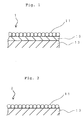
- Fig. 1 is a schematic drawing for illustrating a cross sectional structure of photocatalyst module 1 of the present invention.
- Fig. 2 is a schematic drawing for illustrating a cross sectional structure of conventional photocatalyst module 2.
- Fig. 3 is a schematic drawing for illustrating the state of the surface of a conventional photocatalyst module in which a layer of a photocatalyst is formed by a flame spray coating.
- photocatalyst module 2 in which a layer 11 of photocatalyst particles is formed directly on the surface of substrate 13, for example, a metalic plate, spaces S are inevitably produced among spherical active components (for example, particles of titanium oxide) of a photocatalyst as shown in Fig. 2 and particularly in Fig. 3. Then, ultraviolet rays enter into the spaces S, and thus oxidation or decomposition of the substrate 13 is caused due to the action by the photocatalyst. For instance, when the substrate 13 is a metallic plate, the surface of the substrates gathers rust.
- spherical active components for example, particles of titanium oxide
- film 15 containing inorganic lithium silicate, which is not decomposed by a photocatalyst is provided as a protective layer between substrate 13 and layer 11 of a photocatalyst as shown in Fig. 1, and thus deterioration of the substrate by the action of a photocatalyst can be prevented.
- the film 15 which contains lithium silicate has both a heat resistance and adhesive property, it is possible to subject a photocatalyst to a flame spray coating at a high temperature when layer 11 of a photocatalyst is formed, and the film 15 acts even as binder for increasing the adhesion of the surface of substrate 13 with layer 11 of a photocatalyst.
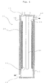
- Fig. 4 is a schematic drawing for illustrating a cross sectional structure of reaction tank 21 in a water purification apparatus which is an example of the photocatalyst reaction apparatuses of the present invention.
- the reaction tank 21 is cylindrical, provided at its center with portion 31 for radiating ultraviolet rays, and provided with layer 11 of a photocatalyst comprising titanium oxide through protective layer (film of lithium silicate) 15 formed on inner wall 35 thereof.
- protective layer 15 film of lithium silicate
- the reaction tank 21 is constructed so that a liquid to be treated (for example, drain water) is flowed from water introducing port 41 into the reaction tank, moved upward in reaction tank 21, and then discharged outside from water discharging port 43.
- a liquid to be treated for example, drain water
- the water to be treated is purified by being irradiated with ultraviolet rays sent from portion 31 for radiating ultraviolet rays and by being subjected to the action of a photocatalyst. That is, ultraviolet rays from portion 31 for radiating ultraviolet rays reach the surface of layer 11 of a photocatalyst, and thus hydroxy radicals and super oxide anions are efficiently formed to decompose or disinfect object substances of the treatment contained in the liquid and contacted to the photocatalyst.
- reaction tank 21 of a water purifying apparatus wall 35 (corresponding to substrate) is generally placed in a condition of being susceptible to the action of photocatalyst since the contact of wall 35 with water is inevitable and the wall continuously receives radiation of ultraviolet rays at certain intensity.
- deterioration in the quality (for example, corrosion) of material of wall 35 can surely be prevented since layer 11 of a photocatalyst and wall 35 are isolated from each other by providing protective layer 15 between them.
- FIG. 5 shows a schematic drawing for illustrating an example of the apparatuse used for treating water and comprising a photocatalyst reaction apparatus of the present invention.
- Apparatus 50 for treating water comprises pump 51 used for introducing water, device 52 for taking air and radiating ultraviolet rays of a short wavelength to the air, tank 53 used both for mixing the water introduced by the pump 51 with the ozone formed in the device 52 described above and for storing the mixture, device 21A for radiating ultraviolet rays of a medium wavelength to the water supplied from tank 53 to disinfect bacteria contained in the water by oxidizing action and to oxidize organic compounds contained in the water to decompose, and device 21B for radiating ultraviolet rays of a long wavelength to the water which passed through device 21A.
- Device 21A for radiating ultraviolet rays of a medium wavelength and device 21B for radiating ultraviolet rays of a long wavelength have basically the same structure as that of the reaction apparatus 21 shown in Fig. 4, and are provided on their inner wall surfaces with protective layers and layers of a photocatalyst as described above.
- ultraviolet rays of a short wavelength for example, 183 to 184 nm (especially 184 nm) are radiated with an ultraviolet lamp into air, and the oxygen molecule (O 2 ) in the air is converted into oxygen atom (O) of ground state and then reacts with surrounding oxygen molecule (O 2 ) to form ozone (O 3 ).
- the ultraviolet lamp comprises a silica glass tube having two electrodes provided therein, and ultraviolet rays of a specific wavelength can be obtained by applying a potential difference between the electrodes.
- the ozone formed in a device for radiating ultraviolet rays of a short wavelength is mixed with water supplied with pump 51, and enters in tank 53. The water which contains ozone and is stored in tank 53 is then introduced into device 21A for radiating ultraviolet rays of a medium wavelength.
- ultraviolet rays of a medium wavelength for example, 254 nm are radiated with ultraviolet lamp 31A.
- the ozone in the water radiated by ultraviolet rays of a medium wavelength is divided into oxygen atom of singlet and oxygen molecule of singlet.
- the active oxygen (oxygen atom of singlet and the like) formed at this stage has a high energy, and thus can disinfect water by its disinfecting action and decompose even chlorine containing organic compounds (for example, trihalomethane) and the like.
- a photocatalyst provided on the inner wall of device 21A for radiating ultraviolet rays of a medium wavelength forms super oxide ion (O 2 - ) and hydroxy radical ( ⁇ OH) from water and dissolved oxygen by being irradiated with ultraviolet rays of a medium wavelength (for example, 254 nm).
- super oxide ion (O 2 - ) and hydroxy radical ( ⁇ OH) have a strong oxidizing power and decompose bacteria and organic compounds.
- the water treated within device 21A for radiating ultraviolet rays of a medium wavelength is discharged from a water discharging port formed at an upper part of the device, passed through pipe 40, and then entered into device 21B for radiating ultraviolet rays of a long wavelength from a lower part of the device 21B.
- the super oxide (O 2 - ) contained in the water becomes oxygen molecule (O 2 ), and hydroxy radical ( ⁇ OH) takes one hydrogen atom (H) from surrounding water (H 2 O) to form active water (H 2 O) thereby to provide purified water by radiating ultraviolet rays of a long wavelength (for example, 310 to 360 nm) with ultraviolet lamp 31B to the active oxygen and the like formed in device 21A for radiating ultraviolet rays of a medium wavelength.
- a long wavelength for example, 310 to 360 nm
- Lithium silicate #35 was weighed, lithium silicate #3 was added thereto, and the resin emulsion shown in Table 1 was slowly added, and the mixture was stirred to form homogeneous vehicles. (In the case of vehicle 1, addition of the resin emulsion was omitted.)
- Coated films formed by applying the paints obtained by the procedures described above on the surface of a substrate were subjected to performance tests according to JIS. The results thus obtained are shown below.
- a paint containing lithium silicate (Paint 2 shown in Table 2) was applied on the surface of a steel pate as substrate twice each in an amount of 100 to 150 g/m 2 by using a coating roller to form a layer of 0.5 to 0.75 mm thick.
- the size of particles of titania (titanium dioxide) was adjusted to about 10 to about 60 ⁇ m and a polyvinyl alcohol (PVA) as a granulating binder was mixed therewith.
- PVA polyvinyl alcohol
- the mixture of the titania particles and PVA was sprayed by a plasma spray coating method in air at a high temperature of 10,000 to 20,000°C to form a layer of titania photocatalyst.
- the thickness of the layer of the photocatalyst thus formed was 0.3 to 0.5 mm.
- the photocatalyst layer had an adhesion strength of 150 to 400 kg/cm 2 , void content of 1 to 10 %, and hardness of 650 to 800 kg/mm.
- the photocatalyst was exposed on its surface, and the photocatalyst module had a high photocatalytic action.
- Example 1 was repeated to obtain a comparative photocatalyst module with the exception that a protective layer containing lithium silicate was not used so that a layer of the photocatalyst was formed directly on the surface of a steel plate.
- Example 1 was repeated to obtain another comparative photocatalyst module with the exception that a protective layer containing lithium silicate was not used so that a layer of the photocatalyst was formed directly on the surface of a steel plate, and that the photocatalyst layer was formed by a sol-gel method under such conditions described below.
- a layer of the photocatalyst was formed such that 1 g of titanium dioxide particles occupied 70 m 2 of the surface of a substrate (steel plate), and the layer was cured at 250 to 600°C for an hour. Besides, the size of the titanium dioxide particles in the sol was 8 to 20 nm.
- the thickness of the photocatalyst layer thus formed was 0.51 to 1.0 mm.
- Example or Comparative Examples On the surface of each of three sample photocatalyst modules obtained in the Example or Comparative Examples, was dropped a testing liquid (10 % sulfuric acid and 10 % hydrochloric acid) by using a dropping pipette, a watch glass was put thereon, and the deterioration of the photocatalyst layer and the surface of the substrate 1 day, 2 days, 3 days, or 1 week after were evaluated by naked eye.
- a testing liquid (10 % sulfuric acid and 10 % hydrochloric acid
- the oxidation or decomposition of a substrate can be prevented by a protective layer provided between the substrate and a layer of a photocatalyst.
- a protective layer containing lithium silicate has a sufficiently high heat resistance, it is possible to form a layer of a photocatalyst by a flame spray coating method in which the temperature of catalyst reaches higher than 1000°C, and a photocatalyst module in which a photocatalyst is exposed to the surface thereof so that the module exhibits a high reactivity can be produced.
Landscapes
- Chemical & Material Sciences (AREA)
- Engineering & Computer Science (AREA)
- Organic Chemistry (AREA)
- Chemical Kinetics & Catalysis (AREA)
- Materials Engineering (AREA)
- Physics & Mathematics (AREA)
- Health & Medical Sciences (AREA)
- Toxicology (AREA)
- Life Sciences & Earth Sciences (AREA)
- Hydrology & Water Resources (AREA)
- Environmental & Geological Engineering (AREA)
- Water Supply & Treatment (AREA)
- General Health & Medical Sciences (AREA)
- Electromagnetism (AREA)
- Optics & Photonics (AREA)
- Plasma & Fusion (AREA)
- Catalysts (AREA)
- Exhaust Gas Treatment By Means Of Catalyst (AREA)
- Paints Or Removers (AREA)
Applications Claiming Priority (2)
| Application Number | Priority Date | Filing Date | Title |
|---|---|---|---|
| JP2001106182 | 2001-04-04 | ||
| JP2001106182A JP2002301378A (ja) | 2001-04-04 | 2001-04-04 | 光触媒モジュール、その製造方法、光触媒反応装置 |
Publications (1)
| Publication Number | Publication Date |
|---|---|
| EP1247576A1 true EP1247576A1 (fr) | 2002-10-09 |
Family
ID=18958733
Family Applications (1)
| Application Number | Title | Priority Date | Filing Date |
|---|---|---|---|
| EP20010309187 Withdrawn EP1247576A1 (fr) | 2001-04-04 | 2001-10-30 | Structure porteuse de photocatalyseur, procédé pour sa fabrication, et appareil de réactions photocatalytiques |
Country Status (4)
| Country | Link |
|---|---|
| US (1) | US6849177B2 (fr) |
| EP (1) | EP1247576A1 (fr) |
| JP (1) | JP2002301378A (fr) |
| CN (1) | CN1378878A (fr) |
Cited By (6)
| Publication number | Priority date | Publication date | Assignee | Title |
|---|---|---|---|---|
| EP1559753A2 (fr) * | 2004-01-22 | 2005-08-03 | Ezio Barucco | Peinture anti-bactérienne à base de silicate de potassium et contenant du dioxyde de titane sous forme anatase. |
| WO2007079749A1 (fr) * | 2006-01-12 | 2007-07-19 | Kass Povl | Procede et systeme pour l’elimination photocatalytique d’halogenes organiques par reduction |
| CN100352562C (zh) * | 2003-05-06 | 2007-12-05 | 株式会社不二机贩 | 光催化剂涂覆方法及该方法制造的光催化剂涂覆成形物 |
| WO2011032900A3 (fr) * | 2009-09-15 | 2011-05-26 | Basf Se | Photoréacteur |
| EP2377609A1 (fr) * | 2010-04-12 | 2011-10-19 | UV-Consulting Peschl e. K. | Réacteur photo-tubulaire modulaire |
| FR2998486A1 (fr) * | 2012-11-28 | 2014-05-30 | Alfaa France | Dispositif de traitement de fluide |
Families Citing this family (16)
| Publication number | Priority date | Publication date | Assignee | Title |
|---|---|---|---|---|
| FR2738813B1 (fr) * | 1995-09-15 | 1997-10-17 | Saint Gobain Vitrage | Substrat a revetement photo-catalytique |
| US6569520B1 (en) * | 2000-03-21 | 2003-05-27 | 3M Innovative Properties Company | Photocatalytic composition and method for preventing algae growth on building materials |
| US7252890B1 (en) | 2004-03-01 | 2007-08-07 | Lockheed Martin Corporation | Anti-contamination coated multi-layer insulation |
| CN101142022B (zh) * | 2005-07-15 | 2011-06-15 | 东芝三菱电机产业系统株式会社 | 光催化材料生产方法和光催化材料生产设备 |
| WO2011159318A1 (fr) * | 2010-06-18 | 2011-12-22 | Empire Technology Development Llc | Capteur comprenant un photocatalyseur |
| JP5569905B2 (ja) * | 2010-09-30 | 2014-08-13 | 大日本塗料株式会社 | 不燃性塗料、不燃性塗膜の形成方法及び不燃性塗膜 |
| US8252238B2 (en) | 2010-11-01 | 2012-08-28 | Empire Technology Development Llc | Air purification system and method for cleaning air |
| US9446352B2 (en) | 2012-11-14 | 2016-09-20 | Toyota Jidosha Kabushiki Kaisha | Atmosphere-cleaning device for vehicles |
| WO2014145916A2 (fr) | 2013-03-15 | 2014-09-18 | Grossman Craig | Appareil de filtration de fluide |
| US10998657B2 (en) * | 2016-03-18 | 2021-05-04 | Apple Inc. | Precious-metal-alloy contacts |
| CN107185561B (zh) * | 2017-06-28 | 2020-05-12 | 贵州大学 | 一种BiOIxBr(1-x)@SiO2光催化剂及其应用 |
| CN108675490B (zh) * | 2018-05-16 | 2021-04-13 | 中节能环保投资发展(江西)有限公司 | 一种工业废水催化反应器 |
| EP3901671A4 (fr) * | 2018-12-21 | 2022-02-23 | Konica Minolta, Inc. | Film multicouche diélectrique, son procédé de production et élément optique utilisant celui-ci |
| CN111482149A (zh) * | 2019-01-25 | 2020-08-04 | 清华大学 | 光催化结构及其制备方法 |
| CN111423038B (zh) * | 2020-03-16 | 2022-04-12 | 沈阳化工大学 | 一种光催化膜分离一体式耦合处理废水装置 |
| JP6923975B1 (ja) * | 2020-10-30 | 2021-08-25 | 有限会社ギムティー | 殺菌部の製造方法及びそれを用いた空気浄化機 |
Citations (10)
| Publication number | Priority date | Publication date | Assignee | Title |
|---|---|---|---|---|
| JPS6035065A (ja) * | 1983-08-04 | 1985-02-22 | Osaka Soda Co Ltd | 海水接触物の防汚方法 |
| US5211990A (en) * | 1991-08-01 | 1993-05-18 | The Dow Chemical Company | Polyolefin flame spraying method |
| JPH05253544A (ja) * | 1992-03-13 | 1993-10-05 | Toto Ltd | 脱臭機能を備えた板状部材の製造方法 |
| JPH07232080A (ja) * | 1993-12-28 | 1995-09-05 | Toto Ltd | 光触媒機能を有する多機能材及びその製造方法 |
| EP0923988A1 (fr) * | 1995-06-19 | 1999-06-23 | Nippon Soda Co., Ltd. | Structure porteuse de photocatalyseur et materiau de revetement photocatalytique |
| US6037289A (en) * | 1995-09-15 | 2000-03-14 | Rhodia Chimie | Titanium dioxide-based photocatalytic coating substrate, and titanium dioxide-based organic dispersions |
| EP1074525A1 (fr) * | 1999-08-05 | 2001-02-07 | Nippon Sheet Glass Co., Ltd. | Article ayant une activité photocatalytique |
| EP1106574A1 (fr) * | 1999-12-10 | 2001-06-13 | Asahi Glass Company Ltd. | Particules de silice en plaquettes et composition les contenant |
| EP1118385A1 (fr) * | 1998-07-30 | 2001-07-25 | Toto Ltd. | Procede de production d'un materiau haute performance a fonction photocatalytique et dispositif y relatif |
| JP2001224966A (ja) * | 2000-02-16 | 2001-08-21 | Ueno Kogyo Kk | 酸化チタン光触媒体及びその製造方法 |
Family Cites Families (8)
| Publication number | Priority date | Publication date | Assignee | Title |
|---|---|---|---|---|
| JPH08318166A (ja) * | 1995-05-25 | 1996-12-03 | Agency Of Ind Science & Technol | 固定化光触媒及び光触媒の固定化方法 |
| US6030526A (en) * | 1996-12-31 | 2000-02-29 | Uv Technologies, Inc. | Water treatment and purification |
| US6136186A (en) * | 1997-01-31 | 2000-10-24 | Lynntech, Inc. | Photocatalytic oxidation of organics using a porous titanium dioxide membrane and an efficient oxidant |
| US6613225B1 (en) * | 1998-06-12 | 2003-09-02 | Kabushiki Kaisha Himeka Engineering | Apparatus for photocatalytic reaction with and method for fixing photocatalyst |
| EP1136527A4 (fr) * | 1998-10-19 | 2003-07-09 | Toto Ltd | Materiau resistant aux salissures, procede et dispositif de production et composition de revetement |
| US6524447B1 (en) * | 1999-11-22 | 2003-02-25 | Titan Technologies | Apparatus and method for photocatalytic purification and disinfection of water and ultrapure water |
| US6569520B1 (en) * | 2000-03-21 | 2003-05-27 | 3M Innovative Properties Company | Photocatalytic composition and method for preventing algae growth on building materials |
| US6447721B1 (en) * | 2000-07-31 | 2002-09-10 | Remotelight, Inc. | Drinking water UV disinfection system and method |
-
2001
- 2001-04-04 JP JP2001106182A patent/JP2002301378A/ja not_active Withdrawn
- 2001-10-30 EP EP20010309187 patent/EP1247576A1/fr not_active Withdrawn
- 2001-11-13 US US10/008,784 patent/US6849177B2/en not_active Expired - Fee Related
- 2001-11-23 CN CN01139416A patent/CN1378878A/zh active Pending
Patent Citations (10)
| Publication number | Priority date | Publication date | Assignee | Title |
|---|---|---|---|---|
| JPS6035065A (ja) * | 1983-08-04 | 1985-02-22 | Osaka Soda Co Ltd | 海水接触物の防汚方法 |
| US5211990A (en) * | 1991-08-01 | 1993-05-18 | The Dow Chemical Company | Polyolefin flame spraying method |
| JPH05253544A (ja) * | 1992-03-13 | 1993-10-05 | Toto Ltd | 脱臭機能を備えた板状部材の製造方法 |
| JPH07232080A (ja) * | 1993-12-28 | 1995-09-05 | Toto Ltd | 光触媒機能を有する多機能材及びその製造方法 |
| EP0923988A1 (fr) * | 1995-06-19 | 1999-06-23 | Nippon Soda Co., Ltd. | Structure porteuse de photocatalyseur et materiau de revetement photocatalytique |
| US6037289A (en) * | 1995-09-15 | 2000-03-14 | Rhodia Chimie | Titanium dioxide-based photocatalytic coating substrate, and titanium dioxide-based organic dispersions |
| EP1118385A1 (fr) * | 1998-07-30 | 2001-07-25 | Toto Ltd. | Procede de production d'un materiau haute performance a fonction photocatalytique et dispositif y relatif |
| EP1074525A1 (fr) * | 1999-08-05 | 2001-02-07 | Nippon Sheet Glass Co., Ltd. | Article ayant une activité photocatalytique |
| EP1106574A1 (fr) * | 1999-12-10 | 2001-06-13 | Asahi Glass Company Ltd. | Particules de silice en plaquettes et composition les contenant |
| JP2001224966A (ja) * | 2000-02-16 | 2001-08-21 | Ueno Kogyo Kk | 酸化チタン光触媒体及びその製造方法 |
Non-Patent Citations (4)
| Title |
|---|
| DATABASE WPI Section Ch Week 198514, Derwent World Patents Index; Class E37, AN 1985-084124, XP002192162 * |
| DATABASE WPI Section Ch Week 199344, Derwent World Patents Index; Class D22, AN 1993-347753, XP002192160 * |
| DATABASE WPI Section Ch Week 199544, Derwent World Patents Index; Class D22, AN 1995-339428, XP002192161 * |
| DATABASE WPI Section Ch Week 200174, Derwent World Patents Index; Class D22, AN 2001-641995, XP002192159 * |
Cited By (9)
| Publication number | Priority date | Publication date | Assignee | Title |
|---|---|---|---|---|
| CN100352562C (zh) * | 2003-05-06 | 2007-12-05 | 株式会社不二机贩 | 光催化剂涂覆方法及该方法制造的光催化剂涂覆成形物 |
| EP1559753A2 (fr) * | 2004-01-22 | 2005-08-03 | Ezio Barucco | Peinture anti-bactérienne à base de silicate de potassium et contenant du dioxyde de titane sous forme anatase. |
| EP1559753A3 (fr) * | 2004-01-22 | 2005-09-07 | Ezio Barucco | Peinture anti-bactérienne à base de silicate de potassium et contenant du dioxyde de titane sous forme anatase. |
| WO2007079749A1 (fr) * | 2006-01-12 | 2007-07-19 | Kass Povl | Procede et systeme pour l’elimination photocatalytique d’halogenes organiques par reduction |
| WO2011032900A3 (fr) * | 2009-09-15 | 2011-05-26 | Basf Se | Photoréacteur |
| US8673157B2 (en) | 2009-09-15 | 2014-03-18 | Basf Se | Photoreactor |
| EP2377609A1 (fr) * | 2010-04-12 | 2011-10-19 | UV-Consulting Peschl e. K. | Réacteur photo-tubulaire modulaire |
| FR2998486A1 (fr) * | 2012-11-28 | 2014-05-30 | Alfaa France | Dispositif de traitement de fluide |
| WO2014083284A1 (fr) * | 2012-11-28 | 2014-06-05 | Alfaa France | Dispositif de traitement d'un fluide à l'aide des rayons ultra-violets |
Also Published As
| Publication number | Publication date |
|---|---|
| CN1378878A (zh) | 2002-11-13 |
| JP2002301378A (ja) | 2002-10-15 |
| US20030039848A1 (en) | 2003-02-27 |
| US6849177B2 (en) | 2005-02-01 |
Similar Documents
| Publication | Publication Date | Title |
|---|---|---|
| US6849177B2 (en) | Photocatalyst reaction apparatus | |
| US7288232B2 (en) | Self-cleaning UV reflective coating | |
| RU2434691C2 (ru) | Объект, покрытый фотокатализатором, и фотокаталитическое жидкое покрытие для него | |
| Ohama et al. | Application of titanium dioxide photocatalysis to construction materials: state-of-the-art report of the RILEM Technical Committee 194-TDP | |
| JP3136612B2 (ja) | 防汚性部材および防汚性コーティング組成物 | |
| US9802841B2 (en) | Method for treating hexavalent chromium-containing aqueous solution | |
| DE69818866T2 (de) | Verwendung einer photokatalysatorzusammensetzung zur entfernung von schädlichen substanzen aus der luft | |
| JP2001269573A (ja) | 光触媒粒子及びその製造方法並びにその用途 | |
| US7858552B2 (en) | Composite catalytic material and process for manufacture of such material | |
| JP3976851B2 (ja) | 二酸化チタン微粒子の製造方法、nox浄化用光触媒粉末の製造方法、塗料の製造方法、建材の製造方法 | |
| JP2001179091A (ja) | 空気浄化用光触媒フィルター | |
| JP2001303276A (ja) | 琺瑯材 | |
| JP4011705B2 (ja) | 光触媒配合物と光触媒含有物並びに光触媒機能発揮材およびその製造方法 | |
| JPH11169727A (ja) | 光触媒体及びその用途 | |
| JPH11343426A (ja) | 光触媒塗料 | |
| CN104768642B (zh) | 光催化剂和光催化剂的制造方法 | |
| JP2001096168A (ja) | 光触媒コーティング及びこのコーティングを有する物品 | |
| JPWO2005026276A1 (ja) | 被膜材 | |
| Gunnarsson | Self cleaning paint: Introduction of photocatalytic particles into a paint system | |
| CN108603049B (zh) | 减少nox的涂层和用其减少nox的方法 | |
| JPH11263660A (ja) | 吹付けコンクリート用セメント組成物 | |
| KR102415590B1 (ko) | 처리수의 자외선 살균장치에 사용되는 방오 코팅제의 제조방법 및 이를 이용한 자외선 살균장치 | |
| Amar | Development of a simple dip coating method for immobilization of TiO2 onto solid supports using direct TiO2 powder | |
| JP2001212902A (ja) | 耐汚染性,脱臭性,大気浄化性に優れた無機塗装金属板及びその製造方法 | |
| US20110104013A1 (en) | Method for producing photocatalytic materials and materials and apparatus therewith |
Legal Events
| Date | Code | Title | Description |
|---|---|---|---|
| PUAI | Public reference made under article 153(3) epc to a published international application that has entered the european phase |
Free format text: ORIGINAL CODE: 0009012 |
|
| AK | Designated contracting states |
Kind code of ref document: A1 Designated state(s): AT BE CH CY DE DK ES FI FR GB GR IE IT LI LU MC NL PT SE TR |
|
| AX | Request for extension of the european patent |
Free format text: AL;LT;LV;MK;RO;SI |
|
| 17P | Request for examination filed |
Effective date: 20030331 |
|
| AKX | Designation fees paid |
Designated state(s): DE GB |
|
| 17Q | First examination report despatched |
Effective date: 20040416 |
|
| STAA | Information on the status of an ep patent application or granted ep patent |
Free format text: STATUS: THE APPLICATION IS DEEMED TO BE WITHDRAWN |
|
| 18D | Application deemed to be withdrawn |
Effective date: 20070501 |