EP1243285B1 - Schlauchverbinder - Google Patents
Schlauchverbinder Download PDFInfo
- Publication number
- EP1243285B1 EP1243285B1 EP00981809A EP00981809A EP1243285B1 EP 1243285 B1 EP1243285 B1 EP 1243285B1 EP 00981809 A EP00981809 A EP 00981809A EP 00981809 A EP00981809 A EP 00981809A EP 1243285 B1 EP1243285 B1 EP 1243285B1
- Authority
- EP
- European Patent Office
- Prior art keywords
- section
- duct
- connector
- main body
- valve disc
- Prior art date
- Legal status (The legal status is an assumption and is not a legal conclusion. Google has not performed a legal analysis and makes no representation as to the accuracy of the status listed.)
- Expired - Lifetime
Links
Images


Classifications
-
- A—HUMAN NECESSITIES
- A61—MEDICAL OR VETERINARY SCIENCE; HYGIENE
- A61M—DEVICES FOR INTRODUCING MEDIA INTO, OR ONTO, THE BODY; DEVICES FOR TRANSDUCING BODY MEDIA OR FOR TAKING MEDIA FROM THE BODY; DEVICES FOR PRODUCING OR ENDING SLEEP OR STUPOR
- A61M39/00—Tubes, tube connectors, tube couplings, valves, access sites or the like, specially adapted for medical use
- A61M39/22—Valves or arrangement of valves
- A61M39/26—Valves closing automatically on disconnecting the line and opening on reconnection thereof
- A61M2039/262—Valves closing automatically on disconnecting the line and opening on reconnection thereof having a fluid space within the valve remaining the same upon connection and disconnection, i.e. neutral-drawback valve
-
- A—HUMAN NECESSITIES
- A61—MEDICAL OR VETERINARY SCIENCE; HYGIENE
- A61M—DEVICES FOR INTRODUCING MEDIA INTO, OR ONTO, THE BODY; DEVICES FOR TRANSDUCING BODY MEDIA OR FOR TAKING MEDIA FROM THE BODY; DEVICES FOR PRODUCING OR ENDING SLEEP OR STUPOR
- A61M39/00—Tubes, tube connectors, tube couplings, valves, access sites or the like, specially adapted for medical use
- A61M39/22—Valves or arrangement of valves
- A61M39/26—Valves closing automatically on disconnecting the line and opening on reconnection thereof
- A61M2039/266—Valves closing automatically on disconnecting the line and opening on reconnection thereof where the valve comprises venting channels, e.g. to insure better connection, to help decreasing the fluid space upon disconnection, or to help the fluid space to remain the same during disconnection
-
- A—HUMAN NECESSITIES
- A61—MEDICAL OR VETERINARY SCIENCE; HYGIENE
- A61M—DEVICES FOR INTRODUCING MEDIA INTO, OR ONTO, THE BODY; DEVICES FOR TRANSDUCING BODY MEDIA OR FOR TAKING MEDIA FROM THE BODY; DEVICES FOR PRODUCING OR ENDING SLEEP OR STUPOR
- A61M39/00—Tubes, tube connectors, tube couplings, valves, access sites or the like, specially adapted for medical use
- A61M39/02—Access sites
-
- Y—GENERAL TAGGING OF NEW TECHNOLOGICAL DEVELOPMENTS; GENERAL TAGGING OF CROSS-SECTIONAL TECHNOLOGIES SPANNING OVER SEVERAL SECTIONS OF THE IPC; TECHNICAL SUBJECTS COVERED BY FORMER USPC CROSS-REFERENCE ART COLLECTIONS [XRACs] AND DIGESTS
- Y10—TECHNICAL SUBJECTS COVERED BY FORMER USPC
- Y10S—TECHNICAL SUBJECTS COVERED BY FORMER USPC CROSS-REFERENCE ART COLLECTIONS [XRACs] AND DIGESTS
- Y10S604/00—Surgery
- Y10S604/905—Aseptic connectors or couplings, e.g. frangible, piercable
Definitions
- the present invention relates to a connector according to the preamble of claim 1 for connecting a duct used in, for example, various medical equipment, fluid infusion containers, and fluid feeding equipment.
- a connector for connecting a duct is provided with a housing and a valve disc made of elastic material and connected to a connecting port of this housing, and is structured so as to be positively connected to the duct by this valve disc.
- the fluid flowing through the duct is fed to the interior of the connector.
- the connector of such type is conventionally known from one disclosed in, for example, JP 9-108361 A.
- This connector is provided with the valve disc having a bellows-like section (bellows section).
- the bellows section of the valve disc shrinks by means of the duct so that an end surface of the valve disc is pushed against the duct.
- the leakage of liquid from a slit of the valve disc is prevented.
- the valve disc shrinks so that a flow path volume of the interior of the valve disc, i.e., the flow path volume of the connector is decreased in comparison with the case where the valve disc is closed, which causes various problems.
- the duct is connected to the connector, and an anticoagulant agent is infused into the catheter from the duct through the connector. Thereafter, when the duct is removed away from the connector, the bellows section of the valve disc is extended so that the flow path volume of the connector is increased. At this time, the blood is sucked into the catheter by a negative pressure.
- the blood is coagulated to cause thrombi within the catheter so that the catheter is clogged and can not be used. For this reason, the catheter has to be removed.
- the number of operations is increased to impose a load to the patient.
- a generic connector is known from US-A-3 788 598.
- a cylindrical connector main body has a flow path in its interior and is opened at both ends.
- a valve disc is disposed at one of opening ends of the connector main body. It is made of elastic material for opening the flow path within the connector main body upon the connection with a duct to be connected to the connector main body and for closing upon the non-connection. The valve disc is opened upon pressure from the duct.
- a cylindrical connecting member is disposed on the outer periphery of the connector main body on a side of the valve disc and coaxially with the connector main body to be movable in an axial direction of the connector main body.
- the duct has a taper outer peripheral surface that decreases gradually in a distal end direction.
- the duct can have a lure lock, and a flange is formed at an end section of the connecting member of the connector. If these are engaged with each other, it is possible to hold the connection more stably.
- the connector 1 according to the present invention is provided with: a substantially cylindrical connector main body 1 having a fluid passage (hereinafter referred to as a flow path) 21 in its interior and opened at both ends (241 and 221); a valve disc 5 disposed at the opening end 221 that is one of the openings of the connector main body 2 and made of elastic material for opening the flow path 21 within the connector main body 2 upon the connection with a duct 6 to be connected to the connector main body 2 and closing upon the non-connection; and a substantially cylindrical duct connecting member 3 disposed on the outer periphery of the connector main body 2 on the side of the valve disc 5 and coaxially with the connector main body 2 to be movable in an axial direction of the connector main body 2.
- a substantially cylindrical connector main body 1 having a fluid passage (hereinafter referred to as a flow path) 21 in its interior and opened at both ends (241 and 221)
- a valve disc 5 disposed at the opening end 221 that is one of the openings of the connector main body 2 and made of
- An inner diameter (diameter of the flow path 21) of the connector main body 2 according to the present invention is usually substantially equal to an outer diameter of a tip end section of the duct 6 to be connected and never greater than the outer diameter. Accordingly, the duct 6 to be connected is no longer substantially inserted into the flow path 21 through the valve disc 5.
- valve disc 5 for example, the left side on the paper surface of Figs. 1 and 2 and Figs. 4 to 9
- proximal end for example, the left side on the paper surface of Figs. 1 and 2 and Figs. 4 to 9
- opening side right side on the paper surface
- distal end with respect to a longitudinal direction (horizontal direction on the paper surface) of the cylindrical connector main body 1.
- the other drawings are based on this rule.
- Fig. 1 is a perspective view showing a state that the duct 6 is not connected to the connector 1.
- Fig. 2 is a sectional perspective view showing a state that the duct 6 is connected thereto.
- the connector 1 connects the duct 6 and has the substantially cylindrical connector main body 2, the substantially cylindrical connecting member 3, a connecting section 4 whereby the connector, main body 2 and the connecting member 3 are connected with each other and the valve disc 5 formed of elastic material (flexible material).
- the connector main body 2 has the flow path 21 in its interior, and the valve disc 5 is disposed at the end of the opening 221 on the side of a proximal end section 22 of the flow path 21.
- a ring-shape retainer section 23 that may be brought into contact with a stepped section 33 of the connecting member 3 to be described later is provided on an outer peripheral surface of the proximal end section 22 of the connector main body 2, and a taper surface 231 that has an outer diameter decreasing gradually from the distal end to the proximal end is formed on the proximal end side of the retainer section 23.
- the taper surface 231 and a taper surface 331 of the stepped section 33 are engaged with each other so that the connecting member 3 is regulated in position and retained at a predetermined position relative to the connector main body 2.
- a taper surface that has an outer diameter decreasing gradually from the proximal end to the distal end is formed on an outer peripheral surface of the distal end section 24 of the connector main body 2; that is, the outer peripheral side of the distal end section 24 is formed into a lure taper-shape.
- the side of the distal end section 24 of the connector main body 2 is formed into a double sleeve shape and has a substantially cylindrical (outer sleeve) lure lock section 25 having a greater diameter than that of the distal end section 24.
- a spiral rib (lure lock screw) 251 is formed in an inner peripheral surface of the lure lock section 25.
- a tube (not shown) having, for example, flexibility and the like are connected liquid-tightly through a predetermined jig or directly on the distal end side of this connector main body 2 whereby the flow path 21 of the connector main body 2 and the inner hole (not shown) of the tube are in communication with each other.
- a tube of an infusion set for example, is given as this tube.
- the distal end section 24 of the connector main body 2 may be inserted into and connected to the tube. Also, the distal end section 24 of the connector main body 2 may be fit to the tube and at the same time, a flange or a lure lock screw (neither shown) on the tube side may be threadedly engaged and locked by the rib 251 of the lure lock section 25.
- the lure lock section 25 may be dispensed with. Also, the outer diameter of the distal end section 24 of the connector main body 2 may be kept constant in the axial direction (longitudinal direction).
- the connector 1 has the connecting member 3 disposed on the outer side of the connector main body 2 and movable in the axial direction of the connector main body 2.
- the connecting member 3 is composed of a proximal end section 31 that is a connecting port section (connecting section) for the duct 6 and a distal end section 32 having a greater diameter than that of the proximal end section 31.
- the duct 6 to be inserted into the connecting member has an outer diameter decreasing gradually toward the distal end.
- the proximal end section 31 has an inner diameter that may allow the insertion length of the duct 6 in which the distal end of the duct 6 pushes and opens the valve disc 5 of the connector main body 2 and maintain the duct 6 stably.
- this proximal end section 31 is smaller than the inner diameter of the distal end section 32, somewhat greater than the outer diameter of the distal end section 24 of the connector main body 2 and smaller than the outer diameter of the retainer section 23 of the connector main body 2.
- the inner diameter of the distal end section 32 is somewhat greater than the outer diameter of the retainer section 23 of the connector main body 2.
- the stepped section 33 is formed at a boundary (boundary section) of the proximal end section 31 and the distal end section 32.
- the taper surface 331 that has an inner diameter decreasing from the distal end to the proximal end is formed on the inner peripheral side of this stepped section 33.
- a position regulating means for regulating the position of the connecting member 3 is defined by this stepped section 33 and the retainer section 23 of the above-described connector main body 2.
- a ring-shape flange 34 is formed on the proximal end of the connecting member 3. This flange 34 is threadedly engaged with the lure lock screw (not shown) on the duct 6 side so that the duct 6 is locked relative to the connecting member 3.
- a spiral rib (lure lock screw) to threadedly engage with the lure lock screw (not shown) on the duct 6 side on the outer peripheral surface of the proximal end section 31 of the connecting member 3.
- the flange 34 of the connecting member 3 or the rib may be dispensed with.
- the connecting member 3 is connected with the connector main body 2 by a connecting section 4.
- the connecting section 4 is constituted of a spiral spring (biasing means) 41 and a ring-shape attaching section 42 formed at a tip end of this spring 41.
- the proximal end of the spring 41 is bonded to a tip end of the above-described connecting member 3, and the attaching section 42 is bounded to a proximal end of the lure lock section 25 of the connector main body 2.
- the spring 41 is set up so as to be extended to some extent from the non-loaded state (natural length) upon the connection between the duct 6 and the connector 1 and biases the connecting member 3 toward the tip end side (in a direction close to the connector main body 2) relative to the connector main body 2, i.e., toward the side of the connector main body 2 by its restoring force (elastic force).
- the valve disc 5 is fixed liquid-tightly (airtightly) to the proximal end opening 221 of the connector main body 2 so as to close the flow path 21.
- a base body section 55 of the valve disc 5 is bonded to the opening 221 end section of the connector main body 2.
- the fitting particularly fitting or threadedly engagement with caulking
- adhesion with adhesives and so on are exemplified.
- the connector main body 2 is made of resin, it is possible to adopt the melt-bonding such as melt-bonding by heat or melt-bonding by ultrasonic wave.
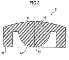
- valve disc 5 is composed of the substantially cylindrical base body section 55 and a pressed section 51 provided to shield the inner hole of the base body section 55 on one end side (proximal end side) in the axial direction of the base body section 55. It is preferable to integrally form the base body section 55 and the pressed section 51.
- the pressed section 51 is a section that receives the pressure from the distal end surface 62 of the duct 6 and its central section is formed into a thick section thicker than the outer periphery.
- This pressed section 51 has a first convex section 52 with which a distal end surface 62 of the duct 6 is brought into contact.
- This first convex section 52 is formed into a substantially dome-shape (conical, bevel, plate-like or the like) and projects by a predetermined amount (is exposed to the connecting port) from the proximal end opening 311 of the connecting member 3 to the outside when the duct 6 is not connected to the connector 1 (joint port).
- the pressed section 51 has a second convex section 53 on the back side of the first convex section 52.
- This second convex section 53 is formed into a substantially hemispherical shape and projects opposite the first convex section 52.
- the pressed section 51 preferably has a curved convex surface on at least one of the surface (surface on the proximal end side) on the side with which the distal end surface 62 of the duct 6 is brought into contact and the surface (surface on the distal end side) on its back side, and more preferably has curved convex surfaces on the surface on the side with which the distal end surface 62 of the duct 6 is brought into contact and the surface on the back side, respectively.
- the liquid-tightness airtightness
- a slit section 54 passing through the pressed section 51 is formed in the central section (thick section) of such a pressed section 51.
- the slit section 54 is comprised of a straight-line cut (slit) formed to pass through the apexes of the first convex section 52 and the second convex section 53.
- This slit section 54 is closed by the elasticity of the pressed section 51 to hold the liquid-tight state (airtight state) in the non-loaded state (the state that the external force is not applied).
- the shape of the slit of the slit section 54 is not limited to that shown in the drawings but may be a cross shape, for example.
- the surface (surface on the distal end side) on the back side to the side, with which the distal end surface 62 of the duct 6 is brought into contact, of the pressed section 51 may be flat (see Fig. 13B).
- the shape of the pressed section 51 is not limited to that shown or described above.
- a relatively small rib is provided to the pressed section 51 or a thickness of the pressed section 51 (section where the slit section 54 is formed) is set up (adjusted) to a suitable value.
- the duct 6 is not connected to the connector 1 (connecting port)
- Examples of the structural materials of the connector main body 2, the connecting member 3, and the connecting section 4 include: polyolefines such as a polyethylene, a polypropylene, an ethylene-propylene copolymer, and an ethylene-vinyl acetate copolymer (EVA); a polyvinyl chloride, a polyvinylidene chloride, a polystyrene, a polyamide, a polyimide, a polyamide imide, a polycarbonate, a poly(4-methylpentene-1), an ionomer , an acrylic resin, a polymethyl methacrylate, an acrylonitrile-butadiene-styrene copolymer (ABS resin), an acrylonitrile-styrene copolymer (AS resin), a butadiene-styrene copolymer; polyesters such as a polyethylene terephthalate (PET), a polybuthylene terephthalate (PBT),
- the connecting member 3 and the connecting section 4 are made of resin, respectively, it is possible to form them into a desired shape with ease by means of, for example, injection molding.
- the valve disc 5 consists of an elastic material (flexible material) which is elastic deformable.
- the material include: various rubber materials such as natural rubber, isoprene rubber, butadiene rubber, styrene-butadiene rubber, nitrile rubber, chloroprene rubber, butyl rubber, acrylic rubber, ethylene-propylene rubber, hydrin rubber, urethane rubber, silicone rubber, and fluorine rubber; various thermoplastic elastomers such as styrene-based, polyolefin-based, polyvinyl chloride-based, polyurethane-based, polyester-based, polyamide-based, polybutadiene-based, trans-polyisoprene-based, fluorine rubber-based, and chlorinated polyethylene-based thermoplastic elastomers. Those materials may be used alone or in combination of at least two of the above-mentioned materials.
- the duct 6 is a section or an equipment to be connected to the connecting port (proximal end section 31 of the connecting member 3) of the connector 1.
- a tubular equipment such as a tip end projecting section (section to which a needle tube is connected) of a syringe (injection syringe) or a hub or sheath that is independent by itself.
- the duct 6 has a flow path 61 in its interior. Then, a taper surface that has an outer diameter decreasing from the proximal end to the distal end is formed on the outer peripheral side of the duct 6. That is, the outer peripheral side of the duct 6 is formed into a lure taper shape.
- the outer diameter of a tip end 63 of the duct 6 is somewhat smaller than the inner diameter (connecting diameter) of the proximal end section 31 of the connecting member 3, and the outer diameter of the proximal end of the duct 6 is greater than the inner diameter of the proximal end section 31.
- the structural material for the duct 6 there can be used the same material as that for the structural material of the connector main body 2, the connecting member 3 and the connecting section 4.
- the connecting member 3 when the duct 6 is not connected to the connector 1 (connecting port) (upon non-connected state), the connecting member 3 is biased toward the tip end side relative to the connector main body 2, i.e., toward the connector main body 2 by the restoring force (elastic force) of the spring 41, and the stepped section 33 of the connecting member 3 is retained by the retainer section 23 of the connector main body 2 whereby the position of the valve disc 5 is regulated (retained) such that the first convex section 52 project to the outside from the proximal end of the connecting member 3 by a predetermined amount.
- first convex section 52 of the valve disc 5 projects to the connecting port upon the non-connected state, it is possible to, for example, clean or wipe the surface of the first convex section 52 of the valve disc 5 to thereby make it possible to keep clean the surface of the first convex section 52.
- the slit section 54 of the valve disc 5 is biased such that the slit section 54 is closed by the elastic force of the pressed section 51 upon the non-connected state, i.e., the non-loaded state (state that the external force is not applied) to thereby keep the closed state and to keep the liquid-tightness (airtightness).
- the duct 6 in this state is moved to the distal end side (in a direction indicated by the arrow in Fig. 1), and is inserted into the connector 1 (connecting member 3) from the opening 311 of the connecting member 3.
- the connecting member 3 is moved in a direction away from the connector main body 2 (proximal end side) against the elastic force of the spring 41.
- the spring 41 is elongated, and the pressed section 51 (first convex section 52) of the valve body 5 is pressed by the distal end surface 62 of the duct 6.
- the first convex section 52 undergoes elastic deformation, a dome shape thereof is gradually changed to a flat shape, and the first convex section 52 is warped (the surface of the pressed section 51 becomes a concave shape).
- the slit section 54 that has been closed gradually opens from the second convex section 53 side, and finally opens at a predetermined opening.
- the flow path 61 of the duct 6 is made to communicate with the flow path 21 of the connector main body 2 (flow path of the connector).
- the duct 6 is connected to the connector 1.
- the duct 6 is fit to the proximal end section 31 at a position where its outer diameter coincides with the inner diameter (diameter of the opening 311) of the proximal end section 31 of the connecting member 3 that is the connecting port.
- the duct 6 is fit to the proximal end section 31 at a position where its outer diameter coincides with the inner diameter (diameter of the opening 311) of the proximal end section 31 of the connecting member 3 that is the connecting port.
- the connecting member 3 moves in a direction away from the connector main body 2.
- the valve disc 5 since it is possible to open the valve disc 5 and make the flow path 61 of the duct 6 communicate with the flow path 21 of the connector main body 2 without invasion of the distal end surface 62 of the duct 6 or the outer peripheral surface of the tip end section into the flow path 21 of the connector main body 2 exceeding the valve disc 5 (without insertion of the duct 6 into the valve disc 5), the volume (flow path volume) of the flow path 21 of the connector main body 2 does not substantially vary before and after the connection of the duct 6 (upon the non-connected state and the connected state).
- the volume of the flow path 21 does not substantially vary in accordance with the opening/closing of the valve disc 5. Also, the distance L from a tip end 63 of the duct 6 to the fluid passage opening 241 (tip end of the flow path 21) does not substantially vary before and after the connection (non-connected state and connected state) of the duct 6 under the state of contact between the tip end 63 of the duct 6 and the valve disc 5.
- the connector 1 is used to be connected to the catheter disposed in the blood vessel, for example, since the volume of the flow path 21 of the connector main body 2 does not substantially vary even if the duct 6 is removed from the connector 1, the blood is no longer sucked into the catheter. Thus, it is possible to prevent (or suppress) the generation of thrombi within the catheter.
- valve disc 5 since the pressure applied to the valve disc 5 by the duct 6 is released, the valve disc 5 is restored back to the original shape immediately by the self-restoring force due to its elasticity and brought into the above-described state shown in Fig. 1.
- the slit section 54 is formed in the first convex section 52 and the second convex section 53 that are the thick sections, it is possible to further enhance the sealability upon the closing of the slit section 54 compared with the case where the slit section 54 is formed in the flat section. It is therefore possible to more positively prevent the liquid leakage against the elevation of the inner pressure of the flow path 21 of the connector main body 2, or the like.
- the connecting member 3 since the connecting member 3 is biased toward the connector main body 2 by the restoring force of the spring 41, when the duct 6 is removed away from the connecting member 3, the connecting member 3 is moved to the distal end relative to the connector main body 2.
- the connecting member 3 since the taper surface 331 is formed on the inner peripheral side of the stepped section 33 of the connecting member 3, the connecting member 3 may smoothly move along the taper surface 331.
- the connecting member 3 is stopped (the connecting member 3 is returned immediately back to the original position). That is, as described above, the stepped section 33 of the connecting member 3 is retained by means of the retainer section 23 of the connector main body 2.
- the connecting member 3 is positioned to the connector main body 2 (valve disc 5) such that the first convex section 52 of the valve disc 5 projects from the proximal end of the connecting member 3 to the outside by a predetermined amount and brought into the above-described state shown in Fig. 1.
- the connector does not have a mode in which the duct 6 is connected so as to pass through the slit section 54 of the valve disc 5 as described above. Accordingly, the slit section 54 is not excessively expanded. As a result, even if the removal of the duct 6 to the connector 1 is repeatedly performed many times, the sealability of the valve disc 5 in the slit section 54 is hardly degraded.
- the connector 1 does not have a mode in which the valve disc 5 is moved within the flow path 21, it is unnecessary to provide a vent hole (through-hole) for making the flow path 21 communicate with the outside. It is thus possible to prevent the contamination of the interior of the flow path 21 of the connector main body 2.
- the connector 1 since the duct 6 is connected directly and used without using a needle, there arises no problem such as erroneous injection by a medial worker and its safety aspect is high.
- the connector 1 it is possible to perform the attachment/detachment of the duct with a slight force, which is superior in operationability.
- the connecting member 3 is adapted to move in the axial direction to the connector main body 2, so that the number of parts may be reduced relatively to thereby make it possible to simplify the structure. Thus, it is possible to reduce the labor in assembling and to reduce the time required for assembling.
- the connector 1 is advantageous of miniaturization. For example, it is possible to apply the connector with ease to the tube in an infusion set, a chemicals feed inlet or the like.
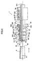
- Fig. 4 is a local sectional view of a side surface of the connector according to the present invention, which shows the state that the duct 6 is not connected to the connector 1 of the second embodiment.
- Fig. 5 is a local sectional view of a side surface, which shows the state that the duct 6 is connected to the connector 1.
- the outer diameter of a proximal end section 551 of the base body section 55 of the valve disc 5 is smaller than the outer diameter of a distal end section 552.
- a stepped section 553 that may retain the distal end section 32 of the connecting member 3 to be described later (that may come into contact with the distal end section 32) is formed at a boundary (boundary section) of the proximal end section 551 and the distal end section 552.
- a taper surface 554 that has an outer diameter decreasing from the distal end to the proximal end is formed on the outer peripheral side of the stepped section 553.
- a ring-shape rib 555 is formed at a tip end of the base body section 55.
- a hole section 556 passing in the axial direction is formed in this rib 555.
- a stepped section is formed in the distal end section 32 of the connecting member 3.
- the taper surface 331 having an inner diameter decreasing from the distal end to the proximal end is formed on the inner peripheral side of this distal end section 32.
- a position regulating means for regulating the position of the connecting member 3 is defined by this distal end section 32 and the stepped section 553 of the valve disc 5.
- the connecting section 4 is constituted of the spiral spring (biasing means) 41 and an engagement claw 43 formed at the tip end of this spring 41.
- the proximal end of the spring 41 is bonded to the tip end of the connecting member 3.
- the tip end section of the spring 41 is inserted into the hole section 556 of the rib 555 of the valve disc 5, and the engagement claw 43 is engaged with the rib 555 under this state to thereby connect the distal end section of the spring 41 to the rib 555 of the valve disc 5.
- valve disc 5 and the connecting member 3 are connected with each other by means of this connecting section 4.
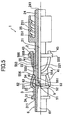
- FIG. 6 is a local sectional view of a side surface, which shows the state that the duct 6 is not connected to the connector 1 of the third embodiment.
- Fig. 7 is a local sectional view of a side surface, which shows the state that the duct 6 is connected to the connector 1.
- the outer diameter of the proximal end section 551 of the base body section 55 of the valve disc 5 is smaller than the outer diameter of the distal end section 552.
- a stepped section 553 that may engage with the stepped section 33 of the connecting member 3 (that may come into abutment against the stepped section 33) is formed at a boundary (boundary section) of this proximal end section 551 and the distal end section 552.
- a taper surface 554 that has an outer diameter decreasing from the distal end to the proximal end is formed on the outer peripheral side of this stepped section 553.
- a position regulating means for regulating the position of the connecting member 3 is defined by this stepped section 553 and the stepped section 33 of the connecting member 3.
- the connecting section 4 is composed of a bellows-like spring (biasing means) 44 and a ring-like attaching section 45 formed at a tip end of this spring 44.
- a ring-like slit 451 passing in the axial direction is formed in this attaching section 45.
- the spring 44 is disposed under the state that it somewhat shrinks from the non-loaded state (natural length) and biases the connecting member 3 toward the tip end side to the connector main body 2 (in a direction closer to the connector main body 2), i.e., toward the connector main body 2 by its restoring force (elastic force).
- a ring-like flange 35 is formed at a tip end of the connecting member 3.
- the spring 44 is located in the interior (inside) of this connecting member 3, and the proximal end of the spring 44 is bonded to the tip end of the valve disc 5.
- the distal end side of the connecting member 3 is inserted into the slit 451 of the attaching section 45 of the connecting section 4 and the rib 35 is engaged with the attaching section 45 under this state whereby the attaching section 45 of the spring 44 and the distal end side of the connecting member 3 are connected with each other.
- the valve disc 5 and the connecting member 3 are connected with each other by means of the connecting section 4.
- valve disc 5 As described in conjunction with the connector 1 according to the above-described first embodiment, also in this connector 1, it is preferable to integrally form the valve disc 5 and the connecting section 4.
- the connecting member 3 When the duct 6 is connected to the connector 1 (connecting port), as shown in Fig. 7, the connecting member 3 is moved in a direction away from the connector main body 2 (toward the proximal end side) so that the spring 44 shrinks.
- the spring 44 of the connecting section 4 is located in the interior of the connecting member 3, it is possible to take any shape for the outer peripheral shape of the connecting member 3. For instance, it is possible to provide a curved surface or a rib (knurl) or the like corresponding to fingers on the outer peripheral side of the connecting member 3 and to perform with ease a device such as facilitating to grip the connector 1. Also, in this connector 1, it is possible to connect the valve disc 5 and the connecting member 3 with each other with ease by means of the connecting section 4 without using adhesive technology or the like, thereby making it possible to assemble the connector 1 with ease.
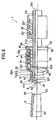
- Fig. 8 is a local sectional view of a side surface, which shows the state that the duct 6 is not connected to the connector 1 of the fourth embodiment.
- Fig. 9 is a local sectional view of a side surface, which shows the state that the duct 6 is connected to the connector 1. Incidentally, the explanation will be omitted for the common points of the connector 1 of the above-described first embodiment and only the main differences will be explained.
- the inner diameter of the proximal end section 551 of the base body section 55 of the valve disc 5 is smaller than the inner diameter of the distal end section 552.
- the connecting section 4 is composed of a step-like spring (biasing means) 46 and a ring-like attaching section 45 formed at a tip end of this spring 46.
- a ring-like slit 451 passing in the axial direction is formed in this attaching section 45.
- the spring 46 is disposed under the state (shrunk state) that a movable section 461 somewhat bends from the non-loaded state and biases the connecting member 3 toward the tip end side to the connector main body 2 (in a direction close to the connector main body 2), i.e., toward the connector main body 2 by its restoring force (elastic force).
- a position regulating means for regulating the position of the connecting member 3 is defined by this movable section 461 of the spring 46 and the stepped section 33 of the connecting member 3.
- the ring-like flange 35 is formed at the tip end of the connecting member 3.
- the spring 46 is located in the interior (inside) of this connecting member 3, and the proximal end of the spring 46 is bonded to a middle part of the proximal end section 551 of the valve disc 5.
- the distal end side of the connecting member 3 is inserted into the slit 451 of the attaching section 45 of the connecting section 4 and the flange 35 is engaged with the attaching section 45 under this state whereby the attaching section 45 of the spring 46 and the distal end side of the connecting member 3 are connected with each other.
- valve disc 5 and the connecting member 3 are connected with each other by means of the connecting section 4.
- valve disc 5 As described in conjunction with the connector 1 according to the above-described first embodiment, also in this connector 1, it is preferable to integrally form the valve disc 5 and the connecting section 4.
- the connecting member 3 When the duct 6 is connected to the connector 1 (connecting port), as shown in Fig. 9, the connecting member 3 is moved in a direction away from the connector main body 2 (toward the proximal end side) so that the movable section 641 of the spring 46 bends toward the connector main body 2 side.
- the spring 46 has the stronger restoring force (restoring force to return the movable section 461 back to the original position) to return to the original state in the initial moving period (state shown in Fig. 8) than in the final moving period (state shown in Fig. 9).
- this connector 1 in comparison with the case of using the biasing means, such as a spiral spring, whose restoring force is increased as it is shrunk and whose restoring force is increased as it is elongated, since it is possible to weaken the restoring force of the spring 46 under the connected state, it is possible to hold the connected state positively by engaging the duct 6 with the proximal end section 31 of the connecting member 3 even if the duct 6 having no lock mechanism is connected to the connector 1.
- the biasing means such as a spiral spring
- the spring 46 of the connecting section 4 is located in the interior of the connecting member 3, it is possible to take any shape for the outer peripheral shape of the connecting member 3. For instance, it is possible to provide a curved surface or a rib (knurl) or the like corresponding to fingers on the outer peripheral side of the connecting member 3 and to perform with ease a device such as facilitating to grip the connector 1.
- this connector 1 it is possible to connect the valve disc 5 and the connecting member 3 with each other with ease by means of the connecting section 4 without using adhesive technology or the like, thereby making it possible to assemble the connector 1 with ease.
- the connector according to the present invention has been described on the basis of the embodiments.
- the present invention is not limited to these. It is possible to replace each structure to any desired structure having the same function.
- valve disc 5 is not limited to each of the embodiments.
- Other structural examples of the valve disc 5 will now be described. Incidentally, for the sake of the explanation, the explanation will be given while regarding the up-and-down direction as an "axial direction", the upper side as a “proximal end” and the lower side as a “distal end” on the paper surface of each sectional view of the valve disc. Also, the common point with the valve disc 5 of the connector 1 according to each embodiment described above will be omitted and only the main differences will be described.
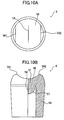
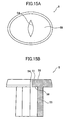
- Fig. 10 corresponds to a plan view showing a structural example of the valve disc 5 (Fig. 10A) and a local sectional view of a side surface (Fig. 10B).
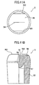
- Fig. 11 shows the valve disc 5 shown in Fig. 10 and corresponds to a plan view (Fig. 11A) and a local sectional view of a side surface (Fig. 11B) when the valve disc 5 is rotated about its center axis by 90 degrees and
- Fig. 12 shows the valve disc 5 shown in Fig. 10 and is a local sectional view of a side surface, which shows the state that the duct 6 is connected thereto.
- the pressed section 51 of this valve disc 5 has a curved concave surface 56 on a surface (surface on the proximal end side) on the side with which the distal end surface 62 of the duct 6 is brought into contact and a curved convex surface 57 on a surface (surface on the distal end side) on its back side.
- the curved concave surface 56 is curved in a direction perpendicular to the slit section 54 and is not curved in the direction in parallel with the slit section 54.
- the shape of the curved concave surface 56 has a shape such as an inner cylindrical peripheral surface with the axis (center axis) in the up-and-down direction in the plan view shown in Fig. 10A.
- a pair of linear apex sections 561 and 562 of this curved concave surface 56 are arranged on both sides through the slit section 54 and in parallel with the slit section 54 in the plan view shown in Figs. 10A and 11A.
- the shape of the curved convex surface 57 forms a substantially spherical surface (shape like a hemispherical surface).
- the slit section 54 is likely to be opened when the pressed section 51 is pressed by means of the duct 6. Namely, the slit section 54 is opened largely.
- the shape of the curved convex surface 57 may be the shape such as a cylindrical peripheral surface, for example.
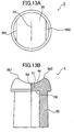
- Fig. 13 corresponds to a plan view (Fig. 13A) showing a structural example of the valve disc 5 and a local sectional view (Fig. 13B) showing its side surface.
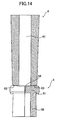
- Fig. 14 shows the valve disc 5 shown in Fig. 13 and is a local sectional view of a side surface, which shows the state that the duct 6 is connected.
- the pressed section 51 of this valve disc 5 has the curved concave surface 56 on a surface (surface on the proximal end side) on the side with which the distal end surface 62 of the duct 6 is brought into contact and a surface (surface on the distal end side) on its back side is flat (flat surface 58).
- the curved concave surface 56 is curved in a direction perpendicular to the slit section 54 and is not curved in the direction in parallel with the slit section 54.
- the shape of the curved concave surface 56 has a shape such as an inner cylindrical peripheral surface with the axis (center axis) in the up-and-down direction in the plan view shown in Fig. 13A.
- the pair of linear apex sections 561 and 562 of this curved concave surface 56 are arranged on both sides through the slit section 54 and in parallel with the slit section 54 in the plan view shown in Fig. 13A.
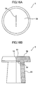
- Fig. 15 is a plan view (A) and a local sectional view (Fig. 15B) of a side surface, which shows still another structural example of the valve disc 5.
- Fig. 16 shows the valve disc 5 shown in Fig. 15 and a plan view (A) and a sectional view (Fig. 16B) of a side surface, which shows the state that the shape of the valve disc 5 is regulated by the connecting member 3.
- the slit section 54 opened under the natural state is formed in the central section of the pressed section 51 of this valve disc 5. This slit section 54 passes through the pressed section 51.
- a contour (contour shape) in a plan view of the pressed section 51 i.e., a contour of the pressed section 51 when the pressed section 51 is projected onto the plan view perpendicular to the axial direction forms an oblong shape (non-circular shape) under the natural state.
- the surface (surface on the proximal end side) of the side with which the distal end surface 62 of the duct 6 contacts and the surface (surface on the distal end side) on the back side thereof of the pressed section 51 are each flat (flat surfaces 59 and 58).
- valve disc 5 When the connector 1 provided with this valve disc 5 is assembled (the valve disc 5 is mounted on the connector 1) and the duct 6 is not connected to the connector 1 (upon the non-connected state), the valve disc 5 is located at the proximal end section 31 of the connecting member 3 (see Fig. 1) and the shape of the valve disc 5 is regulated by this proximal end section 31.
- the contour of the plan view of the pressed section 51 is formed into a substantially circular shape (the same shape as the inner shape of the proximal end section 31) and the slit section 54 is closed.
- valve disc 5 is located at the distal end section 32 of the connecting member 3 (see Fig. 2). Namely, the regulation of the shape of the valve disc 5 by the proximal end section 31 is released.
- the contour in the plan view of the pressed section 51 is returned back to the original shape, i.e., the oblong shape (non-circular shape), and the slit section 54 is opened so that the flow path 61 of the duct 6 and the flow path 21 of the connector main body 2 are in communication with each other through this valve disc 5.
- valve disc 5 may be formed of elastic material of two different kinds of materials in composition or characteristics (flexibility, bending elastic rate, rubber hardness or the like).
- the shape of the slit of the slit section 54 is formed into the straight-line or the cross-shaped.
- the shape is not limited to those but may be formed into, for example an L-shape, an H-shape, a U-shape or the like.
- a plurality of slits may be formed in the slit section 54.
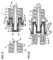
- a fifth embodiment is shown in Figs. 17 and 18 as still another mode of a connector according to the present invention.
- Fig. 17 is a side sectional view showing a state that the connector 1 and the duct 6 are not connected to each other
- Fig. 18 is a side sectional view showing the state that the duct 6 is connected to the connector 1.
- the duct 6 has a lure lock 64 provided with a spiral rib (lure lock screw) 251 on an inner periphery on a tip end section of the duct.
- the duct distal end surface 62 is projected by a predetermined length from a tip end of a section of the lure lock 25.
- the duct 6 Upon the connected state (Fig. 17), the duct 6 is not only connected and fit to the opening 311 of the connecting member 3 but also it is fixed by means of the engagement between the lure lock 64 of the duct 6 and the connecting member 3 (flange 34) of the connector 1.
- the connecting member 3 has the flange 34 and the long taper surface 331 in the stepped section 33.
- the valve disc 5 has the pair of apexes 561 and 562 having the distal end surface 62 formed into the curved concave surface 56 substantially in the same manner as in Fig. 10B in a side sectional view in the vicinity of the pressed section 51 and the curved convex surface 57 on its back surface.
- the rib 555 is provided at a tip end of the base body section 55 of the valve disc 5.
- a convex retainer section 557 is provided on an outer periphery of the base body section 55.
- a notch 558 that may be bent upon depression from the distal end section is provided on a side wall of the base end side from the retainer section 557.
- the slit 54 has a wedge-shaped opening that has the flow path 21 side of the connector main body narrowed in diameter by the bending of the notch 558 due to the depression from the distal end section.
- the connecting section 4 is composed of a spiral spring (biasing means) 41 and a cylindrical attaching section 47 arranged around an axial outer periphery from the distal end of the connector main body 2 to the distal end side in which the lure lock is formed.
- the number of windings of this spring 41 may be higher than that of the spring shown in Fig. 1.
- the attaching section 47 fixes one end of the spring 41 by a groove 471 formed on its distal end side and fixes the rib 555 of the valve disc 5 to the connector main body 2 by a retainer 472 formed at the other end on the proximal end side.
- the valve disc 5 is positively fixed to the connector main body 2.
- the connecting member 3 is slid through a long stroke along the attaching section 47 along a barrel section of the connector main body 2 upon the connection with the duct 6, it is possible to perform the connection smoothly and stably.
- valve disc 5 is held in a predetermined position by the retention of the valve disc 5 to the proximal end side wall by the opening 311 of the connecting member 3 and the retention of the convex retainer section 557 to the taper surface 331 of the connecting member 3.
- Figs. 19 and 20 show a sixth embodiment of a connector according to the present invention.
- Fig. 19 is a side sectional view showing a state that the connector 1 and the duct 6 are not connected to each other
- Fig. 20 is a side sectional view showing the state that the duct 6 is connected to the connector 1.
- valve disc 5 shows a modified mode of the valve disc 5 and the connecting section 4 shown in Fig. 4 and the function of the stepped spring 461 in Fig. 4 is given to the valve disc 5.
- the connector main body 2 has a valve insertion barrel section 26 having a smaller outer diameter on the proximal end side of the proximal end section 22 and the flow path 21 is somewhat expanded on the proximal end surface of the barrel section 26.
- the base body section 55 of the valve disc 5 has a shape to cover the proximal end section 22 including the barrel section 26 of the connector main body 2 and a wing 559 that extends in a double tube shape outwardly from the tip end rib 555 of the base body section 55.
- the tip end section 560 of the wing 559 is pressed and fixed to the intermediate vicinity to the base body section 55 by a proximal end 48 of the connecting section 4 and the tip end section 32 of the connecting member 4 (in the non-connected state).
- a part of the base body section outer periphery of the valve disc 5 is fixed to the connector main body 2 by the ring-like retainer 49.
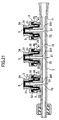
- Fig. 21 shows still another mode of a connector according to the present invention and an example in which a plurality of connectors 1 are arranged in parallel.
- Fig. 21 shows an example in which three connectors are arranged in parallel.
- Each connector 2 has the same structure with the same arrangement as that of each of the valve disc 5, the connecting member 3 and the connecting section 4 shown in Figs. 19 and 20.
- the connecting pipe 7 has a flow path 72 in the interior and has a plurality of openings 73 in the body side wall 72 thereof.
- the connector main body 2 is composed by making one the tip end opening 241 of each connector main body 2 and each opening 73 of the connecting pipe 7 to be continuous with the body side wall 71 of the connecting pipe 7 and to be formed integrally preferably.
- the connector according to the present invention since the volume of the flow path does not substantially vary before and after the connection of the duct, when the duct is detached from and attached to the connector, it is possible to prevent the fluid (liquid, gas or the like) from being accidentally sucked or discharged.
Claims (18)
- Rohrverbinder (1), welcher aufweist:dadurch gekennzeichnet, daßeinen im wesentlichen zylindrischen Hauptkörper (2) mit einem mittigen Durchgangskanal (21) mit offenen Enden (241, 221),eine aus elastischem Material gefertigte Ventilscheibe (5), welche am offenen Ende (221) des Hauptkörpers (2) angeordnet ist, beim Anschließen eines Schlauchs (6) an den Hauptkörper (2) den Durchgangskanal (21) öffnet und beim Entfernen des Schlauchs (6) diesen schließt, wobei die Ventilscheibe durch den Anpreßdruck des Schlauchs (6) geöffnet wird, undein im wesentlichen zylindrisches Verbindungselement (3), welches auf dem mit der Ventilscheibe (5) bestückten Ende des Hauptkörpers (2) koaxial zu diesem angeordnet und auf diesem in axialer Richtung beweglich ist,
die Ventilscheibe (5) sich öffnet, ohne vom Schlauch durchstoßen zu werden, und
das Verbindungselement (3) spannbar ist, um den Schlauch (6) gegen die Ventilscheibe (5) zu ziehen und diesen an den Rohrverbinder anzuschließen. - Schlauchverbinder gemäß Anspruch 1, wobei der Schlauch (6) in die Bohrung (311) des Verbindungselements (3) paßt und von dieser gehalten wird.
- Schlauchverbinder gemäß Anspruch 1 oder 2, wobei eine Schraubenfeder (41), eine Faltfeder (44) oder eine Stufenfeder (46) das Verbindungselement (3) vorgespannt.
- Schlauchverbinder gemäß einem der Ansprüche 1 bis 3, welcher außerdem eine Reguliervorrichtung (461, 553) aufweist, um die Lage des Verbindungselements (3) zu regulieren den am Kanaleingang positionierten Abschnitt der Ventilscheibe (5) freizulegen, wenn kein Schlauch (6) angeschlossen ist.
- Schlauchverbinder gemäß einem der Ansprüche 1 bis 4, wobei die Ventilscheibe (5) einen vorgespannten Abschnitt (51) aufweist und dieser mit einem Schlitz (54) versehen ist, welcher beim Anpressen des Schlauchs (6) geöffnet wird.
- Schlauchverbinder gemäß Anspruch 5, wobei der vorgespannte Abschnitt (51) auf der von der Stirnfläche des Schlauchs (6) berührten Seite oder/und auf der Rückseite eine konvex gekrümmte Fläche hat.
- Schlauchverbinder gemäß Anspruch 5, wobei der vorgespannte Abschnitt (51) auf der von der Stirnfläche des Rohres (6) berührten Seite eine konkav gekrümmte Fläche hat.
- Schlauchverbinder gemäß einem der Ansprüche 5 bis 7, wobei die Rückseite des vorgespannten Abschnitts (51) eben ist.
- Schlauchverbinder gemäß Anspruch 7, wobei die Rückseite des vorgespannten Abschnitts (51) eine konvex gekrümmte Fläche hat.
- Schlauchverbinder gemäß Anspruch 5 oder 6, wobei die von der Stirnfläche des Rohrs (6) berührte Seite des vorgespannten Abschnitts (51) eben ist.
- Schlauchverbinder gemäß einem der Ansprüche 1 bis 4, wobei der vorgespannte Abschnitt (51) der Ventilscheibe (5) einen Schlitz (54) aufweist, welcher im unbelasteten Zustand offen ist, und das Verbindungselement (3) die Ventilscheibe (5) so verformt, daß der Schlitz (54) geschlossen bleibt, wenn kein Schlauch (6) an den Hauptkörper (1) angeschlossen ist.
- Schlauchverbinder gemäß Anspruch 11, wobei der vorgespannte Abschnitts (51) im unbelasteten Zustand nicht kreisförmig ist und die Ventilscheibe (5) vom Verbindungselement (3) im wesentlichen in Kreisform gebracht wird.
- Schlauchverbinder gemäß Anspruch 5, wobei der vorgespannte Abschnitt (51) auf der von der Stirnfläche des Rohres (6) berührten Seite ein erstes konvex gekrümmtes Profil hat.
- Schlauchverbinder gemäß Anspruch 13, wobei das erste konvex gekrümmte Profil im wesentlichen kuppelförmig ist.
- Schlauchverbinder gemäß Anspruch 13 oder 14, wobei der vorgespannte Abschnitt (51) auf der Rückseite ein zweites konvex gekrümmtes Profil hat, welches dem ersten konvex gekrümmten Profil gegenüber sich erstreckt.
- Schlauchverbinder gemäß Anspruch 15, wobei das zweite konvex gekrümmte Profil im wesentlichen Halbkugelform hat.
- Schlauchverbinder gemäß einem der Ansprüche 1 bis 16, wobei beim Anschließen des Schlauchs (6) und somit Öffnen der Ventilscheibe (5) und beim Entfernen des Schlauchs 6) und somit Schließen der Ventilscheibe (5) die Länge des zwischen der Ventilscheibe (5) auf einem Ende des Hauptkörpers und der Öffnung an dessen anderem Ende definierten Durchgangskanals sich im wesentlichen nicht ändert.
- Schlauchverbinder gemäß einem der Ansprüche 1 bis 17, wobei beim Anschließen des Schlauchs (6) an den Hauptkörper (2) und beim Entfernen des Schlauchs (6) von diesem das Volumen des Durchgangskanals (21) sich im wesentlichen nicht ändert.
Applications Claiming Priority (3)
| Application Number | Priority Date | Filing Date | Title |
|---|---|---|---|
| JP35983399 | 1999-12-17 | ||
| JP35983399A JP2001170187A (ja) | 1999-12-17 | 1999-12-17 | コネクタ |
| PCT/JP2000/008964 WO2001043813A1 (fr) | 1999-12-17 | 2000-12-18 | Raccord |
Publications (3)
| Publication Number | Publication Date |
|---|---|
| EP1243285A1 EP1243285A1 (de) | 2002-09-25 |
| EP1243285A4 EP1243285A4 (de) | 2003-03-05 |
| EP1243285B1 true EP1243285B1 (de) | 2005-04-13 |
Family
ID=18466540
Family Applications (1)
| Application Number | Title | Priority Date | Filing Date |
|---|---|---|---|
| EP00981809A Expired - Lifetime EP1243285B1 (de) | 1999-12-17 | 2000-12-18 | Schlauchverbinder |
Country Status (9)
| Country | Link |
|---|---|
| US (1) | US6811139B2 (de) |
| EP (1) | EP1243285B1 (de) |
| JP (1) | JP2001170187A (de) |
| KR (1) | KR100706586B1 (de) |
| CN (1) | CN1217716C (de) |
| AT (1) | ATE292991T1 (de) |
| AU (1) | AU779515B2 (de) |
| DE (1) | DE60019459T2 (de) |
| WO (1) | WO2001043813A1 (de) |
Cited By (9)
| Publication number | Priority date | Publication date | Assignee | Title |
|---|---|---|---|---|
| US7753892B2 (en) | 2001-11-13 | 2010-07-13 | Nypro Inc. | Anti-drawback medical valve |
| US7789864B2 (en) | 1996-11-18 | 2010-09-07 | Nypro Inc. | Luer-activated valve |
| US7837658B2 (en) | 2001-11-13 | 2010-11-23 | Nypro Inc. | Anti-drawback medical valve |
| US7887519B2 (en) | 2005-01-14 | 2011-02-15 | Nypro Inc. | Valve with internal lifter |
| US7914502B2 (en) | 2003-07-31 | 2011-03-29 | Nypro Inc. | Anti-drawback medical valve |
| US8100869B2 (en) | 2006-08-11 | 2012-01-24 | Nypro Inc. | Medical valve with expandable member |
| US8377039B2 (en) | 2002-10-04 | 2013-02-19 | Nxstage Medical, Inc. | Injection site for male luer or other tubular connector |
| US8568371B2 (en) | 2009-06-22 | 2013-10-29 | Np Medical Inc. | Medical valve with improved back-pressure sealing |
| US10668264B2 (en) | 2013-12-20 | 2020-06-02 | Microvention, Inc. | Delivery adapter |
Families Citing this family (36)
| Publication number | Priority date | Publication date | Assignee | Title |
|---|---|---|---|---|
| US20080154214A1 (en) * | 2006-12-22 | 2008-06-26 | Medrad, Inc. | Flow Based Pressure Isolation and Fluid Delivery System Including Flow Based Pressure Isolation |
| JP4116785B2 (ja) * | 2001-11-14 | 2008-07-09 | テルモ株式会社 | コネクタ |
| ITMI20020819A1 (it) | 2002-04-18 | 2003-10-20 | Gambro Lundia Ab | Elemento di connessione e dispositivo di collegamento per tubazioni ad uso medicale |
| JP4000125B2 (ja) * | 2002-08-06 | 2007-10-31 | フカイ工業株式会社 | 注射器接続ポート |
| GB0225075D0 (en) * | 2002-10-29 | 2002-12-04 | Smiths Group Plc | Valves |
| JP2004195016A (ja) * | 2002-12-19 | 2004-07-15 | Top:Kk | 継ぎ手装置 |
| US7125396B2 (en) * | 2002-12-30 | 2006-10-24 | Cardinal Health 303, Inc. | Safety catheter system and method |
| US8025646B2 (en) | 2003-01-09 | 2011-09-27 | Fukai Kogyo Kabushiki Kaisha | Seal valve, connection port, mix-feed tube, connection device for liquid infusion circuit, and connection system for liquid infusion circuit that are for medical device |
| EP1468704B1 (de) * | 2003-04-11 | 2007-02-28 | JSR Corporation | Medizinischer Artikel auf Basis von syndiotaktischem 1,2-Polybutadien |
| JP4060247B2 (ja) * | 2003-07-14 | 2008-03-12 | 株式会社大塚製薬工場 | 薬剤容器用の口部材 |
| US7614423B2 (en) * | 2003-11-04 | 2009-11-10 | Terumo Kabushiki Kaisha | Connector |
| US7484529B2 (en) * | 2003-11-04 | 2009-02-03 | Terumo Kabushiki Kaisha | Connector |
| CA2590011A1 (en) * | 2004-12-21 | 2006-06-29 | Universal Technology Corporation Ltd | Valve |
| US20080103484A1 (en) * | 2004-12-22 | 2008-05-01 | Terumo Kabushiki Kaisha | Connector, Tube Assembly, Infusion Tube Set, And Container For Medical Use |
| KR100721702B1 (ko) * | 2005-11-22 | 2007-05-25 | 한국전자통신연구원 | 접착 필름 및 이를 이용한 플렉시블 디스플레이 제조 방법 |
| US7857284B2 (en) | 2006-04-11 | 2010-12-28 | Nypro Inc. | Medical valve with movable member |
| US8221363B2 (en) | 2006-10-18 | 2012-07-17 | Baxter Healthcare S.A. | Luer activated device with valve element under tension |
| US7981090B2 (en) | 2006-10-18 | 2011-07-19 | Baxter International Inc. | Luer activated device |
| US7753338B2 (en) | 2006-10-23 | 2010-07-13 | Baxter International Inc. | Luer activated device with minimal fluid displacement |
| US20080132833A1 (en) * | 2006-11-06 | 2008-06-05 | Becton, Dickinson And Company | Vascular access devices including a tear-resistant septum |
| US20080172006A1 (en) * | 2007-01-15 | 2008-07-17 | Medrad, Inc. | Patency Check Compatible Check Valve And Fluid Delivery System Including The Patency Check Compatible Check Valve |
| JP5183238B2 (ja) * | 2008-02-15 | 2013-04-17 | 富士フイルム株式会社 | ルアーロック型流体コネクタ、内視鏡、及び雌型流体コネクタ |
| US8251346B2 (en) * | 2008-03-04 | 2012-08-28 | Infusion Innovations, Inc. | Devices, assemblies, and methods for controlling fluid flow |
| KR101039283B1 (ko) * | 2008-09-24 | 2011-06-07 | 이종식 | 무대 조명기기의 여닫이 회전시스템 |
| JP6017955B2 (ja) * | 2009-03-22 | 2016-11-09 | エルカム メディカル アグリカルチュラル コーオペラティブ アソシエーション リミテッド | 閉じた雄ルアーコネクター |
| US7955317B2 (en) | 2009-06-30 | 2011-06-07 | Tyco Healthcare Group Lp | Female adaptor for feeding line |
| EP2456355B1 (de) | 2009-07-20 | 2016-09-14 | Optiscan Biomedical Corporation | Einstellbarer steckverbinder und totraumreduzierung dafür |
| US8731639B2 (en) | 2009-07-20 | 2014-05-20 | Optiscan Biomedical Corporation | Adjustable connector, improved fluid flow and reduced clotting risk |
| US9138572B2 (en) | 2010-06-24 | 2015-09-22 | Np Medical Inc. | Medical valve with fluid volume alteration |
| KR101144104B1 (ko) * | 2011-05-30 | 2012-05-25 | 주식회사 경신 | 로킹장치를 구비한 고전압 실드 커넥터 |
| EP2545956A1 (de) * | 2011-07-15 | 2013-01-16 | Becton Dickinson France | Arzneiabgabevorrichtung und Adapter |
| AU2013216019B2 (en) * | 2012-01-31 | 2018-01-25 | Terumo Kabushiki Kaisha | Connector |
| PL3308067T3 (pl) * | 2015-06-10 | 2020-02-28 | Stucchi S.P.A. | Szybkozłączka zabezpieczająca przed odkręceniem |
| EP3631810A1 (de) | 2017-05-26 | 2020-04-08 | Bayer Healthcare LLC | Injektorzustandslogik mit hämodynamischer überwachung |
| KR102156610B1 (ko) | 2019-03-04 | 2020-09-16 | 주식회사 인성메디칼 | 약물 주입용 안전 캡 |
| US20240108874A1 (en) * | 2022-09-29 | 2024-04-04 | Carefusion 303, Inc. | Fluid connector system |
Family Cites Families (16)
| Publication number | Priority date | Publication date | Assignee | Title |
|---|---|---|---|---|
| US3788598A (en) * | 1971-12-27 | 1974-01-29 | Aro Corp | Hose coupler |
| JPS57184300A (en) | 1981-05-08 | 1982-11-12 | Matsushita Electric Ind Co Ltd | Method of mounting part |
| JPS58138265A (ja) | 1982-02-12 | 1983-08-17 | Nissan Motor Co Ltd | 内燃機関用点火装置 |
| JPS5987840U (ja) * | 1982-12-07 | 1984-06-14 | 住友ベークライト株式会社 | ルア−ロツクコネクタ− |
| JPS6045039U (ja) * | 1983-09-06 | 1985-03-29 | テルモ株式会社 | 逆止弁 |
| JPS6186055A (ja) | 1984-10-04 | 1986-05-01 | Kawasaki Steel Corp | 連鋳タンデイツシユ・フラツクスの添加方法 |
| JPS62197347U (de) * | 1986-06-07 | 1987-12-15 | ||
| US4872591A (en) * | 1987-11-19 | 1989-10-10 | Konopka Richard O | Medication dispenser |
| US4842591A (en) * | 1988-01-21 | 1989-06-27 | Luther Ronald B | Connector with one-way septum valve, and assembly |
| JPH0749059B2 (ja) | 1988-10-14 | 1995-05-31 | 株式会社ニッショー | 使用時連通具 |
| US5699821A (en) * | 1993-10-13 | 1997-12-23 | Paradis; Joseph R. | Control of fluid flow |
| NZ286445A (en) | 1995-05-16 | 1997-12-19 | Ivac Corp | Needleless luer connector: deformable piston occludes bore |
| DE19639870C1 (de) | 1996-09-27 | 1997-12-11 | Fresenius Ag | Anschlußstück für Kunststoffkanülen und Venenkatheter |
| US6089541A (en) * | 1998-09-10 | 2000-07-18 | Halkey-Roberts Corporation | Valve having a valve body and a deformable stem therein |
| JP2000014797A (ja) | 1998-07-02 | 2000-01-18 | Jms Co Ltd | 混注ポート |
| US6113068A (en) * | 1998-10-05 | 2000-09-05 | Rymed Technologies | Swabbable needleless injection port system having low reflux |
-
1999
- 1999-12-17 JP JP35983399A patent/JP2001170187A/ja active Pending
-
2000
- 2000-12-18 US US10/168,107 patent/US6811139B2/en not_active Expired - Lifetime
- 2000-12-18 EP EP00981809A patent/EP1243285B1/de not_active Expired - Lifetime
- 2000-12-18 KR KR1020027007757A patent/KR100706586B1/ko not_active IP Right Cessation
- 2000-12-18 WO PCT/JP2000/008964 patent/WO2001043813A1/ja active IP Right Grant
- 2000-12-18 AT AT00981809T patent/ATE292991T1/de not_active IP Right Cessation
- 2000-12-18 CN CN008192766A patent/CN1217716C/zh not_active Expired - Fee Related
- 2000-12-18 DE DE60019459T patent/DE60019459T2/de not_active Expired - Lifetime
- 2000-12-18 AU AU18938/01A patent/AU779515B2/en not_active Ceased
Cited By (13)
| Publication number | Priority date | Publication date | Assignee | Title |
|---|---|---|---|---|
| US7789864B2 (en) | 1996-11-18 | 2010-09-07 | Nypro Inc. | Luer-activated valve |
| US7753892B2 (en) | 2001-11-13 | 2010-07-13 | Nypro Inc. | Anti-drawback medical valve |
| US7837658B2 (en) | 2001-11-13 | 2010-11-23 | Nypro Inc. | Anti-drawback medical valve |
| US8876784B2 (en) | 2001-11-13 | 2014-11-04 | Np Medical Inc. | Anti-drawback medical valve |
| US8377039B2 (en) | 2002-10-04 | 2013-02-19 | Nxstage Medical, Inc. | Injection site for male luer or other tubular connector |
| US8647312B2 (en) | 2002-10-04 | 2014-02-11 | Nxstage Medical, Inc. | Injection site for male luer or other tubular connector |
| US7914502B2 (en) | 2003-07-31 | 2011-03-29 | Nypro Inc. | Anti-drawback medical valve |
| US7887519B2 (en) | 2005-01-14 | 2011-02-15 | Nypro Inc. | Valve with internal lifter |
| US8100869B2 (en) | 2006-08-11 | 2012-01-24 | Nypro Inc. | Medical valve with expandable member |
| US8568371B2 (en) | 2009-06-22 | 2013-10-29 | Np Medical Inc. | Medical valve with improved back-pressure sealing |
| US9259565B2 (en) | 2009-06-22 | 2016-02-16 | Np Medical Inc. | Medical valve with improved back-pressure sealing |
| US10668264B2 (en) | 2013-12-20 | 2020-06-02 | Microvention, Inc. | Delivery adapter |
| US11666742B2 (en) | 2013-12-20 | 2023-06-06 | Microvention, Inc. | Delivery adapter |
Also Published As
| Publication number | Publication date |
|---|---|
| EP1243285A4 (de) | 2003-03-05 |
| AU1893801A (en) | 2001-06-25 |
| EP1243285A1 (de) | 2002-09-25 |
| DE60019459T2 (de) | 2006-02-23 |
| KR20020072281A (ko) | 2002-09-14 |
| DE60019459D1 (de) | 2005-05-19 |
| JP2001170187A (ja) | 2001-06-26 |
| CN1437492A (zh) | 2003-08-20 |
| AU779515B2 (en) | 2005-01-27 |
| US20030066980A1 (en) | 2003-04-10 |
| US6811139B2 (en) | 2004-11-02 |
| CN1217716C (zh) | 2005-09-07 |
| KR100706586B1 (ko) | 2007-04-11 |
| WO2001043813A1 (fr) | 2001-06-21 |
| ATE292991T1 (de) | 2005-04-15 |
Similar Documents
| Publication | Publication Date | Title |
|---|---|---|
| EP1243285B1 (de) | Schlauchverbinder | |
| JP2002035140A (ja) | コネクタ | |
| CN109715246B (zh) | 凸连接器、医疗器具及连接方法 | |
| JP2001082647A (ja) | コネクタ | |
| US9855411B2 (en) | Connector and infusion set | |
| US9901727B2 (en) | Connector | |
| JP4621029B2 (ja) | コネクタ | |
| US20180326199A1 (en) | Connector | |
| WO2001043814A1 (fr) | Raccord | |
| JP2002355318A (ja) | 弁体付コネクター | |
| WO2009123024A1 (ja) | 留置針組立体 | |
| JP7174353B2 (ja) | 弁付き針組立体および留置針組立体 | |
| JP2003144546A (ja) | 弁体およびコネクタ | |
| JP4524201B2 (ja) | コネクタ | |
| US11458291B2 (en) | Connector and infusion set | |
| WO2019130891A1 (ja) | 医療用コネクタ | |
| JP6709777B2 (ja) | オスコネクタ及び輸液セット | |
| JP4086458B2 (ja) | 弁体 | |
| WO2013146740A1 (ja) | コネクタ | |
| US20230372691A1 (en) | Conversion adapter, connector set, and assembly | |
| US20230355946A1 (en) | Male connector and medical device | |
| JP7389062B2 (ja) | 医療用コネクタ | |
| US20210402168A1 (en) | Medical device | |
| WO2022244463A1 (ja) | Y型コネクタ | |
| WO2022163311A1 (ja) | 医療用コネクタ |
Legal Events
| Date | Code | Title | Description |
|---|---|---|---|
| PUAI | Public reference made under article 153(3) epc to a published international application that has entered the european phase |
Free format text: ORIGINAL CODE: 0009012 |
|
| 17P | Request for examination filed |
Effective date: 20020617 |
|
| AK | Designated contracting states |
Kind code of ref document: A1 Designated state(s): AT BE CH CY DE DK ES FI FR GB GR IE IT LI LU MC NL PT SE TR |
|
| A4 | Supplementary search report drawn up and despatched |
Effective date: 20030122 |
|
| RIC1 | Information provided on ipc code assigned before grant |
Ipc: 7F 16K 15/14 B Ipc: 7A 61M 39/02 A Ipc: 7F 16L 37/38 B Ipc: 7A 61M 39/04 B Ipc: 7F 16L 29/02 B Ipc: 7A 61M 39/26 B |
|
| 17Q | First examination report despatched |
Effective date: 20030403 |
|
| GRAP | Despatch of communication of intention to grant a patent |
Free format text: ORIGINAL CODE: EPIDOSNIGR1 |
|
| RTI1 | Title (correction) |
Free format text: TUBE CONNECTOR |
|
| GRAS | Grant fee paid |
Free format text: ORIGINAL CODE: EPIDOSNIGR3 |
|
| GRAA | (expected) grant |
Free format text: ORIGINAL CODE: 0009210 |
|
| AK | Designated contracting states |
Kind code of ref document: B1 Designated state(s): AT BE CH CY DE DK ES FI FR GB GR IE IT LI LU MC NL PT SE TR |
|
| PG25 | Lapsed in a contracting state [announced via postgrant information from national office to epo] |
Ref country code: IT Free format text: LAPSE BECAUSE OF FAILURE TO SUBMIT A TRANSLATION OF THE DESCRIPTION OR TO PAY THE FEE WITHIN THE PRESCRIBED TIME-LIMIT;WARNING: LAPSES OF ITALIAN PATENTS WITH EFFECTIVE DATE BEFORE 2007 MAY HAVE OCCURRED AT ANY TIME BEFORE 2007. THE CORRECT EFFECTIVE DATE MAY BE DIFFERENT FROM THE ONE RECORDED. Effective date: 20050413 Ref country code: TR Free format text: LAPSE BECAUSE OF FAILURE TO SUBMIT A TRANSLATION OF THE DESCRIPTION OR TO PAY THE FEE WITHIN THE PRESCRIBED TIME-LIMIT Effective date: 20050413 Ref country code: ES Free format text: LAPSE BECAUSE OF FAILURE TO SUBMIT A TRANSLATION OF THE DESCRIPTION OR TO PAY THE FEE WITHIN THE PRESCRIBED TIME-LIMIT Effective date: 20050413 Ref country code: AT Free format text: LAPSE BECAUSE OF FAILURE TO SUBMIT A TRANSLATION OF THE DESCRIPTION OR TO PAY THE FEE WITHIN THE PRESCRIBED TIME-LIMIT Effective date: 20050413 Ref country code: LI Free format text: LAPSE BECAUSE OF FAILURE TO SUBMIT A TRANSLATION OF THE DESCRIPTION OR TO PAY THE FEE WITHIN THE PRESCRIBED TIME-LIMIT Effective date: 20050413 Ref country code: FI Free format text: LAPSE BECAUSE OF FAILURE TO SUBMIT A TRANSLATION OF THE DESCRIPTION OR TO PAY THE FEE WITHIN THE PRESCRIBED TIME-LIMIT Effective date: 20050413 Ref country code: CH Free format text: LAPSE BECAUSE OF FAILURE TO SUBMIT A TRANSLATION OF THE DESCRIPTION OR TO PAY THE FEE WITHIN THE PRESCRIBED TIME-LIMIT Effective date: 20050413 Ref country code: NL Free format text: LAPSE BECAUSE OF FAILURE TO SUBMIT A TRANSLATION OF THE DESCRIPTION OR TO PAY THE FEE WITHIN THE PRESCRIBED TIME-LIMIT Effective date: 20050413 Ref country code: BE Free format text: LAPSE BECAUSE OF FAILURE TO SUBMIT A TRANSLATION OF THE DESCRIPTION OR TO PAY THE FEE WITHIN THE PRESCRIBED TIME-LIMIT Effective date: 20050413 |
|
| REG | Reference to a national code |
Ref country code: GB Ref legal event code: FG4D |
|
| REG | Reference to a national code |
Ref country code: CH Ref legal event code: EP |
|
| REG | Reference to a national code |
Ref country code: IE Ref legal event code: FG4D |
|
| REF | Corresponds to: |
Ref document number: 60019459 Country of ref document: DE Date of ref document: 20050519 Kind code of ref document: P |
|
| PG25 | Lapsed in a contracting state [announced via postgrant information from national office to epo] |
Ref country code: GR Free format text: LAPSE BECAUSE OF FAILURE TO SUBMIT A TRANSLATION OF THE DESCRIPTION OR TO PAY THE FEE WITHIN THE PRESCRIBED TIME-LIMIT Effective date: 20050713 Ref country code: SE Free format text: LAPSE BECAUSE OF FAILURE TO SUBMIT A TRANSLATION OF THE DESCRIPTION OR TO PAY THE FEE WITHIN THE PRESCRIBED TIME-LIMIT Effective date: 20050713 Ref country code: DK Free format text: LAPSE BECAUSE OF FAILURE TO SUBMIT A TRANSLATION OF THE DESCRIPTION OR TO PAY THE FEE WITHIN THE PRESCRIBED TIME-LIMIT Effective date: 20050713 |
|
| PG25 | Lapsed in a contracting state [announced via postgrant information from national office to epo] |
Ref country code: PT Free format text: LAPSE BECAUSE OF FAILURE TO SUBMIT A TRANSLATION OF THE DESCRIPTION OR TO PAY THE FEE WITHIN THE PRESCRIBED TIME-LIMIT Effective date: 20050913 |
|
| NLV1 | Nl: lapsed or annulled due to failure to fulfill the requirements of art. 29p and 29m of the patents act | ||
| REG | Reference to a national code |
Ref country code: CH Ref legal event code: PL |
|
| PG25 | Lapsed in a contracting state [announced via postgrant information from national office to epo] |
Ref country code: CY Free format text: LAPSE BECAUSE OF FAILURE TO SUBMIT A TRANSLATION OF THE DESCRIPTION OR TO PAY THE FEE WITHIN THE PRESCRIBED TIME-LIMIT Effective date: 20051218 |
|
| PG25 | Lapsed in a contracting state [announced via postgrant information from national office to epo] |
Ref country code: IE Free format text: LAPSE BECAUSE OF NON-PAYMENT OF DUE FEES Effective date: 20051219 |
|
| PG25 | Lapsed in a contracting state [announced via postgrant information from national office to epo] |
Ref country code: LU Free format text: LAPSE BECAUSE OF NON-PAYMENT OF DUE FEES Effective date: 20051231 Ref country code: MC Free format text: LAPSE BECAUSE OF NON-PAYMENT OF DUE FEES Effective date: 20051231 |
|
| PLBE | No opposition filed within time limit |
Free format text: ORIGINAL CODE: 0009261 |
|
| STAA | Information on the status of an ep patent application or granted ep patent |
Free format text: STATUS: NO OPPOSITION FILED WITHIN TIME LIMIT |
|
| ET | Fr: translation filed | ||
| 26N | No opposition filed |
Effective date: 20060116 |
|
| REG | Reference to a national code |
Ref country code: IE Ref legal event code: MM4A |
|
| REG | Reference to a national code |
Ref country code: FR Ref legal event code: PLFP Year of fee payment: 16 |
|
| REG | Reference to a national code |
Ref country code: FR Ref legal event code: PLFP Year of fee payment: 17 |
|
| REG | Reference to a national code |
Ref country code: FR Ref legal event code: PLFP Year of fee payment: 18 |
|
| PGFP | Annual fee paid to national office [announced via postgrant information from national office to epo] |
Ref country code: FR Payment date: 20171113 Year of fee payment: 18 Ref country code: DE Payment date: 20171212 Year of fee payment: 18 |
|
| PGFP | Annual fee paid to national office [announced via postgrant information from national office to epo] |
Ref country code: GB Payment date: 20171213 Year of fee payment: 18 |
|
| REG | Reference to a national code |
Ref country code: DE Ref legal event code: R119 Ref document number: 60019459 Country of ref document: DE |
|
| GBPC | Gb: european patent ceased through non-payment of renewal fee |
Effective date: 20181218 |
|
| PG25 | Lapsed in a contracting state [announced via postgrant information from national office to epo] |
Ref country code: DE Free format text: LAPSE BECAUSE OF NON-PAYMENT OF DUE FEES Effective date: 20190702 Ref country code: FR Free format text: LAPSE BECAUSE OF NON-PAYMENT OF DUE FEES Effective date: 20181231 |
|
| PG25 | Lapsed in a contracting state [announced via postgrant information from national office to epo] |
Ref country code: GB Free format text: LAPSE BECAUSE OF NON-PAYMENT OF DUE FEES Effective date: 20181218 |