EP1240564B1 - Elektronischer mischwasserbereiter und verfahren zur mischwasserbereitung - Google Patents
Elektronischer mischwasserbereiter und verfahren zur mischwasserbereitung Download PDFInfo
- Publication number
- EP1240564B1 EP1240564B1 EP00990591A EP00990591A EP1240564B1 EP 1240564 B1 EP1240564 B1 EP 1240564B1 EP 00990591 A EP00990591 A EP 00990591A EP 00990591 A EP00990591 A EP 00990591A EP 1240564 B1 EP1240564 B1 EP 1240564B1
- Authority
- EP
- European Patent Office
- Prior art keywords
- water
- electronic
- unit
- mixer
- control
- Prior art date
- Legal status (The legal status is an assumption and is not a legal conclusion. Google has not performed a legal analysis and makes no representation as to the accuracy of the status listed.)
- Expired - Lifetime
Links
- XLYOFNOQVPJJNP-UHFFFAOYSA-N water Substances O XLYOFNOQVPJJNP-UHFFFAOYSA-N 0.000 title claims abstract description 86
- 238000000034 method Methods 0.000 title abstract description 10
- 238000002360 preparation method Methods 0.000 title description 9
- 239000011505 plaster Substances 0.000 claims abstract description 8
- 238000001514 detection method Methods 0.000 claims description 15
- 230000005540 biological transmission Effects 0.000 claims description 5
- 239000000203 mixture Substances 0.000 claims description 4
- 230000001105 regulatory effect Effects 0.000 claims 3
- 238000011156 evaluation Methods 0.000 description 6
- 230000008901 benefit Effects 0.000 description 3
- 230000033228 biological regulation Effects 0.000 description 3
- 238000010586 diagram Methods 0.000 description 3
- 238000004659 sterilization and disinfection Methods 0.000 description 3
- 230000006399 behavior Effects 0.000 description 2
- 230000008859 change Effects 0.000 description 2
- 230000001419 dependent effect Effects 0.000 description 2
- 238000013461 design Methods 0.000 description 2
- 238000005516 engineering process Methods 0.000 description 2
- 238000009434 installation Methods 0.000 description 2
- 230000007246 mechanism Effects 0.000 description 2
- 238000007789 sealing Methods 0.000 description 2
- 241000589248 Legionella Species 0.000 description 1
- 208000007764 Legionnaires' Disease Diseases 0.000 description 1
- 206010053615 Thermal burn Diseases 0.000 description 1
- 238000010276 construction Methods 0.000 description 1
- 230000007423 decrease Effects 0.000 description 1
- 230000006735 deficit Effects 0.000 description 1
- 230000003111 delayed effect Effects 0.000 description 1
- 238000011161 development Methods 0.000 description 1
- 238000003745 diagnosis Methods 0.000 description 1
- 238000005265 energy consumption Methods 0.000 description 1
- 239000004744 fabric Substances 0.000 description 1
- 230000002349 favourable effect Effects 0.000 description 1
- 230000006870 function Effects 0.000 description 1
- 230000006872 improvement Effects 0.000 description 1
- 239000000463 material Substances 0.000 description 1
- 238000012544 monitoring process Methods 0.000 description 1
- 230000003287 optical effect Effects 0.000 description 1
- 230000002028 premature Effects 0.000 description 1
- 238000007670 refining Methods 0.000 description 1
- 230000001953 sensory effect Effects 0.000 description 1
Images

Classifications
-
- G—PHYSICS
- G05—CONTROLLING; REGULATING
- G05D—SYSTEMS FOR CONTROLLING OR REGULATING NON-ELECTRIC VARIABLES
- G05D23/00—Control of temperature
- G05D23/01—Control of temperature without auxiliary power
- G05D23/13—Control of temperature without auxiliary power by varying the mixing ratio of two fluids having different temperatures
- G05D23/1393—Control of temperature without auxiliary power by varying the mixing ratio of two fluids having different temperatures characterised by the use of electric means
Definitions
- the invention relates to an electronic mixing water heater with a control unit for setpoint input and an electronic control unit that depends on a temperature sensor for actual value detection via a mechanical actuator on a controlled system for mixing water preparation acts.
- Such electronic mixed water treatment is out DE 40 26 110 previously known. It is one Mixed water preparation plant with cold and hot water inflows, as well as a mixed water drain and one before the Mixing chamber arranged control valve, which is an electronic Control device as well as a digitally operating Steuerund Arithmetic unit is assigned.
- the control and computing unit works together with a program memory. The Mischigan Stammhneung can either by means of a Entered by the control unit or due to the Defaults of a control program stored in the program memory respectively.
- a comparable electronic mixed water treatment has also become known from GB-A-2 056 627.
- an engine acts on a transmission mechanism via a gear mechanism
- Direction of its longitudinal axis transversely displaceable Piston rod which at its free end a hollow cylindrical Valve element for selectively closing a warm and Has cold water inlet.
- the valve element can be transversal beyond that through the engine reciprocating piston rod moves accordingly become.
- This valve construction is expensive.
- the for a certain Druchflußmenge required space is comparatively large. With such proportional valves can be limited reaction or Achieve switching times.
- the sealing of the piston rod relative to the valve housing is expensive and conditional the comparatively large transversal stroke occurs increased wear on.
- the invention is therefore based on the object, a Device for electronic mixed water treatment to which are existing in the prior art Disadvantages avoids and rur the neim- and household area suitable is.
- Another surprising advantage can be achieved Be that complete scheme for mixed water treatment exclusively with a single temperature sensor he follows.
- the renunciation of a complex and varied Sensor technology eliminates sources of error and also reduces the otherwise required cost.
- the reduced Sensor technology can be achieved by a correspondingly skilled treatment the measured values are compensated.
- the actuator on a rotatably mounted Actuator acts, so that its one of its rotational position corresponding Water mixture of a hot water inlet and a cold water feed feedable hot and cold water can be generated within the mixer body, can be to create an electronic water heater that will work due to a minimal installation space, especially for flush-mounting is suitable, with particularly fast reaction or switching times and favorable sealing and wear conditions can be achieved.
- an actuator of the Controlled system a stepper motor provided over a Gear acting on a two-way mixer valve.
- This Arrangement has the advantage that the predetermined control variable by means of the actuator described immediately and clearly implemented. This represents a clear Improvement over the otherwise usual expansion elements or bimetal discs for mixing water control.
- the last-mentioned actuators are temperature-dependent, so that the behavior of the regulator varies depending on set temperature can change.
- the electronic mixing water heater is advantageous with an interface module for connecting diagnostic and / or Programming devices connected.
- the interface module can either be used for fault diagnosis, parameterisation or for the storage of necessary control programs be used.
- the interface module may further include a Remote control of electronic mixing water preparation enable.
- the remote control can by means of conductive Connection or with an infrared or radio control respectively.
- About the interface module can also be Support of the installation mounted under plaster done.
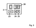
- each alphanumeric Character is designed as a seven-segment display.
- This display is essentially used to display the Sollund / Or Actual temperature used.
- the control unit also has the simplest design a menu key and two selection keys.
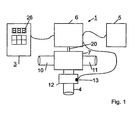
- the mixing water maker 1 consists essentially of a compact unit 2, completely plastered can be mounted.
- the device unit 2 is available with a Control unit 3 or a valve in data connection.
- the Unit 3 is usually in a functional context with a water outlet over the outlet 4 of the unit 2 is served.
- the device unit 2 is also with connected to an interface module 5.
- the interface module 5 may either be physically remote from the device unit 2 or integrated into the device unit 2. in this connection is the interface module 5 mounted in any case so that at the interface from the outside diagnostic and / or Programming devices can be connected.
- can an RS 485 interface can be mounted on plaster with the Device unit 2 is in data connection.
- the device unit 2 consists essentially of an electronic control unit 6 in addition to the actual electronic controller includes a stepper motor, via a transmission 20 with the actual mixer unit 7 and in the mixer unit 7 arranged control valve is connected.
- the Mixer unit 7 works purely mechanically and consists in essentially from a mixer body 8 of a warm and a cold water inlet 10 and 11 has.
- the supplied Hot and cold water is within the mixer body 8 in the predetermined by the electronic Reglereinhelt 6 Mixed ratio and thus the control unit 3 predetermined Target temperature ideally reached.
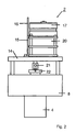
- FIG. 2 The exact structure of the compact unit 2 is shown in FIG. 2 shown in more detail.
- a base plate 14 bolted to an angle plate 15.
- the angle plate 15 also carries a holding plate 16 with a board, which essentially with the components for Structure of the electronic control unit 6 is equipped.
- the electronic control unit 6 acts as an actuator inserted stepper motor 17, via the transmission 20 acts on a rotatably mounted actuating body 21.
- the hot or cold water supply will be 10 or 11 more or less widely open and one of the respective position the adjusting body 21 corresponding water mixture within of the mixer body 8, which is above the outlet 4 flows.
- the actuator 21 is opposite the mixer body 8 sealed by a stuffing box nut 22.
- the device unit 2 explained above may be the same Functionality of course also in other geometric Arrangement to be constructed. It is only essential a control unit 6 acts on a stepping motor 17 and this via a gear 20, a control body 21st defined adjusted. In contrast to otherwise usual fabric elements or bimetallic solutions represents the respective Position of the transmission 20 a clearly defined and detectable size of the instantaneous actuator position and thus the adjusted hot-cold-water mixture.
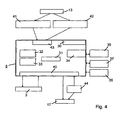
- the regulator unit arranged in the compact unit 2 6 is shown in more detail in Fig. 4.
- the regulator unit 6 includes in addition to a microcontroller 30 with an integrated Computer unit 31 and an integrated program memory 32 also has a data memory 33.
- the Regulator unit 6 with a serial interface 34 for Connection of the interface module 5 provided.
- the serial Interface 34 is assigned an interface driver 35.
- the controller unit 6 is also available with a reset controller 36 and an operating data memory 37 in Data Connection.
- the regulator unit 6 various digital inputs and outputs 40 for connecting the Operating unit 3 and the stepping motor 17. Of the Temperature sensor 13 is via different measuring amplifier 41 and 42 and one integrated in the microcontroller 30 Analog / digital converter 40 connected to the controller unit 6.
- the different measuring amplifiers 41 and 42 are necessary distinguishable by different control accuracies To realize temperature ranges. So can an outside the usual reference temperature lying temperature range be defined, the only with a coarse regulation is provided. This usually larger temperature range can with a measuring amplifier lower resolution be provided, since the measured values as such greater differences than in the temperature range associated with a finer control is provided.
- both the Program as well as the data memory are parameterized. This is the initial parameterization of the system based on a manufacturer in the program memory 32 of Microcontroller30 filed program. According to this Program will be the whole before the first start Runtime range, until by one of two corresponding limit switch 44 marked one end of achieved mechanical adjustment range of the actuating body 21 is. The position corresponding to this one endpoint becomes saved in the data memory 33. When approached The end point of the control area is usually the reference to trade from "only" cold water.
- each one is added to the Implementation of a temperature specification approached position of Actuator or the setpoint specification corresponding to this position in the form of a constantly changing and refining histogram stored in the data memory 33.
- the mixed water heater 1 thus provides a self-learning and self-adjusting system.
- a common temperature control is in a flow chart shown in FIG. 5.
- the controller 6 acts via the stepper motor 17 on the control valve.
- a first subordinate control loop is therefore in the regulation of Actual / target position of the stepping motor 17.
- On this Control circuit initially acts on the setpoint temperature specification of Control unit 3 a.
- This superimposed control loop for Temperature control receives an actual value feedback via the temperature sensor 13 as stated, depending on detected Temperature range over the first sense amplifier 41 or the second measuring amplifier 42 acts.
- Overtemperature detection or detection of a Water loss can be used.
- the controller is a constant target size given that the stepper motor 17 immediately in a Water-absorbing terminating position moves.
- the foregoing is a method and apparatus for electronic mixing water preparation described that by means of a compact unit 2 a mixed water treatment in connection with a previously unattained Ease of use allows. Due to an optimal Coordination between the electronic regulation and the mechanical actuators will have a high control speed at the same time extremely low sensory effort reached. In essence, the entire mixed water treatment solely by means of a single temperature sensor 13 done.
- the invention also relates to a method for Mixed water treatment, in which one via a control unit 3 definable predefinable setpoint via an electronic Control unit 6 as a function of a means a temperature sensor 13 detected actual value by means of a mechanical actuator 17 to a controlled system for Mixed water preparation acts.
- an over the control unit 3 predetermined target temperature of the reference water or that the reference water, whose target temperature can be specified via the control unit 3, exclusively by means of the temperature sensor 13 for actual value detection is mixed and in addition a gradient evaluation the temperature profile detected by the temperature sensor 13 for flow detection is made.
- the entire mixed water treatment by means of a temperature sensor 13 as the only sensor take place in that in addition to the mere actual value detection the temperature a gradient evaluation of the detected Temperature course is performed.
- the course of the Temperature gradient allows to determine if a Water flow takes place.
- the inventive method thus allows flow detection without a corresponding flow sensor.
- the Tracking of the actuator 17 is turned off, as soon as and as long as the gradient of the temperature profile is a predefinable Threshold falls below or below one predefinable threshold decreases. This means in concrete Embodiment that a temperature control only then takes place when actually a water flow occurs.
- Control accuracy can be distinguished.
- the range can be controlled with a control accuracy of be equipped with a tenth or a half degree. Outside the usual range of use is such Control accuracy not required. This area must can only be detected since the external environment, in particular the ambient temperature, detectable have to be. To get from this coarse control area in the Fine control range procedure, but not with Last accuracy to be worked. Also this distinction between a coarse and a fine control represents a measure to increase the life of the Appendix, since this also unnecessary actuator movements be avoided.
- This feature can be further developed by the tracking of the actuator 17 outside or also switched off outside of a defined temperature range or is prevented. This too is a measure to reduce unnecessary wear and energy consumption avoid.
- the gradient evaluation of the temperature profile for overtemperature detection and / or water failure detection is used in such a way that in the case of Recognition of the one and / or other event to the controller a control constant is specified such that the Actuator 17 in a water reference interrupting End position is moved.
- a control constant is specified such that the Actuator 17 in a water reference interrupting End position is moved.
- the method of the invention for Gradient evaluation of the temperature profile for a Overtemperature and / or cold water failure detection used.
- Overtemperature detection is important Safety feature in the household area to scald to prevent the user. It serves the same purpose to recognize in time, if necessary, the cold water supply is interrupted. A cold water failure leads otherwise at first too overheated Water outlet for safety reasons necessarily is avoid.
- the regulator unit 6 itself so self-parameterizing is designed so that in a first step Mininmal and / or maximum point of the control range, preferably the cold water supply, is approached and this Actuator setting corresponding setpoint specification in one Data memory 33 is stored and in further operation the corresponding to the respective temperature settings Actuator positions constantly in this data memory 33 in stored in a histogram and this constantly to be updated.
- the method is therefore the controller unit 6 self-parameterizing designed. At first startup will be at least approached a limit of the control range and in further operation based on successfully controlled temperatures a histogram of the respective temperature specifications corresponding actuator settings created.
- the system is therefore self-employed and above all self-learning, since the histograms are constantly being edited in the company and be updated and also with increasing operating time The system will be more accurate.
- controller unit 6 be connected to an operating data acquisition. This allows more comfort features such as an operating hours counter or the specification of water use times in the Hotel or restaurant area are realized.
Landscapes
- General Physics & Mathematics (AREA)
- Engineering & Computer Science (AREA)
- Automation & Control Theory (AREA)
- Physics & Mathematics (AREA)
- Control Of Temperature (AREA)
- External Artificial Organs (AREA)
- Accessories For Mixers (AREA)
- Pharmaceuticals Containing Other Organic And Inorganic Compounds (AREA)
- Control Of Non-Electrical Variables (AREA)
- Temperature-Responsive Valves (AREA)
- Domestic Plumbing Installations (AREA)
- Nozzles (AREA)
- Instantaneous Water Boilers, Portable Hot-Water Supply Apparatuses, And Control Of Portable Hot-Water Supply Apparatuses (AREA)
- Electrical Discharge Machining, Electrochemical Machining, And Combined Machining (AREA)
- Medicines Containing Plant Substances (AREA)
- Devices For Medical Bathing And Washing (AREA)
Priority Applications (3)
| Application Number | Priority Date | Filing Date | Title |
|---|---|---|---|
| DK02027886T DK1293855T3 (da) | 1999-12-18 | 2000-12-13 | Fremgangsmåde til tilberedning af blandingsvand |
| SI200030212T SI1240564T1 (en) | 1999-12-18 | 2000-12-13 | Electronic mixed water preparation device and method for preparing mixed water |
| EP02027886A EP1293855B1 (de) | 1999-12-18 | 2000-12-13 | Verfahren zur Mischwasserbereitung |
Applications Claiming Priority (3)
| Application Number | Priority Date | Filing Date | Title |
|---|---|---|---|
| DE19961183 | 1999-12-18 | ||
| DE19961183A DE19961183A1 (de) | 1999-12-18 | 1999-12-18 | Elektronischer Mischwasserbereiter und Verfahren zur Mischwasserbereitung |
| PCT/DE2000/004680 WO2001044884A2 (de) | 1999-12-18 | 2000-12-13 | Elektronischer mischwasserbereiter und verfahren zur mischwasserbereitung |
Related Child Applications (1)
| Application Number | Title | Priority Date | Filing Date |
|---|---|---|---|
| EP02027886A Division EP1293855B1 (de) | 1999-12-18 | 2000-12-13 | Verfahren zur Mischwasserbereitung |
Publications (2)
| Publication Number | Publication Date |
|---|---|
| EP1240564A2 EP1240564A2 (de) | 2002-09-18 |
| EP1240564B1 true EP1240564B1 (de) | 2003-09-03 |
Family
ID=7933224
Family Applications (2)
| Application Number | Title | Priority Date | Filing Date |
|---|---|---|---|
| EP00990591A Expired - Lifetime EP1240564B1 (de) | 1999-12-18 | 2000-12-13 | Elektronischer mischwasserbereiter und verfahren zur mischwasserbereitung |
| EP02027886A Expired - Lifetime EP1293855B1 (de) | 1999-12-18 | 2000-12-13 | Verfahren zur Mischwasserbereitung |
Family Applications After (1)
| Application Number | Title | Priority Date | Filing Date |
|---|---|---|---|
| EP02027886A Expired - Lifetime EP1293855B1 (de) | 1999-12-18 | 2000-12-13 | Verfahren zur Mischwasserbereitung |
Country Status (17)
| Country | Link |
|---|---|
| US (2) | US6688530B2 (enExample) |
| EP (2) | EP1240564B1 (enExample) |
| JP (1) | JP4819274B2 (enExample) |
| KR (1) | KR100743799B1 (enExample) |
| CN (1) | CN1259604C (enExample) |
| AT (2) | ATE274202T1 (enExample) |
| AU (1) | AU3002101A (enExample) |
| BG (1) | BG65392B1 (enExample) |
| DE (4) | DE19961183A1 (enExample) |
| DK (2) | DK1240564T3 (enExample) |
| ES (2) | ES2227382T3 (enExample) |
| IL (2) | IL150073A0 (enExample) |
| PL (1) | PL198219B1 (enExample) |
| PT (1) | PT1293855E (enExample) |
| SI (2) | SI1293855T1 (enExample) |
| TR (1) | TR200402244T4 (enExample) |
| WO (1) | WO2001044884A2 (enExample) |
Cited By (1)
| Publication number | Priority date | Publication date | Assignee | Title |
|---|---|---|---|---|
| WO2020164706A1 (de) | 2019-02-14 | 2020-08-20 | Oblamatik Ag | Funktionseinheit |
Families Citing this family (45)
| Publication number | Priority date | Publication date | Assignee | Title |
|---|---|---|---|---|
| DE10219171A1 (de) * | 2002-04-30 | 2003-11-13 | Kludi Gmbh & Co Kg | Einhebelarmatur |
| US6913203B2 (en) * | 2003-12-03 | 2005-07-05 | Delangis Eric | Self powered electronically controlled mixing valve |
| US20050125699A1 (en) * | 2003-12-05 | 2005-06-09 | Raymond Harper | Sarts password manager |
| US7690395B2 (en) | 2004-01-12 | 2010-04-06 | Masco Corporation Of Indiana | Multi-mode hands free automatic faucet |
| DE102004028062A1 (de) * | 2004-06-09 | 2006-01-12 | Hansa Metallwerke Ag | Sanitäres Thermostatventil |
| US8225961B2 (en) * | 2004-08-25 | 2012-07-24 | Bunn-O-Matic Corporation | Multiple hot water dispensing system |
| GB0500970D0 (en) * | 2005-01-18 | 2005-02-23 | Kohler Mira Ltd | Improvements in or relating to ablutionary Installations |
| US7458520B2 (en) | 2005-04-19 | 2008-12-02 | Masco Corporation Of Indiana | Electronic proportioning valve |
| US7475827B2 (en) | 2005-04-19 | 2009-01-13 | Masco Corporation Of Indiana | Fluid mixer |
| US7448553B2 (en) | 2005-04-19 | 2008-11-11 | Masco Corporation Of Indiana | Fluid mixer |
| US7584898B2 (en) | 2005-07-01 | 2009-09-08 | Masco Corporation Of Indiana | Manual override for electronic proportioning valve |
| US7867172B1 (en) | 2006-11-09 | 2011-01-11 | Dingane Baruti | Combination toothbrush and peak flow meter system |
| US8438672B2 (en) | 2005-11-11 | 2013-05-14 | Masco Corporation Of Indiana | Integrated electronic shower system |
| US20080000997A1 (en) * | 2006-03-03 | 2008-01-03 | Duane Smith | Safe-T-Shower |
| US9243756B2 (en) | 2006-04-20 | 2016-01-26 | Delta Faucet Company | Capacitive user interface for a faucet and method of forming |
| US8089473B2 (en) | 2006-04-20 | 2012-01-03 | Masco Corporation Of Indiana | Touch sensor |
| US8162236B2 (en) | 2006-04-20 | 2012-04-24 | Masco Corporation Of Indiana | Electronic user interface for electronic mixing of water for residential faucets |
| US8118240B2 (en) | 2006-04-20 | 2012-02-21 | Masco Corporation Of Indiana | Pull-out wand |
| US8365767B2 (en) | 2006-04-20 | 2013-02-05 | Masco Corporation Of Indiana | User interface for a faucet |
| US9243392B2 (en) | 2006-12-19 | 2016-01-26 | Delta Faucet Company | Resistive coupling for an automatic faucet |
| US8944105B2 (en) | 2007-01-31 | 2015-02-03 | Masco Corporation Of Indiana | Capacitive sensing apparatus and method for faucets |
| US7806141B2 (en) | 2007-01-31 | 2010-10-05 | Masco Corporation Of Indiana | Mixing valve including a molded waterway assembly |
| US8376313B2 (en) | 2007-03-28 | 2013-02-19 | Masco Corporation Of Indiana | Capacitive touch sensor |
| US7665483B1 (en) | 2007-10-25 | 2010-02-23 | Alberto Sid | Motorized shower diverter system |
| MX2010006473A (es) | 2007-12-11 | 2010-09-22 | Masco Corp | Disposicion de acoplamiento capacitivo para un grifo. |
| US7934662B1 (en) | 2008-02-15 | 2011-05-03 | Robert Jenkins | Thermostatic water mixing unit |
| US20100032488A1 (en) * | 2008-08-06 | 2010-02-11 | Garry Edward Yates | Mixing Valve Control System |
| US20110004994A1 (en) * | 2009-07-13 | 2011-01-13 | Luraco Technologies, Inc. | Apparatus, system and method for multi-function intelligent spa control |
| US8193659B2 (en) * | 2009-11-19 | 2012-06-05 | Ormat Technologies, Inc. | Power system |
| US8776817B2 (en) | 2010-04-20 | 2014-07-15 | Masco Corporation Of Indiana | Electronic faucet with a capacitive sensing system and a method therefor |
| US8561626B2 (en) | 2010-04-20 | 2013-10-22 | Masco Corporation Of Indiana | Capacitive sensing system and method for operating a faucet |
| CA2756952C (en) | 2010-11-04 | 2020-12-15 | Magarl, Llc | Electrohydraulic thermostatic control valve |
| CH704187B1 (de) | 2010-12-06 | 2021-11-15 | Eliane Zoccolillo Luethi | Sanitärsystem mit einer Mischzentrale. |
| DE202011000038U1 (de) * | 2011-01-07 | 2012-04-16 | Lindner Armaturen Gmbh | Elektronische Sanitärarmatur, insbesondere für Waschtische |
| EP3026183A1 (en) | 2012-03-07 | 2016-06-01 | Moen Incorporated | Electronic plumbing fixture fitting |
| US9175458B2 (en) | 2012-04-20 | 2015-11-03 | Delta Faucet Company | Faucet including a pullout wand with a capacitive sensing |
| NL2008698C2 (nl) | 2012-04-24 | 2013-10-28 | Henri Peteri Beheer Bv | Afgifteinrichting voor water. |
| US9574331B2 (en) * | 2012-06-18 | 2017-02-21 | Kenneth McLeod Wright | Shower flow monitor and display |
| CN103498949B (zh) * | 2013-09-11 | 2015-09-30 | 山东齿兴机械制造有限公司 | 冷热水混合恒温控制器 |
| FR3019914B1 (fr) * | 2014-04-14 | 2016-05-13 | Vernet | Procede de determination d'une loi de commande d'une vanne d'une cartouche thermostatique electronique, cartouche et mitigeur associes |
| CN103970163B (zh) * | 2014-05-14 | 2016-04-20 | 福州锐洁源电子科技有限公司 | 一种可调节温度供水系统及其使用方法 |
| CN104932295A (zh) * | 2015-04-29 | 2015-09-23 | 厦门建霖工业有限公司 | 一种多功能淋浴人性化控制方法 |
| CN105867456A (zh) * | 2016-04-01 | 2016-08-17 | 安庆市鸿裕工业产品设计有限公司 | 一种电子控温接口组件 |
| CN106037556B (zh) * | 2016-08-05 | 2018-05-25 | 无锡同春新能源科技有限公司 | 一种可以显示并调控汤水温度的智能泡脚桶 |
| DE102019203163A1 (de) * | 2019-03-08 | 2020-09-10 | Hansgrohe Se | Sanitäre Dusch-/Wascheinrichtung mit Dusch-/Waschprogrammbereitstellung |
Family Cites Families (26)
| Publication number | Priority date | Publication date | Assignee | Title |
|---|---|---|---|---|
| GB2056627B (en) * | 1979-08-14 | 1983-03-23 | Crosweller & Co Ltd W | Mixing valve |
| US4646964A (en) | 1982-03-26 | 1987-03-03 | Parker Electronics, Inc. | Temperature control system |
| DE8314239U1 (de) * | 1983-05-13 | 1983-09-15 | Getronik elektronische Geräte GmbH, 3002 Wedemark | Beruehrungsglos betaetigbare armatur |
| GB2143343A (en) * | 1983-07-13 | 1985-02-06 | Standard Telephones Cables Ltd | Thermostatically controlled mixer |
| NO152880C (no) * | 1983-08-30 | 1985-12-04 | Lyng Ind As | Temperaturpaavirkbar, elektronisk styrt blandeventil for blanding av to vaesker. |
| DE3518644A1 (de) * | 1985-05-23 | 1986-11-27 | Knebel & Röttger GmbH & Co, 5860 Iserlohn | Sanitaer-mischarmatur |
| US4696428A (en) * | 1986-07-10 | 1987-09-29 | Paul Shakalis | Electronic fluid temperature flow control system |
| DE3624799A1 (de) * | 1986-07-23 | 1988-01-28 | Ideal Standard | Elektronisch temperaturgeregelte mischarmatur |
| IL80806A0 (en) * | 1986-11-28 | 1987-02-27 | Avraham Kochal | Faucet mixing battery |
| US5361215A (en) * | 1987-05-27 | 1994-11-01 | Siege Industries, Inc. | Spa control system |
| DE3718039C2 (de) * | 1987-05-28 | 1994-04-21 | Ideal Standard | Elektronisch temperaturgeregelte Mischarmatur |
| GB8715717D0 (en) * | 1987-07-03 | 1987-08-12 | Armitage Shanks Ltd | Thermostatic valves |
| US4875623A (en) * | 1987-07-17 | 1989-10-24 | Memrysafe, Inc. | Valve control |
| DE3739676A1 (de) * | 1987-11-24 | 1989-06-08 | Eckerfeld Erika | Durchlauferhitzer mit elektronischer temperaturregelung |
| DE3838046A1 (de) * | 1988-11-09 | 1990-05-10 | Butzke Werke Aqua | Verfahren zum thermischen desinfizieren |
| US4941608A (en) * | 1988-12-23 | 1990-07-17 | Matsushita Electric Works, Ltd. | Hot water supplying system |
| US4923116A (en) * | 1989-05-24 | 1990-05-08 | Homan Gerald L | Bath water control system |
| DE4026110A1 (de) * | 1990-08-17 | 1992-02-20 | Grohe Armaturen Friedrich | Vorrichtung zur regelung und bedienung einer mischwasserbereitungsanlage |
| DE4401637C2 (de) * | 1993-01-22 | 2001-08-23 | Hansgrohe Ag | Sanitäre Mischarmatur |
| DE4430805A1 (de) * | 1993-09-01 | 1995-05-11 | Desch Kurt Michael | Elektronische Badewannen/Brause Armatur |
| DE4420334A1 (de) * | 1994-06-10 | 1995-12-14 | Grohe Armaturen Friedrich | Wasserarmaturensteuerung |
| JPH08123555A (ja) * | 1994-10-24 | 1996-05-17 | Matsushita Electric Ind Co Ltd | 湯水混合装置 |
| US5944255A (en) * | 1997-08-29 | 1999-08-31 | Shirmohamadi; Manuchehr | Shower water automatic temperature controller |
| US5979775A (en) * | 1998-01-23 | 1999-11-09 | Raya; Richard | Bathing water pre-mixing system |
| GB2335512A (en) * | 1998-03-16 | 1999-09-22 | Su Chao Ta | A water temperature detecting and controlling device |
| US6286764B1 (en) * | 1999-07-14 | 2001-09-11 | Edward C. Garvey | Fluid and gas supply system |
-
1999
- 1999-12-18 DE DE19961183A patent/DE19961183A1/de not_active Withdrawn
-
2000
- 2000-12-13 DK DK00990591T patent/DK1240564T3/da active
- 2000-12-13 PT PT02027886T patent/PT1293855E/pt unknown
- 2000-12-13 SI SI200030476T patent/SI1293855T1/xx unknown
- 2000-12-13 EP EP00990591A patent/EP1240564B1/de not_active Expired - Lifetime
- 2000-12-13 WO PCT/DE2000/004680 patent/WO2001044884A2/de not_active Ceased
- 2000-12-13 DE DE50007522T patent/DE50007522D1/de not_active Expired - Lifetime
- 2000-12-13 DE DE50003588T patent/DE50003588D1/de not_active Expired - Lifetime
- 2000-12-13 TR TR2004/02244T patent/TR200402244T4/xx unknown
- 2000-12-13 ES ES02027886T patent/ES2227382T3/es not_active Expired - Lifetime
- 2000-12-13 DK DK02027886T patent/DK1293855T3/da active
- 2000-12-13 AT AT02027886T patent/ATE274202T1/de not_active IP Right Cessation
- 2000-12-13 AU AU30021/01A patent/AU3002101A/en not_active Abandoned
- 2000-12-13 US US10/149,957 patent/US6688530B2/en not_active Expired - Lifetime
- 2000-12-13 JP JP2001545912A patent/JP4819274B2/ja not_active Expired - Fee Related
- 2000-12-13 PL PL355674A patent/PL198219B1/pl unknown
- 2000-12-13 KR KR1020027007792A patent/KR100743799B1/ko not_active Expired - Fee Related
- 2000-12-13 EP EP02027886A patent/EP1293855B1/de not_active Expired - Lifetime
- 2000-12-13 AT AT00990591T patent/ATE249067T1/de not_active IP Right Cessation
- 2000-12-13 ES ES00990591T patent/ES2206349T3/es not_active Expired - Lifetime
- 2000-12-13 CN CNB008173508A patent/CN1259604C/zh not_active Expired - Fee Related
- 2000-12-13 IL IL15007300A patent/IL150073A0/xx active IP Right Grant
- 2000-12-13 SI SI200030212T patent/SI1240564T1/xx unknown
- 2000-12-13 DE DE10083966T patent/DE10083966D2/de not_active Withdrawn - After Issue
-
2002
- 2002-06-06 BG BG106781A patent/BG65392B1/bg unknown
- 2002-06-06 IL IL150073A patent/IL150073A/en not_active IP Right Cessation
-
2004
- 2004-02-05 US US10/772,906 patent/US20040155116A1/en not_active Abandoned
Cited By (2)
| Publication number | Priority date | Publication date | Assignee | Title |
|---|---|---|---|---|
| WO2020164706A1 (de) | 2019-02-14 | 2020-08-20 | Oblamatik Ag | Funktionseinheit |
| US11796075B2 (en) | 2019-02-14 | 2023-10-24 | Oblamatik Ag | Functional unit |
Also Published As
Similar Documents
| Publication | Publication Date | Title |
|---|---|---|
| EP1240564B1 (de) | Elektronischer mischwasserbereiter und verfahren zur mischwasserbereitung | |
| DE60217198T2 (de) | Vorrichtung mit einem Wassermischventil | |
| DE60126855T2 (de) | Lehrsteuerpult für Roboter | |
| DE69122165T2 (de) | Regelgerät für Durchfluss und Temperatur von Fluiden | |
| DE68926370T2 (de) | Warmwasserversorgungsgerät | |
| DE3518645C2 (enExample) | ||
| EP1249544A1 (de) | Vorrichtung zur Steuerung der Wannenbefüllung einer Sanitärwanne | |
| EP2887170B1 (de) | Thermostat-Mischventil | |
| DE19622438A1 (de) | Vorrichtung und Verfahren zur Regelung des Durchflusses einer Flüssigkeit in einem geschlossenen Kreislauf | |
| EP2218840A1 (de) | Sanitärarmatur mit Joysticksteuerung | |
| DE4203613C2 (de) | Steuersystem für Raumheizanlagen | |
| DE3032390C2 (de) | Elektrischer Uhrenthermostat | |
| DE9100806U1 (de) | Regel- und Steuerungssystem für ein vorzugsweise gasbeheiztes Wassererhitzergerät | |
| DE4107860C2 (enExample) | ||
| EP1450061B1 (de) | Vorrichtung zur Regelung der Drehzahl des Abtriebdrehteils einer Viskositätskupplung | |
| DE19513394A1 (de) | Temperaturgeführte Leistungsansteuerung für elektrisch betriebene Pumpenaggregate | |
| DE4401637A1 (de) | Sanitäre Mischarmatur | |
| EP0876643A1 (de) | Wasserentnahmesystem | |
| DE69218322T2 (de) | Thermostat mit Sollwert-Erhöhung oder -Absenkung sowie einer einfachen optischen Zustandsanzeige. | |
| DE102008013946B3 (de) | Verfahren zum Steuern eines elektrischen Durchlauferhitzers | |
| DE69116888T2 (de) | Messumformer mit multifunktioneller einstellung | |
| EP4127332A1 (de) | Sanitärarmatur mit einem nicht-axialen thermostatmischer sowie verfahren zur montage einer sanitärarmatur | |
| DE4447893C2 (de) | Sanitäre Mischarmatur | |
| DE3042947A1 (de) | Schaltungsanordnung | |
| EP3889365A1 (de) | Verfahren zum betrieb einer thermostatmischarmatur sowie thermostatmischarmatur |
Legal Events
| Date | Code | Title | Description |
|---|---|---|---|
| PUAI | Public reference made under article 153(3) epc to a published international application that has entered the european phase |
Free format text: ORIGINAL CODE: 0009012 |
|
| 17P | Request for examination filed |
Effective date: 20020710 |
|
| AK | Designated contracting states |
Kind code of ref document: A2 Designated state(s): AT BE CH CY DE DK ES FI FR GB GR IE IT LI LU MC NL PT SE TR |
|
| AX | Request for extension of the european patent |
Free format text: AL;LT;LV;MK;RO;SI PAYMENT 20020710 |
|
| 17Q | First examination report despatched |
Effective date: 20021112 |
|
| GRAH | Despatch of communication of intention to grant a patent |
Free format text: ORIGINAL CODE: EPIDOS IGRA |
|
| GRAS | Grant fee paid |
Free format text: ORIGINAL CODE: EPIDOSNIGR3 |
|
| GRAA | (expected) grant |
Free format text: ORIGINAL CODE: 0009210 |
|
| RIN1 | Information on inventor provided before grant (corrected) |
Inventor name: WACK, VOLKER Inventor name: PETZOLD, HEIKO |
|
| AK | Designated contracting states |
Kind code of ref document: B1 Designated state(s): AT BE CH CY DE DK ES FI FR GB GR IE IT LI LU MC NL PT SE TR |
|
| AX | Request for extension of the european patent |
Extension state: SI |
|
| PG25 | Lapsed in a contracting state [announced via postgrant information from national office to epo] |
Ref country code: IE Free format text: LAPSE BECAUSE OF FAILURE TO SUBMIT A TRANSLATION OF THE DESCRIPTION OR TO PAY THE FEE WITHIN THE PRESCRIBED TIME-LIMIT Effective date: 20030903 |
|
| REG | Reference to a national code |
Ref country code: GB Ref legal event code: FG4D Free format text: NOT ENGLISH |
|
| REG | Reference to a national code |
Ref country code: CH Ref legal event code: EP |
|
| REF | Corresponds to: |
Ref document number: 50003588 Country of ref document: DE Date of ref document: 20031009 Kind code of ref document: P |
|
| REG | Reference to a national code |
Ref country code: IE Ref legal event code: FG4D Free format text: GERMAN |
|
| REG | Reference to a national code |
Ref country code: SE Ref legal event code: TRGR |
|
| GBT | Gb: translation of ep patent filed (gb section 77(6)(a)/1977) |
Effective date: 20031110 |
|
| PG25 | Lapsed in a contracting state [announced via postgrant information from national office to epo] |
Ref country code: GR Free format text: LAPSE BECAUSE OF FAILURE TO SUBMIT A TRANSLATION OF THE DESCRIPTION OR TO PAY THE FEE WITHIN THE PRESCRIBED TIME-LIMIT Effective date: 20031203 |
|
| PG25 | Lapsed in a contracting state [announced via postgrant information from national office to epo] |
Ref country code: CY Free format text: LAPSE BECAUSE OF FAILURE TO SUBMIT A TRANSLATION OF THE DESCRIPTION OR TO PAY THE FEE WITHIN THE PRESCRIBED TIME-LIMIT Effective date: 20031213 Ref country code: LU Free format text: LAPSE BECAUSE OF NON-PAYMENT OF DUE FEES Effective date: 20031213 |
|
| REG | Reference to a national code |
Ref country code: CH Ref legal event code: NV Representative=s name: TROESCH SCHEIDEGGER WERNER AG |
|
| REG | Reference to a national code |
Ref country code: DK Ref legal event code: T3 |
|
| PG25 | Lapsed in a contracting state [announced via postgrant information from national office to epo] |
Ref country code: MC Free format text: LAPSE BECAUSE OF NON-PAYMENT OF DUE FEES Effective date: 20031231 |
|
| PG25 | Lapsed in a contracting state [announced via postgrant information from national office to epo] |
Ref country code: PT Free format text: LAPSE BECAUSE OF FAILURE TO SUBMIT A TRANSLATION OF THE DESCRIPTION OR TO PAY THE FEE WITHIN THE PRESCRIBED TIME-LIMIT Effective date: 20040203 |
|
| LTIE | Lt: invalidation of european patent or patent extension |
Effective date: 20030903 |
|
| REG | Reference to a national code |
Ref country code: IE Ref legal event code: FD4D |
|
| REG | Reference to a national code |
Ref country code: ES Ref legal event code: FG2A Ref document number: 2206349 Country of ref document: ES Kind code of ref document: T3 |
|
| ET | Fr: translation filed | ||
| PLBE | No opposition filed within time limit |
Free format text: ORIGINAL CODE: 0009261 |
|
| STAA | Information on the status of an ep patent application or granted ep patent |
Free format text: STATUS: NO OPPOSITION FILED WITHIN TIME LIMIT |
|
| 26N | No opposition filed |
Effective date: 20040604 |
|
| REG | Reference to a national code |
Ref country code: SI Ref legal event code: IF |
|
| PGFP | Annual fee paid to national office [announced via postgrant information from national office to epo] |
Ref country code: TR Payment date: 20061212 Year of fee payment: 7 |
|
| PGFP | Annual fee paid to national office [announced via postgrant information from national office to epo] |
Ref country code: DK Payment date: 20071220 Year of fee payment: 8 Ref country code: NL Payment date: 20071231 Year of fee payment: 8 |
|
| PGFP | Annual fee paid to national office [announced via postgrant information from national office to epo] |
Ref country code: AT Payment date: 20071218 Year of fee payment: 8 |
|
| PGFP | Annual fee paid to national office [announced via postgrant information from national office to epo] |
Ref country code: BE Payment date: 20071231 Year of fee payment: 8 |
|
| PGFP | Annual fee paid to national office [announced via postgrant information from national office to epo] |
Ref country code: SE Payment date: 20081222 Year of fee payment: 9 |
|
| BERE | Be: lapsed |
Owner name: *INNOTECH ELECTRONIC G.M.B.H. Effective date: 20081231 |
|
| PGFP | Annual fee paid to national office [announced via postgrant information from national office to epo] |
Ref country code: CH Payment date: 20090224 Year of fee payment: 9 |
|
| REG | Reference to a national code |
Ref country code: DK Ref legal event code: EBP |
|
| PG25 | Lapsed in a contracting state [announced via postgrant information from national office to epo] |
Ref country code: AT Free format text: LAPSE BECAUSE OF NON-PAYMENT OF DUE FEES Effective date: 20081213 |
|
| NLV4 | Nl: lapsed or anulled due to non-payment of the annual fee |
Effective date: 20090701 |
|
| PG25 | Lapsed in a contracting state [announced via postgrant information from national office to epo] |
Ref country code: BE Free format text: LAPSE BECAUSE OF NON-PAYMENT OF DUE FEES Effective date: 20081231 Ref country code: TR Free format text: LAPSE BECAUSE OF FAILURE TO SUBMIT A TRANSLATION OF THE DESCRIPTION OR TO PAY THE FEE WITHIN THE PRESCRIBED TIME-LIMIT Effective date: 20030903 |
|
| REG | Reference to a national code |
Ref country code: SI Ref legal event code: KO00 Effective date: 20090803 |
|
| PG25 | Lapsed in a contracting state [announced via postgrant information from national office to epo] |
Ref country code: NL Free format text: LAPSE BECAUSE OF NON-PAYMENT OF DUE FEES Effective date: 20090701 |
|
| PG25 | Lapsed in a contracting state [announced via postgrant information from national office to epo] |
Ref country code: DK Free format text: LAPSE BECAUSE OF NON-PAYMENT OF DUE FEES Effective date: 20090105 |
|
| EUG | Se: european patent has lapsed | ||
| REG | Reference to a national code |
Ref country code: CH Ref legal event code: PL |
|
| PG25 | Lapsed in a contracting state [announced via postgrant information from national office to epo] |
Ref country code: CH Free format text: LAPSE BECAUSE OF NON-PAYMENT OF DUE FEES Effective date: 20091231 Ref country code: LI Free format text: LAPSE BECAUSE OF NON-PAYMENT OF DUE FEES Effective date: 20091231 |
|
| PG25 | Lapsed in a contracting state [announced via postgrant information from national office to epo] |
Ref country code: SE Free format text: LAPSE BECAUSE OF NON-PAYMENT OF DUE FEES Effective date: 20091214 |
|
| PGFP | Annual fee paid to national office [announced via postgrant information from national office to epo] |
Ref country code: GB Payment date: 20110128 Year of fee payment: 11 |
|
| PGFP | Annual fee paid to national office [announced via postgrant information from national office to epo] |
Ref country code: FI Payment date: 20111219 Year of fee payment: 12 Ref country code: FR Payment date: 20120103 Year of fee payment: 12 Ref country code: ES Payment date: 20111219 Year of fee payment: 12 |
|
| PGFP | Annual fee paid to national office [announced via postgrant information from national office to epo] |
Ref country code: IT Payment date: 20111228 Year of fee payment: 12 |
|
| GBPC | Gb: european patent ceased through non-payment of renewal fee |
Effective date: 20121213 |
|
| PG25 | Lapsed in a contracting state [announced via postgrant information from national office to epo] |
Ref country code: FI Free format text: LAPSE BECAUSE OF NON-PAYMENT OF DUE FEES Effective date: 20121213 |
|
| REG | Reference to a national code |
Ref country code: FR Ref legal event code: ST Effective date: 20130830 |
|
| PG25 | Lapsed in a contracting state [announced via postgrant information from national office to epo] |
Ref country code: GB Free format text: LAPSE BECAUSE OF NON-PAYMENT OF DUE FEES Effective date: 20121213 Ref country code: FR Free format text: LAPSE BECAUSE OF NON-PAYMENT OF DUE FEES Effective date: 20130102 |
|
| PG25 | Lapsed in a contracting state [announced via postgrant information from national office to epo] |
Ref country code: IT Free format text: LAPSE BECAUSE OF NON-PAYMENT OF DUE FEES Effective date: 20121213 |
|
| REG | Reference to a national code |
Ref country code: ES Ref legal event code: FD2A Effective date: 20140306 |
|
| PG25 | Lapsed in a contracting state [announced via postgrant information from national office to epo] |
Ref country code: ES Free format text: LAPSE BECAUSE OF NON-PAYMENT OF DUE FEES Effective date: 20121214 |
|
| PGFP | Annual fee paid to national office [announced via postgrant information from national office to epo] |
Ref country code: DE Payment date: 20141231 Year of fee payment: 15 |
|
| REG | Reference to a national code |
Ref country code: DE Ref legal event code: R119 Ref document number: 50003588 Country of ref document: DE |
|
| PG25 | Lapsed in a contracting state [announced via postgrant information from national office to epo] |
Ref country code: DE Free format text: LAPSE BECAUSE OF NON-PAYMENT OF DUE FEES Effective date: 20160701 |