EP1239802B1 - Methods and apparatus for applying an elastic material in a curvilinear pattern on a continuously moving substrate - Google Patents
Methods and apparatus for applying an elastic material in a curvilinear pattern on a continuously moving substrate Download PDFInfo
- Publication number
- EP1239802B1 EP1239802B1 EP00984495A EP00984495A EP1239802B1 EP 1239802 B1 EP1239802 B1 EP 1239802B1 EP 00984495 A EP00984495 A EP 00984495A EP 00984495 A EP00984495 A EP 00984495A EP 1239802 B1 EP1239802 B1 EP 1239802B1
- Authority
- EP
- European Patent Office
- Prior art keywords
- roll
- elastic material
- substrate
- recited
- oscillation unit
- Prior art date
- Legal status (The legal status is an assumption and is not a legal conclusion. Google has not performed a legal analysis and makes no representation as to the accuracy of the status listed.)
- Expired - Lifetime
Links
- 239000013013 elastic material Substances 0.000 title claims description 169
- 239000000758 substrate Substances 0.000 title claims description 150
- 238000000034 method Methods 0.000 title claims description 36
- 230000010355 oscillation Effects 0.000 claims description 59
- 238000012546 transfer Methods 0.000 claims description 56
- 238000005096 rolling process Methods 0.000 claims description 52
- 239000000853 adhesive Substances 0.000 claims description 18
- 230000001070 adhesive effect Effects 0.000 claims description 18
- 239000000463 material Substances 0.000 claims description 8
- 238000011144 upstream manufacturing Methods 0.000 claims 4
- 230000002745 absorbent Effects 0.000 description 6
- 239000002250 absorbent Substances 0.000 description 6
- 239000002131 composite material Substances 0.000 description 6
- 238000006073 displacement reaction Methods 0.000 description 6
- 238000004519 manufacturing process Methods 0.000 description 3
- 238000012986 modification Methods 0.000 description 3
- 230000004048 modification Effects 0.000 description 3
- 230000004075 alteration Effects 0.000 description 2
- 230000008901 benefit Effects 0.000 description 2
- 238000012545 processing Methods 0.000 description 2
- 244000043261 Hevea brasiliensis Species 0.000 description 1
- 239000004820 Pressure-sensitive adhesive Substances 0.000 description 1
- 238000000576 coating method Methods 0.000 description 1
- 238000010276 construction Methods 0.000 description 1
- 238000007796 conventional method Methods 0.000 description 1
- 238000005520 cutting process Methods 0.000 description 1
- 230000001419 dependent effect Effects 0.000 description 1
- 230000006870 function Effects 0.000 description 1
- 238000009434 installation Methods 0.000 description 1
- 238000005259 measurement Methods 0.000 description 1
- 230000007246 mechanism Effects 0.000 description 1
- 229920003052 natural elastomer Polymers 0.000 description 1
- 229920001194 natural rubber Polymers 0.000 description 1
- 230000008707 rearrangement Effects 0.000 description 1
- 238000004381 surface treatment Methods 0.000 description 1
- 229920003051 synthetic elastomer Polymers 0.000 description 1
- 230000001052 transient effect Effects 0.000 description 1
Images


Classifications
-
- A—HUMAN NECESSITIES
- A61—MEDICAL OR VETERINARY SCIENCE; HYGIENE
- A61F—FILTERS IMPLANTABLE INTO BLOOD VESSELS; PROSTHESES; DEVICES PROVIDING PATENCY TO, OR PREVENTING COLLAPSING OF, TUBULAR STRUCTURES OF THE BODY, e.g. STENTS; ORTHOPAEDIC, NURSING OR CONTRACEPTIVE DEVICES; FOMENTATION; TREATMENT OR PROTECTION OF EYES OR EARS; BANDAGES, DRESSINGS OR ABSORBENT PADS; FIRST-AID KITS
- A61F13/00—Bandages or dressings; Absorbent pads
- A61F13/15—Absorbent pads, e.g. sanitary towels, swabs or tampons for external or internal application to the body; Supporting or fastening means therefor; Tampon applicators
- A61F13/15577—Apparatus or processes for manufacturing
- A61F13/15585—Apparatus or processes for manufacturing of babies' napkins, e.g. diapers
- A61F13/15593—Apparatus or processes for manufacturing of babies' napkins, e.g. diapers having elastic ribbons fixed thereto; Devices for applying the ribbons
- A61F13/15609—Apparatus or processes for manufacturing of babies' napkins, e.g. diapers having elastic ribbons fixed thereto; Devices for applying the ribbons the ribbons being applied in an irregular path
Definitions
- the present invention relates to a composite web structure and methods and apparatus for applying an elastic material, particularly wide band elastic materials, in a curvilinear pattern on a continuously moving substrate. More particularly, the present invention relates to methods and apparatus for applying wide band elastic materials in curvilinear patterns on continuously moving substrates with severe enough angular displacement to produce a composite web structure, such as a disposable diaper or other absorbent article, with regions having the attached wide band elastic materials, such as leg cuff/containment flap regions, which are more "anatomically correct”. Even more particularly the present invention relates to novel methods and apparatus for applying wide band elastic materials in curvilinear patterns on continuously moving substrates having minimal linear transverse direction motion, in relation to the substrate path.
- curvilinear placement is desired to be "anatomically correct", generally in the leg opening region of an absorbent article.
- curvilinear placement is perceived as having a better fit on a body of a wearer of the absorbent article.
- Curving the wide band elastic attachment material has been very difficult to accomplish and practice at high speed. Manufacturers have to settle for compromises, such as making disposable diapers having straight bands of elastic or reducing line speed.
- U.S. Pat. No. 2.592.581 to Lorig discloses a method and apparatus for positioning a strip utilizing a roll which may be cylindrical, concave, or convex as desired to suit various installations.
- U.S. Pat. No. 4.081.301 to Buell adhesive is intermittently applied to the elastic material while the elastic and web substrate are continuously run at high speed.
- U.S. Pat. No. 3.828.367. discloses that a pair of elastic ribbons are fed to curved grooves in a roll under which a continuous web passes.
- a rotatable nip roll uses a rotatable nip roll to press an elastic member against the web so the elastic member is spaced a predetermined maximum distance from a dwell line, a rotatable buffer roll above and in rolling engagement with the rotatable nip roll to cushion the rotatable nip roll against transient perturbations, and an oscillating roll, oscillating in a path transverse to a direction of web travel, above and spaced apart a predetermined length from the rotatable buffer roll.
- the oscillating roll applies the elastic member in a curved line on the rotatable buffer roll, with the predetermined maximum distance of the elastic member from the dwell line being directly proportional to the predetermined length between the oscillating roll and the rotatable buffer roll.
- the method and apparatus of the present invention allows for high speed forming of continuously moving substrates having, as attached elements, elastic materials, such as wide band elastic materials, placed with severe angular displacement in a curvilinear pattern on a continuously moving substrate by allowing a roller to roll and pivot while placing the elastic materials either on a transfer roll or directly on a substrate.
- the present invention unlike the prior art, while rolling also oscillates in a plane generally transverse to the substrate path, thus providing a curvilinear pattern with no required linear movement of the roller across the substrate transverse direction.
- the present invention relates to apparatus and methods for applying at least one elastic material, in a curvilinear path, onto a continuously moving substrate.
- the apparatus for applying at least one web of elastic material in a curvilinear path onto a continuously moving substrate has a transporting apparatus for continuously moving the substrate along a substrate path, a rotatable transfer roll, having a transfer roll axis adapted to be in rolling engagement with the substrate and to press the elastic material against the substrate along the curvilinear path, an oscillation unit having at least a first roll having a first roll axis, the first roll being mounted for rolling engagement with a surface of the transfer roll, the first roll also mounted for pivoting about a pivot axis parallel to the substrate path with the pivot axis plane further from the point of rolling engagement than the first roll axis such that the first roll is operative to pivot in a plane generally traverse to the substrate path while rolling thus being effective to apply the elastic material to said transfer roll along the curvilinear path, an elastic material supply for providing the elastic material to the first roll of said oscillation unit, an oscillating drive connected to said oscillation unit for oscillating said oscillation unit in a plane generally transverse to the
- the method applies at least one web of elastic material in a curvilinear path onto a continuously moving substrate by moving the substrate along the substrate path, supplying the elastic material to at least a first roll having a first roll axis, the first roll being mounted for rolling engagement with a surface of said transfer roll, and for pivoting about a pivot axis parallel to the substrate path with the pivot axis plane further from the point of rolling engagement than the first roll axis such that the first roll is operative to pivot in a plane generally traverse to the substrate path while rolling thus being effective to apply the elastic material to said transfer roll along the curvilinear path, oscillating the oscillation unit in a path generally transverse to the substrate path applying the elastic material from the first roll to the transfer roll in a curvilinear path configuration, applying the elastic material, in the curvilinear path configuration, from the transfer roll to the substrate and bonding the elastic material, in the curvilinear path configuration, to the substrate.
- the transfer roll may be deleted and the first roll may directly contact the substrate to apply the elastic material
- FIG. 1 shows an apparatus for applying a pair of elastic materials 4 and 5 to a substrate 7 along a curvilinear path. While a pair of elastic materials is shown, the apparatus may also be used to apply only one elastic material. For the purposes of discussion, only one of the elastic materials and its related apparatus will be discussed herein since the elastic materials and the apparatus for applying each of the elastic materials to the web are substantially identical.
- the elastic material 4 is relatively flat, includes wide surface 6. and has a width considerably greater than its thickness.
- the elastic material 4 comes from an elastic material supply 3 and may be supplied in any known manner that permits a continuous high speed operation. This includes pulling elastic materials, in a tangle free manner, from a box, supplying elastic materials from a reel on which the elastic materials have been wound, receiving the elastic materials directly from another processing unit which forms the elastic material or any other supply manner known in the art. Since, for the purposes of this invention, the exact manner of elastic material supply is not important, the manner of supply has not been shown.
- the elastic material 4 may be either in the form of a natural rubber, a synthetic elastomer or a combination of materials, such as those shown in U.S. Pat. No.
- the elastic material is a combined leg cuff and containment flap such as that detailed in U.S. Pat. No. 5.827.387 issued October 27. 1998. to Reynolds et al.
- the apparatus 10 for applying elastic materials (4 and 5) to a substrate 7. includes a transporting apparatus 20, which may be any conventionally known type of transporting apparatus, and in FIG.1 includes two rolls (22 and 24) for continuously moving the substrate along a substrate path as shown by the direction of substrate transport arrow 25.
- Attachment pieces (8 and 9) may be present on the substrate and the substrate may have other additional elements, which are not shown and will not be further discussed, depending on the exact nature of the method for preparing the article.
- At least one elastic material is supplied in any known manner by an elastic material supply 3, including, as shown in FIG. 1, supplying the elastic material using a guide 32.
- the guide may be a roll or a bar or any other mechanism that can guide the elastic material to a first roll, also called a roller, of an oscillation unit.
- the elastic material is any band or ribbon type elastic material, however it is preferably a wide band elastic material having a width of about 12.7-101.6 mm (one half to about four inches), preferably a width of about 25.4 - 101.6 mm (one to about four inches) and most preferably about 50.8 - 101.6 mm (two to about four inches).
- Bonding apparatus 34 supplies adhesive at some point prior to the application of the elastic materials to the substrate.
- the exact positioning of the adhesive application is not critical, as long as the bonding apparatus applies the adhesive prior to the application of the elastic materials to the substrate.
- the application of the adhesive should be prior to the oscillation of the elastic material to reduce the complexity of the bonding apparatus, since application of the adhesive during or after oscillation of the elastic material would also require oscillation of the bonding apparatus.
- Adhesives may be of any known conventional type, so long as the adhesive causes minimal or no interference with the high speed application of the elastic materials to the substrate.
- One example is a pressure-sensitive adhesive.
- the bonding apparatus may be an ultrasonic unit properly positioned to be able to properly secure the elastic material to the substrate, such as, for example, at the position of a nip roll 60 in Fig. 1.
- the ultrasonic unit and a transfer roll or a first roll may provide a nip allowing ultrasonic energy to properly secure the elastic material to the substrate.
- An ultrasonic unit may be a suitable generator to power an ultrasonic horn and a suitable ultrasonic horn such as a rotary ultrasonic horn taught in U.S. Pat. No. 5.110.403 to Ehlert.
- the ultrasonic horn may be a stationary ultrasonic horn as are well known to those skilled in the art.
- the elastic material continues on to the oscillation unit 40 where it engages a first roll 42.
- a roller or caster which is a part of the oscillation unit and allows for rolling engagement of the elastic material as the elastic material is fed to the roller.
- the first roll also has a pivot axis which allows pivoting while the first roll is in rolling engagement with either a transfer roll 50 or the substrate 7.
- the roller is able to roll in addition to being pivoted, by oscillation in a plane transverse to the direction of movement of the substrate.
- This allows an elastic material, preferably a wide band elastic material, to be curved with severe enough angular displacement, up to about sixty degrees, to be perceived as more "anatomically correct" in a final article incorporating the substrate and elastic material .
- a wide band elastic material about 25.4 mm (one inch) in width, may be applied in a sinusoidal stretched manner so that the greatest overall distance from a top edge of the wide band elastic material at the top of a sine wave to a bottom (opposing) edge of the same wide band elastic material at the bottom of the sine wave is about 89 mm (three and one-half inches) or an angle of about sixty-four degrees (based on a right triangle).
- Fig. 2 shows the direction of travel 46 of the elastic material 4 in relation to the roller 42 and onto a transfer roll 50.
- the exact direction of travel is not critical as long as the roller is able to apply the elastic material either to the transfer roll in a curvilinear manner for application to the substrate or directly to the substrate in a curvilinear manner.
- the roller must be constructed to that the roller can be pivoted in a direction perpendicular to a rolling direction so as to apply the elastic material in a curvilinear pattern.
- These are generally known as rollers with a crown or crowned rollers. It is also required that the roller be able to be oscillated in a plane traverse to the substrate path while the roller is rolling on the transfer roll or the substrate.
- a roller having a pivot axis and a crowned surface.
- the pivot axis allows the roller to be oscillated, that is to say pivoted, through part or all of the roller's crown surface while the roller is rolling.
- the pivot axis may be above, below or tangent to a highest point on the crowned roller surface which furthest away from the point of elastic application to the transfer roll or substrate and the pivot axis must also be parallel to the substrate path when contacting the transfer roll or substrate to allow roller rolling motion while still being able to pivot in a direction perpendicular to the substrate path.
- the pivot axis is perpendicular to a centerline of the rolling axis.
- the roller By being able to pivot in a direction transverse to the substrate path while rolling, the roller is thus able to "travel" through part or all of the crowned roller surface in a direction transverse to the substrate path and thus apply elastic material in a curvilinear pattern to the transfer roll or substrate.
- the crown has a radius of curvature which matches a pivot radius. The pivot radius is determined by extending the pivot axis through the centerline of a rolling axis of the roller and measuring the radius from the thus extended pivot axis/centerline intersection to the point of application of the elastic material to the transfer roll or substrate.
- the crown has a radius which is equal to a maximum diameter of the crowned roller.
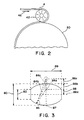
- the roller is similar to a football or a football having its pointed ends removed to provide parallel and planer opposing sides while still providing the crowned roller surface suitable for rolling.
- Figure 3 shows one embodiment of such a roller having a center diameter 80 of 101.6 mm (4.0000 inches) and an end diameter 82 of 33 mm (1.3166 inches) at both ends.
- Figure 3 also shows the position of three pivot axises 84a. 84b and 84c in relation to the centerline 87 and the rolling or first axis 86a. 86b and 86c.
- the pivot axis lies on the centerline and has an offset 88 25.4 mm (1.0000 inch) above the rolling or first axis of the first roll or roller.
- the overall length 89 of the roller is 12.7 mm (5.0000 inches) and the curved rolling surfaces have a radius 85 of 76.2 mm (3.0000 inches) with the two centerpoints for the diameter on the vertical centerline, 25.4 mm (1.0000 inch) above and below the rolling or first axis.
- this embodiment has a common centerpoint for both the pivot axis and the roller surface radius.
- the overall length of the roller will vary upon the specific application or use of the roller and will be dependent upon at least the width of the elastic material.
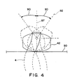
- Figure 4 shows a range of oscillation 90 of the roller of Figure 2 as it is oscillated in the plane transverse to the substrate path.
- the range of oscillation is about 40 degrees to the left or the right with the angle of the oscillation being formed with respect to the vertical centerline 87 of the roller and a line 92 perpendicular to the pivot axis and parallel to the rolling or first axis.
- This range of oscillation 90 allows the elastic material 4 to be placed on the transfer roll 50 in a curvilinear manner.
- this roller with the offset pivot axis provides sufficient transverse, or cross-direction, motion, relative to the substrate path while also causing minimal disturbance and twisting to the incoming elastic material path prior to application of the elastic material to the transfer roll or substrate.
- Fig. 5 shows a side view of the oscillation unit with the roller in rolling engagement with the transfer roll.
- the oscillating drive arm which forms the pivot axis, has an offset 88 25.4 mm (1.0000 inch) above the rolling or first axis of the roller.
- Fig. 6 is a top view of the oscillation unit with the roller.
- the roller may be held at one end, as is shown in Figure 6. or both ends of the rolling or first axis, but the roller, no matter how it is held for rolling motion, must be able to pivot as described previously.
- the oscillating drive oscillates as shown by the oscillating drive arrow 73.
- the roller may be constructed in any manner so the elastic material remains on the roller and does not bunch up or snag upon application.
- the specific roller and transport roll surface treatments will vary depending on the specific application or use, the location of the roller pivot axis and substrate characteristics.
- the roller and transport roll may have any conventionally known treated surface which facilitates the application of the elastic material to the substrate.
- the apparatus and method rely on the ability of the elastic material to track the highest surface speed of the roller so that transverse, or cross-machine, displacement is achieved while oscillating the roller.
- An oscillating drive 70 oscillates the oscillation unit in a plane generally transverse to the substrate path through an oscillating drive arm 72. as shown in Figs. 5 and 6.
- the oscillating drive may be of a type well-known in the art and consequently will not be further described herein.
- Oscillating drive arm 72 is fixed to oscillating drive 70.
- Roller 42 must have a roller arm 43 mounted for pivotation to oscillating drive arm 72 so that the roller arm is capable of oscillating in a plane transverse to the direction of movement of the substrate while rolling.
- Fig. 6 shows a top view of the oscillation unit.
- Arrow 73 is the direction of oscillation or pivotation.
- the oscillating drive arm and roller arm may be a single connecting arm or multiple connecting arms cooperating so as to oscillate the roller in the manner described herein while the first roll is in rolling engagement with either the transfer roll or the substrate.
- the oscillating drive arm may also be directly connected to the roller.
- the roller may be held at either or both ends of an axis which allows rolling, but the roller, no matter how it is held for rolling motion, must be able to pivot as described previously.
- the guide may also be part of the oscillation unit. It is a requirement that the roll that is actually in engagement with either the transfer roll or the substrate be in both rolling and pivoting engagement, as previously described with the transfer roll or substrate.
- the roller with the engaged elastic material, is in rolling and pivoting engagement with either the transfer roll 50 in one embodiment or directly with the substrate 7 in a second embodiment.
- the elastic material is then transferred from the roller to either the transfer roll in a curvilinear configuration and then applied to the substrate ( Figure 1) or directly to the substrate in a curvilinear configuration.
- transfer roll with the engaged curvilinear elastic material, is in rolling engagement with the substrate, and rotates to apply the elastic material to the substrate in the desired curvilinear pattern.
- transfer roll/nip roll configuration may include or be replaced by the bonding apparatus in the form of an ultrasonic unit able to properly secure the elastic material at the location where the elastic material is applied to the substrate.
- it is possible to use multiple transfer rolls in the present invention it is less complex and therefore preferable to utilize only a single transfer roll, even when utilizing multiple rollers as is shown in FIG. 1.
- the transfer roll may also be a variable velocity roll, with or without a hot knife, or other type of cutting roll such that the elastic material is curved, held, cut and applied in discrete units in the desired curvilinear manner.
- Other conventional measures such as vacuum and/or roll surface coatings, may be used in conjunction with the transfer roll to keep the elastic material engaged on the transfer roll.
- the substrate with the attached curvilinear elastic material continues on the substrate path for further processing.
- the elastic material may be leg elastic, but preferably the elastic materials define the previously described leg cuff/containment flap elastic materials.
- the overall apparatus is not complex.
- this apparatus and method allows high speed placement of wide band elastic materials onto a substrate, while third, allowing more severe angular displacement of the elastic material, with respect to the substrate path 25. in the composite web structure to achieve a better fit of the final article about the body of the wearer.
- the substrate and elastic material composite may be stored for later use in any known manner or alternatively, the composite may be used immediately in the fabrication of disposable garments such as disposable diapers.
- the curved elastic in each individual diaper fabricated from the substrate and elastic material composite provides elastic materials which are contoured to fit the shape of the body on which the diaper is worn and thereby provide a better fit or seal of the diaper against the body.
- the benefit of the method and apparatus of this invention may be obtained while manufacturing elasticized disposable diapers or other disposable garments at very high production speeds and having severe elastic material angular placement.
Landscapes
- Health & Medical Sciences (AREA)
- Engineering & Computer Science (AREA)
- Vascular Medicine (AREA)
- Epidemiology (AREA)
- Biomedical Technology (AREA)
- Heart & Thoracic Surgery (AREA)
- Manufacturing & Machinery (AREA)
- Life Sciences & Earth Sciences (AREA)
- Animal Behavior & Ethology (AREA)
- General Health & Medical Sciences (AREA)
- Public Health (AREA)
- Veterinary Medicine (AREA)
- Absorbent Articles And Supports Therefor (AREA)
- Treatment Of Fiber Materials (AREA)
Applications Claiming Priority (3)
| Application Number | Priority Date | Filing Date | Title |
|---|---|---|---|
| US471687 | 1999-12-23 | ||
| US09/471,687 US6287409B1 (en) | 1999-12-23 | 1999-12-23 | Methods and apparatus for applying an elastic material in a curvilinear pattern on a continuously moving substrate |
| PCT/US2000/034472 WO2001045611A1 (en) | 1999-12-23 | 2000-12-19 | Methods and apparatus for applying an elastic material in a curvilinear pattern on a continuously moving substrate |
Publications (2)
| Publication Number | Publication Date |
|---|---|
| EP1239802A1 EP1239802A1 (en) | 2002-09-18 |
| EP1239802B1 true EP1239802B1 (en) | 2007-05-09 |
Family
ID=23872631
Family Applications (1)
| Application Number | Title | Priority Date | Filing Date |
|---|---|---|---|
| EP00984495A Expired - Lifetime EP1239802B1 (en) | 1999-12-23 | 2000-12-19 | Methods and apparatus for applying an elastic material in a curvilinear pattern on a continuously moving substrate |
Country Status (8)
| Country | Link |
|---|---|
| US (1) | US6287409B1 (enExample) |
| EP (1) | EP1239802B1 (enExample) |
| JP (1) | JP2003517880A (enExample) |
| AU (1) | AU2110401A (enExample) |
| DE (1) | DE60034809T2 (enExample) |
| MX (1) | MXPA02006104A (enExample) |
| NO (1) | NO322568B1 (enExample) |
| WO (1) | WO2001045611A1 (enExample) |
Families Citing this family (74)
| Publication number | Priority date | Publication date | Assignee | Title |
|---|---|---|---|---|
| US6589149B1 (en) * | 2000-08-15 | 2003-07-08 | Kimberly-Clark Worldwide, Inc. | Method and apparatus for applying a curved component to a moving web |
| US6440246B1 (en) * | 2000-08-15 | 2002-08-27 | Kimberly-Clark Worldwide, Inc. | Method of applying curved leg elastics using rotating disks |
| US6375769B1 (en) * | 2000-08-15 | 2002-04-23 | Kimberly-Clark Worldwide, Inc. | Method of applying curved leg elastics using pucks with curved surfaces |
| US20040167493A1 (en) * | 2003-02-21 | 2004-08-26 | Sca Hygiene Products Ab | Arrangement and method for applying elastic element to a material web |
| US7172669B2 (en) * | 2003-03-07 | 2007-02-06 | Sca Hygiene Products Ab | Method for applying elastic members on a pant-shaped absorbent article |
| US8417374B2 (en) | 2004-04-19 | 2013-04-09 | Curt G. Joa, Inc. | Method and apparatus for changing speed or direction of an article |
| US7638014B2 (en) | 2004-05-21 | 2009-12-29 | Curt G. Joa, Inc. | Method of producing a pants-type diaper |
| FR2882535B1 (fr) * | 2005-02-28 | 2007-04-13 | Michelin Soc Tech | Dispositif et procede de fabrication de nappes ondulees |
| JP4397847B2 (ja) * | 2005-03-31 | 2010-01-13 | 大王製紙株式会社 | 吸収性物品における弾性部材の取付装置 |
| US7975584B2 (en) | 2007-02-21 | 2011-07-12 | Curt G. Joa, Inc. | Single transfer insert placement method and apparatus |
| US9433538B2 (en) | 2006-05-18 | 2016-09-06 | Curt G. Joa, Inc. | Methods and apparatus for application of nested zero waste ear to traveling web and formation of articles using a dual cut slip unit |
| US10456302B2 (en) | 2006-05-18 | 2019-10-29 | Curt G. Joa, Inc. | Methods and apparatus for application of nested zero waste ear to traveling web |
| US7780052B2 (en) * | 2006-05-18 | 2010-08-24 | Curt G. Joa, Inc. | Trim removal system |
| US9622918B2 (en) * | 2006-05-18 | 2017-04-18 | Curt G. Joe, Inc. | Methods and apparatus for application of nested zero waste ear to traveling web |
| US7731815B2 (en) * | 2006-11-06 | 2010-06-08 | The Procter & Gamble Company | Method and apparatus for nonlinear laying of material |
| US9550306B2 (en) | 2007-02-21 | 2017-01-24 | Curt G. Joa, Inc. | Single transfer insert placement and apparatus with cross-direction insert placement control |
| US9944487B2 (en) | 2007-02-21 | 2018-04-17 | Curt G. Joa, Inc. | Single transfer insert placement method and apparatus |
| US9387131B2 (en) | 2007-07-20 | 2016-07-12 | Curt G. Joa, Inc. | Apparatus and method for minimizing waste and improving quality and production in web processing operations by automated threading and re-threading of web materials |
| US8398793B2 (en) | 2007-07-20 | 2013-03-19 | Curt G. Joa, Inc. | Apparatus and method for minimizing waste and improving quality and production in web processing operations |
| US8182624B2 (en) * | 2008-03-12 | 2012-05-22 | Curt G. Joa, Inc. | Registered stretch laminate and methods for forming a registered stretch laminate |
| JP5185760B2 (ja) * | 2008-10-06 | 2013-04-17 | 花王株式会社 | 帯状材料の取付方法及び吸収性物品の製造方法 |
| JP5514424B2 (ja) * | 2008-10-15 | 2014-06-04 | ユニ・チャーム株式会社 | 複合シートの製造方法、及び製造装置 |
| JP5303244B2 (ja) * | 2008-11-11 | 2013-10-02 | ユニ・チャーム株式会社 | 吸収性物品の製造装置及び吸収性物品の製造方法 |
| US8171972B2 (en) | 2009-01-30 | 2012-05-08 | The Procter & Gamble Company | Strip guide for high-speed continuous application of a strip material to a moving sheet-like substrate material at laterally shifting locations |
| US8182627B2 (en) * | 2009-01-30 | 2012-05-22 | The Procter & Gamble Company | Method for high-speed continuous application of a strip material to a substrate along an application path on the substrate |
| US20100193135A1 (en) * | 2009-01-30 | 2010-08-05 | Joseph Allen Eckstein | System and Method for High-Speed Continuous Application of a Strip Material to a Moving Sheet-Like Substrate Material at Laterally Shifting Locations |
| US20100193138A1 (en) * | 2009-01-30 | 2010-08-05 | Joseph Allen Eckstein | System for High-Speed Continuous Application of a Strip Material to a Moving Sheet-Like Substrate Material at Laterally Shifting Locations |
| JP5277051B2 (ja) | 2009-04-03 | 2013-08-28 | ユニ・チャーム株式会社 | 吸収性物品に係る複合シートの製造方法、及び製造装置 |
| JP5277052B2 (ja) | 2009-04-03 | 2013-08-28 | ユニ・チャーム株式会社 | 吸収性物品に係る複合シートの製造方法、及び製造装置 |
| JP5358298B2 (ja) * | 2009-06-05 | 2013-12-04 | ユニ・チャーム株式会社 | 吸収性物品に係る複合シートの製造方法、及び製造装置 |
| US9629754B2 (en) | 2009-06-05 | 2017-04-25 | Unicharm Corporation | Manufacturing method and manufacturing apparatus for a composite sheet associated with an absorbent article |
| JP5385748B2 (ja) * | 2009-10-07 | 2014-01-08 | ユニ・チャーム株式会社 | 使い捨て着用物品の製造装置 |
| US8673098B2 (en) | 2009-10-28 | 2014-03-18 | Curt G. Joa, Inc. | Method and apparatus for stretching segmented stretchable film and application of the segmented film to a moving web |
| US9089453B2 (en) | 2009-12-30 | 2015-07-28 | Curt G. Joa, Inc. | Method for producing absorbent article with stretch film side panel and application of intermittent discrete components of an absorbent article |
| US8460495B2 (en) | 2009-12-30 | 2013-06-11 | Curt G. Joa, Inc. | Method for producing absorbent article with stretch film side panel and application of intermittent discrete components of an absorbent article |
| US8622983B2 (en) | 2009-12-31 | 2014-01-07 | Kimberly-Clark Worldwide, Inc. | Method of incorporating leg elastics in a pant-like disposable absorbent garment, and garment made thereby |
| US8663411B2 (en) | 2010-06-07 | 2014-03-04 | Curt G. Joa, Inc. | Apparatus and method for forming a pant-type diaper with refastenable side seams |
| US9603752B2 (en) | 2010-08-05 | 2017-03-28 | Curt G. Joa, Inc. | Apparatus and method for minimizing waste and improving quality and production in web processing operations by automatic cuff defect correction |
| US8702887B2 (en) | 2010-12-17 | 2014-04-22 | Kimberly-Clark Worldwide, Inc. | Apparatus for and method of applying ribbon in a nonlinear pattern to a web |
| US8720518B2 (en) * | 2010-12-17 | 2014-05-13 | Kimberly-Clark Worldwide, Inc. | Apparatus for bonding ribbon in a nonlinear pattern to a web |
| US9566193B2 (en) | 2011-02-25 | 2017-02-14 | Curt G. Joa, Inc. | Methods and apparatus for forming disposable products at high speeds with small machine footprint |
| US8656817B2 (en) | 2011-03-09 | 2014-02-25 | Curt G. Joa | Multi-profile die cutting assembly |
| USD684613S1 (en) | 2011-04-14 | 2013-06-18 | Curt G. Joa, Inc. | Sliding guard structure |
| US8820380B2 (en) | 2011-07-21 | 2014-09-02 | Curt G. Joa, Inc. | Differential speed shafted machines and uses therefor, including discontinuous and continuous side by side bonding |
| JP5291164B2 (ja) * | 2011-08-31 | 2013-09-18 | ユニ・チャーム株式会社 | 吸収性物品の製造装置 |
| PL2628472T3 (pl) | 2012-02-20 | 2016-07-29 | Joa Curt G Inc | Sposób tworzenia spojeń między oddzielnymi częściami składowymi produktów jednorazowego użytku |
| JP5666493B2 (ja) * | 2012-02-29 | 2015-02-12 | ユニ・チャーム株式会社 | 吸収性物品の製造装置 |
| US8820513B2 (en) | 2012-04-16 | 2014-09-02 | The Procter & Gamble Company | Methods for transferring discrete articles |
| US8833542B2 (en) | 2012-04-16 | 2014-09-16 | The Procter & Gamble Company | Fluid systems and methods for transferring discrete articles |
| US8720666B2 (en) | 2012-04-16 | 2014-05-13 | The Procter & Gamble Company | Apparatuses for transferring discrete articles |
| US8607959B2 (en) | 2012-04-16 | 2013-12-17 | The Procter & Gamble Company | Rotational assemblies and methods for transferring discrete articles |
| US9809414B2 (en) | 2012-04-24 | 2017-11-07 | Curt G. Joa, Inc. | Elastic break brake apparatus and method for minimizing broken elastic rethreading |
| WO2014004453A1 (en) | 2012-06-29 | 2014-01-03 | The Procter & Gamble Company | System and method for high-speed continuous application of a strip material to a moving sheet-like substrate material |
| US20140110052A1 (en) | 2012-10-23 | 2014-04-24 | The Procter & Gamble Company | Methods for transferring discrete articles onto a web |
| US9295590B2 (en) | 2012-11-27 | 2016-03-29 | The Procter & Gamble Company | Method and apparatus for applying an elastic material to a moving substrate in a curved path |
| US9248054B2 (en) | 2012-11-27 | 2016-02-02 | The Procter & Gamble Company | Methods and apparatus for making elastic laminates |
| US9265672B2 (en) | 2012-11-27 | 2016-02-23 | The Procter & Gamble Company | Methods and apparatus for applying adhesives in patterns to an advancing substrate |
| US9283683B2 (en) | 2013-07-24 | 2016-03-15 | Curt G. Joa, Inc. | Ventilated vacuum commutation structures |
| USD703712S1 (en) | 2013-08-23 | 2014-04-29 | Curt G. Joa, Inc. | Ventilated vacuum commutation structure |
| USD704237S1 (en) | 2013-08-23 | 2014-05-06 | Curt G. Joa, Inc. | Ventilated vacuum commutation structure |
| USD703248S1 (en) | 2013-08-23 | 2014-04-22 | Curt G. Joa, Inc. | Ventilated vacuum commutation structure |
| USD703711S1 (en) | 2013-08-23 | 2014-04-29 | Curt G. Joa, Inc. | Ventilated vacuum communication structure |
| USD703247S1 (en) | 2013-08-23 | 2014-04-22 | Curt G. Joa, Inc. | Ventilated vacuum commutation structure |
| US9463942B2 (en) | 2013-09-24 | 2016-10-11 | The Procter & Gamble Company | Apparatus for positioning an advancing web |
| US9289329B1 (en) | 2013-12-05 | 2016-03-22 | Curt G. Joa, Inc. | Method for producing pant type diapers |
| US9511951B1 (en) | 2015-06-23 | 2016-12-06 | The Procter & Gamble Company | Methods for transferring discrete articles |
| US9511952B1 (en) | 2015-06-23 | 2016-12-06 | The Procter & Gamble Company | Methods for transferring discrete articles |
| ES2909332T3 (es) | 2015-07-24 | 2022-05-06 | Joa Curt G Inc | Aparatos y procedimientos de conmutación de vacío |
| EP3356057A4 (en) | 2015-09-29 | 2019-05-29 | Kimberly-Clark Worldwide, Inc. | ROTARY VALVE ADHESIVE APPLICATOR |
| MX386269B (es) * | 2016-09-30 | 2025-03-18 | Kimberly Clark Co | Aparato y metodo para aplicar una primera trama a una trama base en un patron no lineal. |
| US11707548B2 (en) | 2018-10-09 | 2023-07-25 | The Procter & Gamble Company | Absorbent article comprising a lotion resistant polymeric filler composition |
| WO2020142069A1 (en) | 2018-12-31 | 2020-07-09 | Kimberly-Clark Worldwide, Inc. | Absorbent articles with curved elasticized laminates |
| KR102281471B1 (ko) * | 2020-01-02 | 2021-07-26 | 주식회사 에이치티씨 | 배터리 셀용 방열판 및 이를 구비한 배터리 방열장치 |
| US11737930B2 (en) | 2020-02-27 | 2023-08-29 | Curt G. Joa, Inc. | Configurable single transfer insert placement method and apparatus |
Family Cites Families (25)
| Publication number | Priority date | Publication date | Assignee | Title |
|---|---|---|---|---|
| FR2112075B1 (enExample) | 1970-09-18 | 1973-12-07 | Elastelle Fontanille Il | |
| US4486192A (en) | 1979-11-15 | 1984-12-04 | Kimberly-Clark Corporation | Conformable garments with discrete elasticized areas |
| US4326528A (en) | 1980-04-07 | 1982-04-27 | Kimberly-Clark Corporation | Elastic legged diapers |
| US4293367A (en) * | 1980-05-16 | 1981-10-06 | Johnson & Johnson Baby Products Company | Apparatus for effecting securement of a transversely moved elastic ribbon to a moving web |
| US4464217A (en) * | 1980-05-16 | 1984-08-07 | Johnson & Johnson Baby Products Company | Method for effecting securment of alternating stretched and unstretched elastic ribbon to a moving web |
| US4917746A (en) | 1982-06-21 | 1990-04-17 | Kons Hugo L | Apparatus and method for contouring elastic ribbon on disposable garments |
| US4617082A (en) | 1984-11-19 | 1986-10-14 | Kimberly-Clark Corporation | Method and apparatus for applying discrete strips to a web of material |
| SE449820B (sv) * | 1984-11-28 | 1987-05-25 | Mo Och Domsjoe Ab | Anordning for att medelst lim festa ett elastiskt band pa en plastbana vid tillverkning av blojor o d |
| US4909870A (en) | 1986-08-08 | 1990-03-20 | Minigrip, Inc. | Method of and apparatus for attaching continuously running fastener strip to web substrate |
| JP2609252B2 (ja) | 1987-08-18 | 1997-05-14 | ユニ・チャーム 株式会社 | 移動ウエブへの弾性バンド貼着装置 |
| US4915767A (en) | 1988-11-17 | 1990-04-10 | Kimberly-Clark Corporation | Apparatus for applying an elastic in a curved pattern to a moving web |
| US5110403A (en) | 1990-05-18 | 1992-05-05 | Kimberly-Clark Corporation | High efficiency ultrasonic rotary horn |
| JP2999886B2 (ja) * | 1992-08-28 | 2000-01-17 | 花王株式会社 | 吸収性物品の製造方法 |
| US5275676A (en) | 1992-09-18 | 1994-01-04 | Kimberly-Clark Corporation | Method and apparatus for applying a curved elastic to a moving web |
| US5396978A (en) | 1993-08-09 | 1995-03-14 | The Procter & Gamble Company | Apparatus for attaching elastic at an angle |
| US6319347B1 (en) | 1994-01-25 | 2001-11-20 | Kimberly-Clark Worldwide, Inc. | Method for placing discrete parts transversely onto a moving web |
| CA2125807A1 (en) | 1994-03-14 | 1995-09-15 | Edward Heerman Ruscher | Apparatus and method for stretching an elastomeric material in a cross machine direction |
| US5500075A (en) | 1994-04-26 | 1996-03-19 | Paragon Trade Brands, Inc. | Leg elastic applicator which maintains the spacing between the elastics substantially constant |
| US5525175A (en) | 1994-05-27 | 1996-06-11 | Kimberly-Clark Corporation | Apparatus and method for applying a curved elastic to a moving web |
| JPH08197124A (ja) * | 1995-01-24 | 1996-08-06 | Nippon Steel Corp | 金属板の蛇行制御方法 |
| JPH0967051A (ja) * | 1995-08-31 | 1997-03-11 | Sony Corp | シート体の搬送装置及びシート体の搬送方法 |
| US5733411A (en) | 1995-12-21 | 1998-03-31 | Kimberly-Clark Corporation | Ultrasonic system |
| JP3527010B2 (ja) * | 1996-05-01 | 2004-05-17 | 花王株式会社 | 弾性部材の供給装置 |
| US5827387A (en) | 1996-12-20 | 1998-10-27 | Kimberly-Clark Worldwide, Inc. | Method of making an absorbent article having leg cuffs combined with containment flaps |
| JPH10211230A (ja) * | 1997-01-29 | 1998-08-11 | Toyo Eizai Kk | パンツ型使い捨ておむつの製造装置 |
-
1999
- 1999-12-23 US US09/471,687 patent/US6287409B1/en not_active Expired - Lifetime
-
2000
- 2000-12-19 DE DE60034809T patent/DE60034809T2/de not_active Expired - Lifetime
- 2000-12-19 MX MXPA02006104A patent/MXPA02006104A/es active IP Right Grant
- 2000-12-19 AU AU21104/01A patent/AU2110401A/en not_active Abandoned
- 2000-12-19 WO PCT/US2000/034472 patent/WO2001045611A1/en not_active Ceased
- 2000-12-19 EP EP00984495A patent/EP1239802B1/en not_active Expired - Lifetime
- 2000-12-19 JP JP2001546353A patent/JP2003517880A/ja active Pending
-
2002
- 2002-06-17 NO NO20022901A patent/NO322568B1/no not_active IP Right Cessation
Non-Patent Citations (1)
| Title |
|---|
| None * |
Also Published As
| Publication number | Publication date |
|---|---|
| AU2110401A (en) | 2001-07-03 |
| NO20022901D0 (no) | 2002-06-17 |
| MXPA02006104A (es) | 2002-12-05 |
| WO2001045611A1 (en) | 2001-06-28 |
| EP1239802A1 (en) | 2002-09-18 |
| JP2003517880A (ja) | 2003-06-03 |
| US6287409B1 (en) | 2001-09-11 |
| DE60034809T2 (de) | 2008-01-17 |
| NO20022901L (no) | 2002-06-17 |
| DE60034809D1 (de) | 2007-06-21 |
| NO322568B1 (no) | 2006-10-30 |
Similar Documents
| Publication | Publication Date | Title |
|---|---|---|
| EP1239802B1 (en) | Methods and apparatus for applying an elastic material in a curvilinear pattern on a continuously moving substrate | |
| US6284081B1 (en) | Methods and apparatus for applying an elastic material in a curvilinear pattern on a continuously moving substrate | |
| US6589149B1 (en) | Method and apparatus for applying a curved component to a moving web | |
| US5275676A (en) | Method and apparatus for applying a curved elastic to a moving web | |
| EP2356960B1 (en) | Device for manufacturing absorptive article and method of manufacturing absorptive article | |
| US9107774B2 (en) | Manufacturing method and manufacturing equipment of composite sheet of absorbent article | |
| JPH0333201A (ja) | 使い捨てブリーフの製造方法 | |
| US8763669B2 (en) | Apparatus for manufacturing composite sheet of absorbent article | |
| US8986481B2 (en) | Manufacturing method and manufacturing equipment of composite sheet | |
| EP1098617B1 (en) | Apparatus for transporting a continuous web, and for manipulating the web | |
| TWI556800B (zh) | Apparatus for manufacturing absorbent articles | |
| CA1195963A (en) | Apparatus and method for contouring elastic ribbon on disposable garments | |
| JP3254154B2 (ja) | 吸収性物品の製造装置 | |
| JP5707468B1 (ja) | 吸収性物品に係る連続シートの複合体の製造装置、及び製造方法 | |
| US10806634B2 (en) | Apparatus and method for applying a first web to a base web in a nonlinear pattern |
Legal Events
| Date | Code | Title | Description |
|---|---|---|---|
| PUAI | Public reference made under article 153(3) epc to a published international application that has entered the european phase |
Free format text: ORIGINAL CODE: 0009012 |
|
| 17P | Request for examination filed |
Effective date: 20020709 |
|
| AK | Designated contracting states |
Kind code of ref document: A1 Designated state(s): AT BE CH CY DE DK ES FI FR GB GR IE IT LI LU MC NL PT SE TR |
|
| AX | Request for extension of the european patent |
Free format text: AL;LT;LV;MK;RO;SI |
|
| RIN1 | Information on inventor provided before grant (corrected) |
Inventor name: STEPHANY, MITCHELL |
|
| RBV | Designated contracting states (corrected) |
Designated state(s): AT BE CH CY DE ES FR IT LI SE |
|
| GRAP | Despatch of communication of intention to grant a patent |
Free format text: ORIGINAL CODE: EPIDOSNIGR1 |
|
| RBV | Designated contracting states (corrected) |
Designated state(s): DE ES FR IT SE |
|
| GRAS | Grant fee paid |
Free format text: ORIGINAL CODE: EPIDOSNIGR3 |
|
| GRAA | (expected) grant |
Free format text: ORIGINAL CODE: 0009210 |
|
| AK | Designated contracting states |
Kind code of ref document: B1 Designated state(s): DE ES FR IT SE |
|
| REF | Corresponds to: |
Ref document number: 60034809 Country of ref document: DE Date of ref document: 20070621 Kind code of ref document: P |
|
| PG25 | Lapsed in a contracting state [announced via postgrant information from national office to epo] |
Ref country code: SE Free format text: LAPSE BECAUSE OF FAILURE TO SUBMIT A TRANSLATION OF THE DESCRIPTION OR TO PAY THE FEE WITHIN THE PRESCRIBED TIME-LIMIT Effective date: 20070809 |
|
| PG25 | Lapsed in a contracting state [announced via postgrant information from national office to epo] |
Ref country code: ES Free format text: LAPSE BECAUSE OF FAILURE TO SUBMIT A TRANSLATION OF THE DESCRIPTION OR TO PAY THE FEE WITHIN THE PRESCRIBED TIME-LIMIT Effective date: 20070820 |
|
| ET | Fr: translation filed | ||
| PLBE | No opposition filed within time limit |
Free format text: ORIGINAL CODE: 0009261 |
|
| STAA | Information on the status of an ep patent application or granted ep patent |
Free format text: STATUS: NO OPPOSITION FILED WITHIN TIME LIMIT |
|
| 26N | No opposition filed |
Effective date: 20080212 |
|
| REG | Reference to a national code |
Ref country code: FR Ref legal event code: PLFP Year of fee payment: 16 |
|
| REG | Reference to a national code |
Ref country code: FR Ref legal event code: PLFP Year of fee payment: 17 |
|
| PG25 | Lapsed in a contracting state [announced via postgrant information from national office to epo] |
Ref country code: IT Free format text: LAPSE BECAUSE OF NON-PAYMENT OF DUE FEES Effective date: 20151219 |
|
| PGFP | Annual fee paid to national office [announced via postgrant information from national office to epo] |
Ref country code: DE Payment date: 20161229 Year of fee payment: 17 |
|
| PG25 | Lapsed in a contracting state [announced via postgrant information from national office to epo] |
Ref country code: IT Free format text: LAPSE BECAUSE OF NON-PAYMENT OF DUE FEES Effective date: 20151219 |
|
| PGRI | Patent reinstated in contracting state [announced from national office to epo] |
Ref country code: IT Effective date: 20170710 |
|
| REG | Reference to a national code |
Ref country code: FR Ref legal event code: PLFP Year of fee payment: 18 |
|
| PGFP | Annual fee paid to national office [announced via postgrant information from national office to epo] |
Ref country code: FR Payment date: 20171227 Year of fee payment: 18 |
|
| REG | Reference to a national code |
Ref country code: DE Ref legal event code: R119 Ref document number: 60034809 Country of ref document: DE |
|
| PG25 | Lapsed in a contracting state [announced via postgrant information from national office to epo] |
Ref country code: DE Free format text: LAPSE BECAUSE OF NON-PAYMENT OF DUE FEES Effective date: 20180703 |
|
| PG25 | Lapsed in a contracting state [announced via postgrant information from national office to epo] |
Ref country code: FR Free format text: LAPSE BECAUSE OF NON-PAYMENT OF DUE FEES Effective date: 20181231 |
|
| PGFP | Annual fee paid to national office [announced via postgrant information from national office to epo] |
Ref country code: IT Payment date: 20191219 Year of fee payment: 20 |