EP1237146B1 - Dispositif pour fixer la pédale sur une grosse caise - Google Patents
Dispositif pour fixer la pédale sur une grosse caise Download PDFInfo
- Publication number
- EP1237146B1 EP1237146B1 EP02004448A EP02004448A EP1237146B1 EP 1237146 B1 EP1237146 B1 EP 1237146B1 EP 02004448 A EP02004448 A EP 02004448A EP 02004448 A EP02004448 A EP 02004448A EP 1237146 B1 EP1237146 B1 EP 1237146B1
- Authority
- EP
- European Patent Office
- Prior art keywords
- hoop
- accordance
- tensioning
- foot machine
- tensioning clutch
- Prior art date
- Legal status (The legal status is an assumption and is not a legal conclusion. Google has not performed a legal analysis and makes no representation as to the accuracy of the status listed.)
- Expired - Lifetime
Links
- 238000009527 percussion Methods 0.000 claims description 13
- 230000007246 mechanism Effects 0.000 claims description 7
- 239000004033 plastic Substances 0.000 claims description 4
- 239000000463 material Substances 0.000 claims 1
- 238000000034 method Methods 0.000 claims 1
- 230000000717 retained effect Effects 0.000 claims 1
- 239000000126 substance Substances 0.000 claims 1
- 210000000078 claw Anatomy 0.000 description 19
- 238000010276 construction Methods 0.000 description 4
- NJPPVKZQTLUDBO-UHFFFAOYSA-N novaluron Chemical compound C1=C(Cl)C(OC(F)(F)C(OC(F)(F)F)F)=CC=C1NC(=O)NC(=O)C1=C(F)C=CC=C1F NJPPVKZQTLUDBO-UHFFFAOYSA-N 0.000 description 4
- 230000008901 benefit Effects 0.000 description 3
- 230000006378 damage Effects 0.000 description 3
- 230000002040 relaxant effect Effects 0.000 description 2
- 241000333074 Eucalyptus occidentalis Species 0.000 description 1
- 208000027418 Wounds and injury Diseases 0.000 description 1
- 230000001419 dependent effect Effects 0.000 description 1
- 238000011161 development Methods 0.000 description 1
- 230000018109 developmental process Effects 0.000 description 1
- 230000000694 effects Effects 0.000 description 1
- 239000013013 elastic material Substances 0.000 description 1
- 208000014674 injury Diseases 0.000 description 1
- 239000002184 metal Substances 0.000 description 1
- 239000002990 reinforced plastic Substances 0.000 description 1
- 230000000284 resting effect Effects 0.000 description 1
Images


Classifications
-
- G—PHYSICS
- G10—MUSICAL INSTRUMENTS; ACOUSTICS
- G10D—STRINGED MUSICAL INSTRUMENTS; WIND MUSICAL INSTRUMENTS; ACCORDIONS OR CONCERTINAS; PERCUSSION MUSICAL INSTRUMENTS; AEOLIAN HARPS; SINGING-FLAME MUSICAL INSTRUMENTS; MUSICAL INSTRUMENTS NOT OTHERWISE PROVIDED FOR
- G10D13/00—Percussion musical instruments; Details or accessories therefor
- G10D13/10—Details of, or accessories for, percussion musical instruments
- G10D13/11—Pedals; Pedal mechanisms
Definitions
- the invention relates to a clamping claw for connecting a percussion Instrurriente to a section of a circular tether of a percussion instrument, in particular a bass drum, with a clamp having a first part, a second part and means for bracing and relaxing the first and the second part against each other, wherein the first part, which engages the inside of the tether, with respect to the second part; which engages the outside of the clamping tire, offset inwardly disposed points of contact for resting on the hoop has. Furthermore, the invention relates to a corresponding pedestrian.
- Such pedals are used to quickly and accurately the drumming of a drummer on the percussion instrument, such as a bass drum, by means of a to transmit a pedal of the pedal operated Schlegel.
- the foot machine is usually attached to the hoop of the bass drum with a hook or a clamp that is firmly connected to the foot machine.
- Such clamps consist of an upper and lower clamp part, which are mounted on the hoops. With every dismantling or construction of the bass drum, this connection between the foot machine and hoop must be loosened or clamped again.
- the present invention seeks to provide a jaw of a pedemonic percussion instruments, which provides a simple and easy-to-handle connection to the hoop of a percussion instrument, without the - also consisting of delicate woods - hoop both in the assembly as especially in the clip position damage.
- the clamping jaw has an inwardly or concavely arched recess at its pointing to the foot machine end faces of the upper and the lower part of the clip, which is adapted approximately to the circumference of a contact rod.
- the clamping claw comes with its bulging end face on the contact rod to the support, which has the advantageous effect that the mounted on the bass drum clamping jaw is pivotable about the contact rod within a certain angle and thus possibly an inclination of the bass drum tension can be collected. In this way, tensions of the clamping claw are avoided on the hoop and counteracted injury to the woods.
- the curved end faces of the clamping jaw are provided with Leksriefen.
- the contact rod or axis of the pedestal is wrapped with a rubber sheath. Both features reinforce the advantageous gripping and pivoting function described above.
- the first part or the upper part of the clamp is designed to be smaller in its geometrical extension along the clamping strip relative to the second part or the lower part of the clamp in order to achieve the offset of the contact points.
- the contact points are formed as elastic contact elements, which automatically adapt to the respective radius of curvature of the outer and inner circumference of the bass drum in the state of tension.
- the contact elements are preferably made of rubber or a rubber-elastic plastic and counteract a Veschl impart the tether.
- the clamping claw is clamped independently of the pedestrian on the hoop and then connected to the pedestrian.
- the clamping jaw can remain even with a reduction or construction of the bass drum and only rarely must be removed from the hoop.
- a mutual clamping and relaxing or clamping of the first part or upper part and the second part or lower part of the clamp of the clamping jaw is preferably achieved by means of screw connections.
- four setscrews are preferably provided, namely two for the coarse adjustment and two for the fine adjustment, which in particular ensure that the clamp is tightened parallel to the hoop.
- an adjustment of the clamping jaw is possible even with differently designed hoop, for example, if this are different thicknesses.
- any existing distortion in the hoops can be compensated.
- the part of the bracket facing away from the hoop has a recess with which an engaging means arranged on the foot machine engages.
- suitable engaging means on the pedestal comprise a push rod whose head pointing to the hoop of the percussion instrument, for example, has a spherical shape.
- the push rod is moved by means of a lever mechanism in the direction of hoop and back and fixed the clamping claw on the pedals.
- the independent clamping claw is mounted on the rim of the bass drum in a first step.
- the ball-like end of the push rod is inserted into the correspondingly shaped recess of the clamping jaw. in this connection puts the clamping claw with its curved end face to the contact rod of the pedestal.
- the push rod is moved away from the clamping jaw and clamped in this way the clamping jaw against the pedals.
- a pedal machine 1 for percussion musical instruments shown in Fig. 1 is a double-foot machine with two mallets 2, 3, which are operated via a two-part foot pedal 4 with two different operating mechanisms 5, 6.
- the basic construction or stand construction 7 of the foot machine 1 consists of a base plate 8, on which two bearing pillars 10, 11 extending upwards approximately at right angles are arranged at their end 8a pointing towards the bass drum 9. While the right flail 2 is operated via the pedal drum 4a facing the bass drum and via this connecting rod 12b, which is arranged on a first shaft 13 with a reinforced plastic band 12a, the left flail 3 is moved over the rear pedal part 4b operated by means of a rod drive 14, which sets a second shaft 15 in a rotational movement.
- Clamping heads 16, 17 are arranged on both independently operating shafts 13, 15, in each of which the flails 2, 3 are held over the lower end of a shank 18, 19, the impact pad 20, 21 being arranged at its upper end.
- Such a foot machine 1 is attached via a clamping claw 22 to the circular hoop 23 of the bass drum 9 (shown only partially here).
- foot machine shown here is by way of example only; According to the invention, in principle, all known foot machines, for example single or double foot machines with or without diverting mechanism for a spaced foot pedal, in question, having the engagement means according to the invention and the quick release.
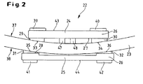
- FIG. 2 shows a detailed view of a clamping jaw in the position of a clamp on the hoop 23.
- the clamping jaw 22 consists of a first plate-shaped part 24, here the upper part, and a second plate-shaped part 25, here the lower part, which together form a clamp 26.
- the upper part is shorter than the lower part, seen along the tether, formed.
- two contact elements 29, 30 and 31, 32 are respectively mounted.
- the contact elements are made of rubber or a rubber-elastic plastic.
- contact elements or rubber pads with a curved surface 33, 34 and 35, 36 deform elastically in a state of tension and adapt to the radius of curvature of the inner or outer periphery 37, 38 of the hoop 23.
- Further contact elements 39, 40 and 41 and 42 are mounted on the upper side 43 of the upper part and on the lower side 44 of the lower part in order to use the upper as well as the lower part of both sides.
- the contact elements 41, 42 and the lower rubber pads stabilize the clamping claw on the ground.
- the first part 24 or upper part and the second part 25 or lower part are arranged on the hoop 23 so that they surround this clamp-like. They are then clamped by means of screws 45, 46 and 47, 48.
- screws 45, 46 and 47, 48 are provided for the fine adjustment (compare FIG. 3). It is clear in particular in Fig. 2 that due to the staggered points of contact of the rubber pads a tension-free clamping position of the clamping jaw is achieved.
- the clamp 26 of the clamping claw 22 has a recess 49 into which engaging means 50 of the pedal machine, here a rod 51 with a ball-shaped head 52, come into engagement.
- the design of the rod head 52 is not limited to a spherical shape; any other form that fulfills the function with a correspondingly shaped recess 49 of the clamping jaw 22 is also included in the invention.
- the recess 49 extends through the upper part and partially through the lower part.
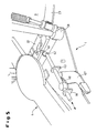
- the respective end faces 53, 54 of the upper and lower parts are processed so that a total of the entire Height of the clamping claw 22 results in a concave curvature or recess 55 (see in particular Fig. 4).
- the clamp 26 of the clamping claw 22 is divided into the region 26b clamped to the hoop 23 and the region 26a leading away from the hoop.
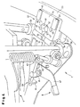
- the foot machine has, in addition to the engagement means 50, a quick-release closure 56.
- the quick release consists essentially of a return mechanism for the rod 51, which will be discussed below.
- the foot machine is provided with a contact rod 60 or axis, which extends between the bearing columns 10, 11 and the bearing column feet 58, 59 of the pedal.
- the contact rod 60 itself is surrounded by a jacket 61a, b of rubber or a corresponding rubber-elastic material.
- the contact rod 60 has centrally a passage opening 62 or a bore for the push rod 51, wherein at this point the jacket 61a, b is interrupted (see Fig .. 5).
- the return mechanism of the quick release 56 includes the additional center (63) and at its end facing away from the clamping claw end 64 slidably guided push rod.
- protruding from the bottom plate 8 guides 65, 66 are provided in the form of tabs with corresponding holes.
- the clamping jaw 22 pivot at a certain angle about this rod 60 or roll on the rod 60, so that inclinations of the bass drum 9 can be intercepted.
Landscapes
- Physics & Mathematics (AREA)
- Engineering & Computer Science (AREA)
- Acoustics & Sound (AREA)
- Multimedia (AREA)
- Auxiliary Devices For Music (AREA)
Claims (13)
- Griffe de serrage pour relier une pédale (1) pour des instruments à percussion avec une partie d'un anneau de tension circulaire (23) d'un instrument à percussion, notamment d'un tambour de basse (9), avec un crampon (26) comportant un premier élément (24), un deuxième élément (25) ainsi que des moyens pour tendre et détendre mutuellement le premier (24) et le deuxième élément (25), le premier élément (24) qui s'engage sur la face intérieure de l'anneau de tension (23) comportant par rapport au deuxième élément (25) qui s'engage sur la face extérieure de l'anneau de tension (23) des points de contact déportés vers l'intérieur pour l'application sur l'anneau de tension,
caractérisée en ce que les faces frontales (53, 54) dirigées vers la pédale du premier (24) et du deuxième élément (25) du crampon (26) comportent un évidement concave (55). - Griffe de serrage selon la revendication 1,
caractérisée en ce que le premier élément (24) est conçu avec de plus petites dimensions que le deuxième élément (25) dans son extension géométrique le long de l'anneau de tension. - Griffe de serrage selon la revendication 1 ou 2,
caractérisée en ce que les points de contact en tant qu'éléments de contact (29 à 32) sont en un matériau adaptable à la périphérie intérieure ou extérieure de l'anneau de tension (23), à l'état tendu. - Griffe de serrage selon la revendication 3,
caractérisée en ce que les éléments de contact (29 à 32) sont en caoutchouc ou en une matière plastique élastique. - Griffe de serrage selon la revendication 3,
caractérisée par des moyens pour la liaison amovible du crampon (26) monté sur l'anneau de tension (23) avec la pédale. - Griffe de serrage selon l'une quelconque des revendications 1 à 4,
caractérisée en ce que l'élément de crampon qui s'éloigne de l'anneau de tension (23) comporte un évidement (49) par lequel un moyen d'engagement (50) qui est disposé sur la pédale (1) vient s'engager. - Griffe de serrage selon l'une quelconque des revendications 1 à 6,
caractérisée en ce que les moyens pour tendre et pour détendre mutuellement le premier et le deuxième élément du crampon comportent des assemblages par vis (45 à 48). - Griffe de serrage selon l'une quelconque des revendications 1 à 7,
caractérisée par une partie supérieure en forme de plaque en tant que premier élément (24) avec deux éléments de contact (29, 30) sur sa face inférieure (27) venant s'appliquer sur l'anneau de tension (23), par une partie inférieure en forme de plaque en tant que deuxième élément (25) avec deux éléments de contact (31, 32) sur sa face supérieure (28) venant s'appliquer sur l'anneau de tension (23), dans la zone du crampon (26a) qui est opposée à l'anneau de tension, l'évidement (49) étant formé en fonction d'une extrémité sphérique d'une tige de poussée (51) de moyens d'engagement (50) de la pédale (51) et cette extrémité sphérique de la tige de poussée (51) étant posée dans cet évidement (49) pour assurer la liaison amovible, ainsi que par moins deux assemblages par vis (45 à 48), pour tendre la partie supérieure par rapport à la partie inférieure dans la position du crampon et pour l'ajuster. - Pédale destinée à être fixée sur un anneau de tension d'un instrument à percussion à l'aide d'une griffe de serrage selon l'une quelconque des revendications 1 à 8, comprenant un socle d'appui sur lequel au moins un battoir (2, 3) pouvant être déplacé au moyen d'un mécanisme d'actionnement (5, 6) pouvant être manoeuvré à l'aide d'une pédale (4) est maintenu de façon pivotante et des moyens d'engagement (50) pour la griffe de serrage (22), pouvant être montés de façon amovible sur l'anneau de tension (23), ainsi qu'une fermeture rapide (56), pour tendre les moyens d'engagement (50), par rapport à la griffe de serrage (22),
caractérisée en ce qu'entre des pieds de la colonne (58, 59) du socle d'appui est montée une barre de contact (60) qui s'étend entre les deux pieds de colonne (58, 59) et sur laquelle l'évidement concave (55) de la griffe de serrage est tiré lors du processus de tension et sur lequel la griffe de serrage (22) peut être pivotée sous un angle défini. - Pédale selon la revendication 9,
caractérisée en ce que les moyens d'engagement (50) comprennent une tige de poussée (51) dont la tête (52) dirigée vers l'anneau de tension (23) de l'instrument à percussion est façonnée sous forme sphérique et en ce que la fermeture rapide (56) comprend un mécanisme à levier pour déplacer la barre de poussée en direction de l'anneau de tension et retour. - Pédale selon la revendication 10,
caractérisée en ce que la barre de contact (60) est entourée d'une enveloppe (61a, 61b) en caoutchouc ou en matière plastique élastique. - Pédale selon l'une quelconque des revendications 9 à 11,
caractérisée en ce que la barre de poussée (51) s'étend le long d'une plaque de fond (8) de la pédale et en ce qu'elle est montée de façon déplaçable dans au moins un guidage (65, 66) et en ce qu'elle s'étend avec son extrémité dirigée vers la griffe de serrage à travers un orifice correspondant (62) dans la barre de contact (60) et en ce que la barre de poussée (51) est déplaçable le long de sa course de translation, par l'intermédiaire d'une plaque d'excentrique (68) engagée sur cette dernière, qui est reliée à un levier d'actionnement (67), pour obtenir la fermeture rapide de la griffe de serrage (22). - Pédale selon l'une quelconque des revendications 9 à 12, avec une griffe de serrage selon l'une quelconque des revendications 1 à 8.
Applications Claiming Priority (2)
| Application Number | Priority Date | Filing Date | Title |
|---|---|---|---|
| DE10109945A DE10109945A1 (de) | 2001-03-01 | 2001-03-01 | Spannklaue und Fußmaschine für Perkussions-Instrumente |
| DE10109945 | 2001-03-01 |
Publications (2)
| Publication Number | Publication Date |
|---|---|
| EP1237146A1 EP1237146A1 (fr) | 2002-09-04 |
| EP1237146B1 true EP1237146B1 (fr) | 2006-07-05 |
Family
ID=7675978
Family Applications (1)
| Application Number | Title | Priority Date | Filing Date |
|---|---|---|---|
| EP02004448A Expired - Lifetime EP1237146B1 (fr) | 2001-03-01 | 2002-02-27 | Dispositif pour fixer la pédale sur une grosse caise |
Country Status (3)
| Country | Link |
|---|---|
| US (1) | US6632990B2 (fr) |
| EP (1) | EP1237146B1 (fr) |
| DE (2) | DE10109945A1 (fr) |
Cited By (1)
| Publication number | Priority date | Publication date | Assignee | Title |
|---|---|---|---|---|
| DE102010046921B3 (de) * | 2010-09-29 | 2011-12-15 | Sonor Gmbh & Co. Kg | Fußmaschine von Perkussions-Instrumenten |
Families Citing this family (10)
| Publication number | Priority date | Publication date | Assignee | Title |
|---|---|---|---|---|
| US20060005689A1 (en) * | 2004-07-08 | 2006-01-12 | Fusamitsu Ito | Pedal coupling device and bass drum |
| US7262356B1 (en) * | 2006-04-18 | 2007-08-28 | Lukios Ii Charles Dean | Bass drum pedal hyper-beater |
| US7897858B1 (en) * | 2009-10-29 | 2011-03-01 | Tsun-Chi Liao | Drum rim clamping apparatus for a foot pedal hammer seat |
| US9240169B2 (en) | 2010-10-22 | 2016-01-19 | Drum Workshop, Inc. | Pivot supports for drum rim |
| US8330032B1 (en) * | 2010-10-22 | 2012-12-11 | Drum Workshop, Inc. | Pivot supports for drum rim |
| US10012261B2 (en) | 2011-09-26 | 2018-07-03 | Kenneth Alvin Jungeberg | Method and apparatus for releasably immobilizing an attachment to an external object |
| US9093053B2 (en) * | 2011-11-03 | 2015-07-28 | Kenneth Alvin Jungeberg | Arrestor for user operated devices |
| US9257106B2 (en) * | 2014-02-06 | 2016-02-09 | Ai-Musics Technology Inc. | Digital bass drum kick |
| US10504495B1 (en) | 2018-07-06 | 2019-12-10 | Daniel Pawlovich | Kick drum pedal clamp mechanism |
| CN110570831A (zh) * | 2019-07-25 | 2019-12-13 | 天津优尼柯乐器有限公司 | 一种便于移动的架子鼓 |
Family Cites Families (7)
| Publication number | Priority date | Publication date | Assignee | Title |
|---|---|---|---|---|
| US2446508A (en) * | 1945-05-17 | 1948-08-03 | H & A Selmer Inc | Drum pedal |
| US3426640A (en) * | 1965-02-09 | 1969-02-11 | Henry H Slingerland Jr | Quick connect pedal connector |
| DD285656A5 (de) * | 1989-07-11 | 1990-12-19 | Bethke,Harald,Dd | Pedalbetaetigte trommelschlegelvorrichtung |
| DK87495A (da) * | 1995-08-03 | 1997-02-04 | Peter Lundholm Jensen | Tromme og trommepedal dertil |
| US5726370A (en) * | 1995-12-29 | 1998-03-10 | Pearl Musical Instrument Co. | Hoop clamping system for a bass drum pedal assembly |
| GB9625401D0 (en) * | 1996-12-06 | 1997-01-22 | Premier Percussion Ltd | Drum beater device |
| US6011208A (en) * | 1999-01-11 | 2000-01-04 | Hoshino Gakki Kabushiki Kaisha | Drum hoop holding device for a drum pedal |
-
2001
- 2001-03-01 DE DE10109945A patent/DE10109945A1/de not_active Withdrawn
-
2002
- 2002-02-27 DE DE50207414T patent/DE50207414D1/de not_active Expired - Fee Related
- 2002-02-27 EP EP02004448A patent/EP1237146B1/fr not_active Expired - Lifetime
- 2002-02-28 US US10/085,629 patent/US6632990B2/en not_active Expired - Fee Related
Cited By (1)
| Publication number | Priority date | Publication date | Assignee | Title |
|---|---|---|---|---|
| DE102010046921B3 (de) * | 2010-09-29 | 2011-12-15 | Sonor Gmbh & Co. Kg | Fußmaschine von Perkussions-Instrumenten |
Also Published As
| Publication number | Publication date |
|---|---|
| US20020121178A1 (en) | 2002-09-05 |
| EP1237146A1 (fr) | 2002-09-04 |
| US6632990B2 (en) | 2003-10-14 |
| DE10109945A1 (de) | 2002-09-19 |
| DE50207414D1 (de) | 2006-08-17 |
Similar Documents
| Publication | Publication Date | Title |
|---|---|---|
| EP1237146B1 (fr) | Dispositif pour fixer la pédale sur une grosse caise | |
| DE3600062A1 (de) | Tragbare trommeleinheit | |
| DE60021161T2 (de) | Fensterverriegelungsmechanismus für motorisiertes Werkzeug | |
| DE10000728A1 (de) | Klammervorrichtung für Stangen | |
| DE19720375B4 (de) | Trommel-Schlagvorrichtung | |
| DE3510311A1 (de) | Einrichtung zur vertikalen und axialen einstellung der lage eines lenkrades | |
| DE19828888A1 (de) | Einrichtung für eine Schneidmaschine | |
| DE3830445C2 (fr) | ||
| EP1237145B1 (fr) | Dispositif à pédale pour une grosse caisse | |
| DE69800872T2 (de) | Vibrationsvorrichtung zur behandlung von einem bodenbelag | |
| DE4200924A1 (de) | Klammervorrichtung eines trommelpedals | |
| DE10126914A1 (de) | Abhebermechanismus für das Snareband einer Musiktrommel | |
| DE3503869A1 (de) | Spannvorrichtung fuer das trommelfell einer trommel | |
| DE4020794C2 (fr) | ||
| EP0425935A2 (fr) | Dispositif de mise en tension parallèle des plaques d'impression | |
| DE19963054C2 (de) | Fußpedalvorrichtung für ein Musikinstrument | |
| DE3420062A1 (de) | Pedalbetaetigte trommelschlegelvorrichtung | |
| EP4121339A1 (fr) | Sonnette à main et poignée de guidon comportant une sonnette à main | |
| DE102005060865A1 (de) | Befestigungsvorrichtung | |
| DE102022001003B4 (de) | Vorrichtung zur Erzeugung eines Schlagimpulses | |
| EP0683047B1 (fr) | Dispositif pour fixer une plaque d'impression | |
| DE69920163T2 (de) | Furnierschneidmaschine mit Druckbalken | |
| DE19635762C2 (de) | Einstellbarer Lenkervorbau für ein Fahrrad | |
| DE4416000B4 (de) | Befestigungseinrichtung für Trommeln | |
| DE19745693C2 (de) | Pauke |
Legal Events
| Date | Code | Title | Description |
|---|---|---|---|
| PUAI | Public reference made under article 153(3) epc to a published international application that has entered the european phase |
Free format text: ORIGINAL CODE: 0009012 |
|
| AK | Designated contracting states |
Kind code of ref document: A1 Designated state(s): AT BE CH CY DE DK ES FI FR GB GR IE IT LI LU MC NL PT SE TR |
|
| AX | Request for extension of the european patent |
Free format text: AL;LT;LV;MK;RO;SI |
|
| 17P | Request for examination filed |
Effective date: 20030220 |
|
| AKX | Designation fees paid |
Designated state(s): DE FR GB IT |
|
| 17Q | First examination report despatched |
Effective date: 20050513 |
|
| GRAP | Despatch of communication of intention to grant a patent |
Free format text: ORIGINAL CODE: EPIDOSNIGR1 |
|
| GRAS | Grant fee paid |
Free format text: ORIGINAL CODE: EPIDOSNIGR3 |
|
| GRAA | (expected) grant |
Free format text: ORIGINAL CODE: 0009210 |
|
| AK | Designated contracting states |
Kind code of ref document: B1 Designated state(s): DE FR GB IT |
|
| PG25 | Lapsed in a contracting state [announced via postgrant information from national office to epo] |
Ref country code: IT Free format text: LAPSE BECAUSE OF FAILURE TO SUBMIT A TRANSLATION OF THE DESCRIPTION OR TO PAY THE FEE WITHIN THE PRESCRIBED TIME-LIMIT;WARNING: LAPSES OF ITALIAN PATENTS WITH EFFECTIVE DATE BEFORE 2007 MAY HAVE OCCURRED AT ANY TIME BEFORE 2007. THE CORRECT EFFECTIVE DATE MAY BE DIFFERENT FROM THE ONE RECORDED. Effective date: 20060705 |
|
| REG | Reference to a national code |
Ref country code: GB Ref legal event code: FG4D Free format text: NOT ENGLISH |
|
| REF | Corresponds to: |
Ref document number: 50207414 Country of ref document: DE Date of ref document: 20060817 Kind code of ref document: P |
|
| GBT | Gb: translation of ep patent filed (gb section 77(6)(a)/1977) |
Effective date: 20061009 |
|
| ET | Fr: translation filed | ||
| PLBE | No opposition filed within time limit |
Free format text: ORIGINAL CODE: 0009261 |
|
| STAA | Information on the status of an ep patent application or granted ep patent |
Free format text: STATUS: NO OPPOSITION FILED WITHIN TIME LIMIT |
|
| 26N | No opposition filed |
Effective date: 20070410 |
|
| PGFP | Annual fee paid to national office [announced via postgrant information from national office to epo] |
Ref country code: IT Payment date: 20080223 Year of fee payment: 7 |
|
| PGFP | Annual fee paid to national office [announced via postgrant information from national office to epo] |
Ref country code: FR Payment date: 20080214 Year of fee payment: 7 |
|
| PGFP | Annual fee paid to national office [announced via postgrant information from national office to epo] |
Ref country code: DE Payment date: 20090219 Year of fee payment: 8 |
|
| PGFP | Annual fee paid to national office [announced via postgrant information from national office to epo] |
Ref country code: GB Payment date: 20090219 Year of fee payment: 8 |
|
| REG | Reference to a national code |
Ref country code: FR Ref legal event code: ST Effective date: 20091030 |
|
| PG25 | Lapsed in a contracting state [announced via postgrant information from national office to epo] |
Ref country code: FR Free format text: LAPSE BECAUSE OF NON-PAYMENT OF DUE FEES Effective date: 20090302 |
|
| GBPC | Gb: european patent ceased through non-payment of renewal fee |
Effective date: 20100227 |
|
| PG25 | Lapsed in a contracting state [announced via postgrant information from national office to epo] |
Ref country code: DE Free format text: LAPSE BECAUSE OF NON-PAYMENT OF DUE FEES Effective date: 20100901 |
|
| PG25 | Lapsed in a contracting state [announced via postgrant information from national office to epo] |
Ref country code: IT Free format text: LAPSE BECAUSE OF NON-PAYMENT OF DUE FEES Effective date: 20090227 Ref country code: GB Free format text: LAPSE BECAUSE OF NON-PAYMENT OF DUE FEES Effective date: 20100227 |