EP1237146B1 - Clamp for fixing a pedal device to a bass-drum - Google Patents
Clamp for fixing a pedal device to a bass-drum Download PDFInfo
- Publication number
- EP1237146B1 EP1237146B1 EP02004448A EP02004448A EP1237146B1 EP 1237146 B1 EP1237146 B1 EP 1237146B1 EP 02004448 A EP02004448 A EP 02004448A EP 02004448 A EP02004448 A EP 02004448A EP 1237146 B1 EP1237146 B1 EP 1237146B1
- Authority
- EP
- European Patent Office
- Prior art keywords
- hoop
- accordance
- tensioning
- foot machine
- tensioning clutch
- Prior art date
- Legal status (The legal status is an assumption and is not a legal conclusion. Google has not performed a legal analysis and makes no representation as to the accuracy of the status listed.)
- Expired - Lifetime
Links
- 238000009527 percussion Methods 0.000 claims description 13
- 230000007246 mechanism Effects 0.000 claims description 7
- 239000004033 plastic Substances 0.000 claims description 4
- 239000000463 material Substances 0.000 claims 1
- 238000000034 method Methods 0.000 claims 1
- 230000000717 retained effect Effects 0.000 claims 1
- 239000000126 substance Substances 0.000 claims 1
- 210000000078 claw Anatomy 0.000 description 19
- 238000010276 construction Methods 0.000 description 4
- NJPPVKZQTLUDBO-UHFFFAOYSA-N novaluron Chemical compound C1=C(Cl)C(OC(F)(F)C(OC(F)(F)F)F)=CC=C1NC(=O)NC(=O)C1=C(F)C=CC=C1F NJPPVKZQTLUDBO-UHFFFAOYSA-N 0.000 description 4
- 230000008901 benefit Effects 0.000 description 3
- 230000006378 damage Effects 0.000 description 3
- 230000002040 relaxant effect Effects 0.000 description 2
- 241000333074 Eucalyptus occidentalis Species 0.000 description 1
- 208000027418 Wounds and injury Diseases 0.000 description 1
- 230000001419 dependent effect Effects 0.000 description 1
- 238000011161 development Methods 0.000 description 1
- 230000018109 developmental process Effects 0.000 description 1
- 230000000694 effects Effects 0.000 description 1
- 239000013013 elastic material Substances 0.000 description 1
- 208000014674 injury Diseases 0.000 description 1
- 239000002184 metal Substances 0.000 description 1
- 239000002990 reinforced plastic Substances 0.000 description 1
- 230000000284 resting effect Effects 0.000 description 1
Images


Classifications
-
- G—PHYSICS
- G10—MUSICAL INSTRUMENTS; ACOUSTICS
- G10D—STRINGED MUSICAL INSTRUMENTS; WIND MUSICAL INSTRUMENTS; ACCORDIONS OR CONCERTINAS; PERCUSSION MUSICAL INSTRUMENTS; AEOLIAN HARPS; SINGING-FLAME MUSICAL INSTRUMENTS; MUSICAL INSTRUMENTS NOT OTHERWISE PROVIDED FOR
- G10D13/00—Percussion musical instruments; Details or accessories therefor
- G10D13/10—Details of, or accessories for, percussion musical instruments
- G10D13/11—Pedals; Pedal mechanisms
Definitions
- the invention relates to a clamping claw for connecting a percussion Instrurriente to a section of a circular tether of a percussion instrument, in particular a bass drum, with a clamp having a first part, a second part and means for bracing and relaxing the first and the second part against each other, wherein the first part, which engages the inside of the tether, with respect to the second part; which engages the outside of the clamping tire, offset inwardly disposed points of contact for resting on the hoop has. Furthermore, the invention relates to a corresponding pedestrian.
- Such pedals are used to quickly and accurately the drumming of a drummer on the percussion instrument, such as a bass drum, by means of a to transmit a pedal of the pedal operated Schlegel.
- the foot machine is usually attached to the hoop of the bass drum with a hook or a clamp that is firmly connected to the foot machine.
- Such clamps consist of an upper and lower clamp part, which are mounted on the hoops. With every dismantling or construction of the bass drum, this connection between the foot machine and hoop must be loosened or clamped again.
- the present invention seeks to provide a jaw of a pedemonic percussion instruments, which provides a simple and easy-to-handle connection to the hoop of a percussion instrument, without the - also consisting of delicate woods - hoop both in the assembly as especially in the clip position damage.
- the clamping jaw has an inwardly or concavely arched recess at its pointing to the foot machine end faces of the upper and the lower part of the clip, which is adapted approximately to the circumference of a contact rod.
- the clamping claw comes with its bulging end face on the contact rod to the support, which has the advantageous effect that the mounted on the bass drum clamping jaw is pivotable about the contact rod within a certain angle and thus possibly an inclination of the bass drum tension can be collected. In this way, tensions of the clamping claw are avoided on the hoop and counteracted injury to the woods.
- the curved end faces of the clamping jaw are provided with Leksriefen.
- the contact rod or axis of the pedestal is wrapped with a rubber sheath. Both features reinforce the advantageous gripping and pivoting function described above.
- the first part or the upper part of the clamp is designed to be smaller in its geometrical extension along the clamping strip relative to the second part or the lower part of the clamp in order to achieve the offset of the contact points.
- the contact points are formed as elastic contact elements, which automatically adapt to the respective radius of curvature of the outer and inner circumference of the bass drum in the state of tension.
- the contact elements are preferably made of rubber or a rubber-elastic plastic and counteract a Veschl impart the tether.
- the clamping claw is clamped independently of the pedestrian on the hoop and then connected to the pedestrian.
- the clamping jaw can remain even with a reduction or construction of the bass drum and only rarely must be removed from the hoop.
- a mutual clamping and relaxing or clamping of the first part or upper part and the second part or lower part of the clamp of the clamping jaw is preferably achieved by means of screw connections.
- four setscrews are preferably provided, namely two for the coarse adjustment and two for the fine adjustment, which in particular ensure that the clamp is tightened parallel to the hoop.
- an adjustment of the clamping jaw is possible even with differently designed hoop, for example, if this are different thicknesses.
- any existing distortion in the hoops can be compensated.
- the part of the bracket facing away from the hoop has a recess with which an engaging means arranged on the foot machine engages.
- suitable engaging means on the pedestal comprise a push rod whose head pointing to the hoop of the percussion instrument, for example, has a spherical shape.
- the push rod is moved by means of a lever mechanism in the direction of hoop and back and fixed the clamping claw on the pedals.
- the independent clamping claw is mounted on the rim of the bass drum in a first step.
- the ball-like end of the push rod is inserted into the correspondingly shaped recess of the clamping jaw. in this connection puts the clamping claw with its curved end face to the contact rod of the pedestal.
- the push rod is moved away from the clamping jaw and clamped in this way the clamping jaw against the pedals.
- a pedal machine 1 for percussion musical instruments shown in Fig. 1 is a double-foot machine with two mallets 2, 3, which are operated via a two-part foot pedal 4 with two different operating mechanisms 5, 6.
- the basic construction or stand construction 7 of the foot machine 1 consists of a base plate 8, on which two bearing pillars 10, 11 extending upwards approximately at right angles are arranged at their end 8a pointing towards the bass drum 9. While the right flail 2 is operated via the pedal drum 4a facing the bass drum and via this connecting rod 12b, which is arranged on a first shaft 13 with a reinforced plastic band 12a, the left flail 3 is moved over the rear pedal part 4b operated by means of a rod drive 14, which sets a second shaft 15 in a rotational movement.
- Clamping heads 16, 17 are arranged on both independently operating shafts 13, 15, in each of which the flails 2, 3 are held over the lower end of a shank 18, 19, the impact pad 20, 21 being arranged at its upper end.
- Such a foot machine 1 is attached via a clamping claw 22 to the circular hoop 23 of the bass drum 9 (shown only partially here).
- foot machine shown here is by way of example only; According to the invention, in principle, all known foot machines, for example single or double foot machines with or without diverting mechanism for a spaced foot pedal, in question, having the engagement means according to the invention and the quick release.
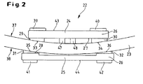
- FIG. 2 shows a detailed view of a clamping jaw in the position of a clamp on the hoop 23.
- the clamping jaw 22 consists of a first plate-shaped part 24, here the upper part, and a second plate-shaped part 25, here the lower part, which together form a clamp 26.
- the upper part is shorter than the lower part, seen along the tether, formed.
- two contact elements 29, 30 and 31, 32 are respectively mounted.
- the contact elements are made of rubber or a rubber-elastic plastic.
- contact elements or rubber pads with a curved surface 33, 34 and 35, 36 deform elastically in a state of tension and adapt to the radius of curvature of the inner or outer periphery 37, 38 of the hoop 23.
- Further contact elements 39, 40 and 41 and 42 are mounted on the upper side 43 of the upper part and on the lower side 44 of the lower part in order to use the upper as well as the lower part of both sides.
- the contact elements 41, 42 and the lower rubber pads stabilize the clamping claw on the ground.
- the first part 24 or upper part and the second part 25 or lower part are arranged on the hoop 23 so that they surround this clamp-like. They are then clamped by means of screws 45, 46 and 47, 48.
- screws 45, 46 and 47, 48 are provided for the fine adjustment (compare FIG. 3). It is clear in particular in Fig. 2 that due to the staggered points of contact of the rubber pads a tension-free clamping position of the clamping jaw is achieved.
- the clamp 26 of the clamping claw 22 has a recess 49 into which engaging means 50 of the pedal machine, here a rod 51 with a ball-shaped head 52, come into engagement.
- the design of the rod head 52 is not limited to a spherical shape; any other form that fulfills the function with a correspondingly shaped recess 49 of the clamping jaw 22 is also included in the invention.
- the recess 49 extends through the upper part and partially through the lower part.
- the respective end faces 53, 54 of the upper and lower parts are processed so that a total of the entire Height of the clamping claw 22 results in a concave curvature or recess 55 (see in particular Fig. 4).
- the clamp 26 of the clamping claw 22 is divided into the region 26b clamped to the hoop 23 and the region 26a leading away from the hoop.
- the foot machine has, in addition to the engagement means 50, a quick-release closure 56.
- the quick release consists essentially of a return mechanism for the rod 51, which will be discussed below.
- the foot machine is provided with a contact rod 60 or axis, which extends between the bearing columns 10, 11 and the bearing column feet 58, 59 of the pedal.
- the contact rod 60 itself is surrounded by a jacket 61a, b of rubber or a corresponding rubber-elastic material.
- the contact rod 60 has centrally a passage opening 62 or a bore for the push rod 51, wherein at this point the jacket 61a, b is interrupted (see Fig .. 5).
- the return mechanism of the quick release 56 includes the additional center (63) and at its end facing away from the clamping claw end 64 slidably guided push rod.
- protruding from the bottom plate 8 guides 65, 66 are provided in the form of tabs with corresponding holes.
- the clamping jaw 22 pivot at a certain angle about this rod 60 or roll on the rod 60, so that inclinations of the bass drum 9 can be intercepted.
Landscapes
- Physics & Mathematics (AREA)
- Engineering & Computer Science (AREA)
- Acoustics & Sound (AREA)
- Multimedia (AREA)
- Auxiliary Devices For Music (AREA)
Description
Die Erfindung betrifft eine Spannklaue zur Verbindung einer Fußmaschine für Perkussions-Instrurriente mit einem Abschnitt eines kreisförmigen Spannreifens eines Perkussions-Instrumentes, insbesondere einer Bass-Drum, mit einer Klammer, die einen ersten Teil, einen zweiten Teil sowie Mittel zum Verspannen und Entspannen des ersten und zweiten Teils gegeneinander aufweist, wobei der erste Teil, der an die Innenseite des Spannreifens angreift, gegenüber dem zweiten Teil; der an die Außenseite des Spannreifens angreift, nach innen versetzt angeordnete Berührungspunkte zum Aufliegen auf dem Spannreifen aufweist. Desweiteren betrifft die Erfindung eine entsprechende Fußmaschine.The invention relates to a clamping claw for connecting a percussion Instrurriente to a section of a circular tether of a percussion instrument, in particular a bass drum, with a clamp having a first part, a second part and means for bracing and relaxing the first and the second part against each other, wherein the first part, which engages the inside of the tether, with respect to the second part; which engages the outside of the clamping tire, offset inwardly disposed points of contact for resting on the hoop has. Furthermore, the invention relates to a corresponding pedestrian.
Derartige Fußmaschinen, wie gattungsgemäß durch die US-A-6.166.312 und/oder US-A-2-446.508 bekannt geworden, dienen dazu, das Fußspiel eines Schlagzeugers schnell und präzise auf das Schlaginstrument, beispielsweise eine Bass-Drum, mittels eines über ein Pedal der Fußmaschine betätigten Schlegels zu übertragen. Hierbei wird die Fußmaschine üblicherweise mit einem Haken oder einer Klammer, der bzw. die fest mit der Fußmaschine verbunden ist, an dem Spannreifen der Bass-Drum befestigt. Solche Klammern bestehen aus einem oberen und unteren Klammerteil, die an den Spannreifen montiert werden. Bei jedem Abbau oder Aufbau der Bass-Drum muß diese Verbindung zwischen Fußmaschine und Spannreifen gelöst bzw. wieder festgeklemmt werden.Such pedals, as known generically by US-A-6,166,312 and / or US-A-2-446,508, are used to quickly and accurately the drumming of a drummer on the percussion instrument, such as a bass drum, by means of a to transmit a pedal of the pedal operated Schlegel. In this case, the foot machine is usually attached to the hoop of the bass drum with a hook or a clamp that is firmly connected to the foot machine. Such clamps consist of an upper and lower clamp part, which are mounted on the hoops. With every dismantling or construction of the bass drum, this connection between the foot machine and hoop must be loosened or clamped again.
Die Spannreifen von Perkussions-Instrumenten, insbesondere von Bass-Drums, werden immer seltener aus Metall zugunsten von edlen, aber auch empfindlichen Hölzern hergestellt. Hierbei ergibt sich zwar der Vorteil eines wertvolleren Instrmentes, insbesondere was das ästhetische Empfinden betrifft, und eines besseren Klanges. Von Nachteil ist aber, daß gerade diese edlen Hölzer sehr bei der Montage der Klammern und durch die festgeklemmte Klammer bei einer Bewegung oder einem Abrutschen, beispielsweise bei einer Schrägstellung der Bass-Drum, leiden. Nicht selten sind Riefen, Kratzer oder sonstige Beschädigungen die Folge, die einerseits den ästhetischen Gesamteindruck stören, andererseits aber auch zu einer instabilen Bass-Drum-Anbindung führen.The hoops of percussion instruments, especially bass drums, are increasingly made of metal for the benefit of noble, but also delicate woods. Although this results in the advantage of a more valuable Instrmentes, especially as regards the aesthetic feeling, and a better sound. The disadvantage, however, that just these noble woods very much in the assembly of the brackets and by the clamp clamped in a movement or slipping, for example, in an inclination of the bass drum suffer. Not infrequently, scratches, scratches or other damage are the result, on the one hand disturb the overall aesthetic impression, but on the other hand also lead to an unstable bass drum connection.
Hiervon ausgehend liegt der Erfindung die Aufgabe zugrunde, eine Spannklaue einer Fußmaschine für Perkussions-Instrumente bereitzustellen, die eine einfache und gut handzuhabende Verbindung zu dem Spannreifen eines Perkussions-Instrumentes schafft, ohne den - auch aus empfindlichen Hölzern bestehenden - Spannreifen sowohl bei der Montage als auch vor allem in der Klammerstellung zu beschädigen.Proceeding from this, the present invention seeks to provide a jaw of a pedemonic percussion instruments, which provides a simple and easy-to-handle connection to the hoop of a percussion instrument, without the - also consisting of delicate woods - hoop both in the assembly as especially in the clip position damage.
Diese Aufgabe wird mittels der Spannklaue mit den Merkmalen des Anspruchs 1 gelöst. Eine mit einer solchen Spannklaue lösbar verbindbare Fußmaschine wird durch die Merkmale des Anspruchs 9 charakterisiert. Vorteilhafte Weiterentwicklungen sind in den Unteransprüchen beschrieben.This object is achieved by means of the clamping claw with the features of
Erfindungsgemäß wird vorgeschlagen, daß die Spannklaue an ihren zu der Fußmaschine weisenden Stirnseiten des Ober- und des Unterteils der Klammer eine nach innen bzw. konkav gewölbte Ausnehmung aufweist, die in etwa dem Umfang einer Kontaktstange angepaßt ist. Bei einem Schnellverschluß kommt die Spannklaue mit ihrer ausgewölbten Stirnseite an der Kontaktstange zur Auflage, was den vorteilhaften Effekt aufweist, daß die an der Bass-Drum montierte Spannklaue innerhalb eines bestimmten Winkels um die Kontaktstange herum schwenkbar ist und somit ggf. eine Schrägstellung der Bass-Drum spannungsfrei aufgefangen werden kann. Auf diese Weise werden Verspannungen der Spannklaue am Spannreifen vermieden und einer Verletzung der Hölzer entgegengewirkt.According to the invention it is proposed that the clamping jaw has an inwardly or concavely arched recess at its pointing to the foot machine end faces of the upper and the lower part of the clip, which is adapted approximately to the circumference of a contact rod. In a quick release, the clamping claw comes with its bulging end face on the contact rod to the support, which has the advantageous effect that the mounted on the bass drum clamping jaw is pivotable about the contact rod within a certain angle and thus possibly an inclination of the bass drum tension can be collected. In this way, tensions of the clamping claw are avoided on the hoop and counteracted injury to the woods.
Bevorzugt sind die gewölbten Stirnseiten der Spannklaue mit Längsriefen versehen. Die Kontaktstange bzw. -achse der Fußmaschine ist mit einem Gummimantel umhüllt. Beide Merkmale verstärken die oben beschriebene vorteilhafte Greif- und Verschwenkfunktion.Preferably, the curved end faces of the clamping jaw are provided with Längsriefen. The contact rod or axis of the pedestal is wrapped with a rubber sheath. Both features reinforce the advantageous gripping and pivoting function described above.
Vorzugsweise ist der erste Teil bzw. das Oberteil der Klammer gegenüber dem zweiten Teil bzw. dem Unterteil der Klammer in seiner geometrischen Ausdehnung längs des Spannreifens kleiner ausgebildet, um den Versatz der Berührungspunkte zu erreichen. Die Berührungspunkte sind als elastische Kontaktelemente ausgebildet, die sich im Verspannungszustand automatisch dem jeweiligen Krümmungsradius von Außen- und Innenumfang der Bass-Drum anpassen. Die Kontaktelemente bestehen vorzugsweise aus Gummi oder einem gummielastischen Kunststoff und wirken einem Veschleiß des Spannreifens entgegen.Preferably, the first part or the upper part of the clamp is designed to be smaller in its geometrical extension along the clamping strip relative to the second part or the lower part of the clamp in order to achieve the offset of the contact points. The contact points are formed as elastic contact elements, which automatically adapt to the respective radius of curvature of the outer and inner circumference of the bass drum in the state of tension. The contact elements are preferably made of rubber or a rubber-elastic plastic and counteract a Veschleiß the tether.
Nach der Erfindung wird die Spannklaue unabhängig von der Fußmaschine auf dem Spannreifen festgeklemmt und anschließend mit der Fußmaschine verbunden. In diesem festgeklemmten Zustand kann die Spannklaue selbst bei einem Abbau bzw. Aufbau der Bass-Drum verbleiben und muß nur noch selten von dem Spannreifen entfernt werden. Ein gegenseitiges Verspannen und Entspannen bzw. Festklemmen des ersten Teils bzw. Oberteils und des zweiten Teils bzw. Unterteils der Klammer der Spannklaue wird vorzugsweise mittels Schraubverbindungen erreicht. Nach einer bevorzugten Ausführungsform sind vorzugsweise vier Stellschrauben vorgesehen und zwar zwei für die Grobeinstellung und zwei für die Feinjustierung, die insbesondere gewährleisten, daß die Klammer parallel zum Spannreifen angezogen wird. Zudem wird eine Justierung der Spannklaue auch bei unterschiedlich ausgebildeten Spannreifen möglich, beispielsweise, wenn diese unterschiedlich dick sind. Zudem kann ein ggf. vorhandener Verzug im Spannreifen ausgeglichen werden.According to the invention, the clamping claw is clamped independently of the pedestrian on the hoop and then connected to the pedestrian. In this clamped state, the clamping jaw can remain even with a reduction or construction of the bass drum and only rarely must be removed from the hoop. A mutual clamping and relaxing or clamping of the first part or upper part and the second part or lower part of the clamp of the clamping jaw is preferably achieved by means of screw connections. According to a preferred embodiment, four setscrews are preferably provided, namely two for the coarse adjustment and two for the fine adjustment, which in particular ensure that the clamp is tightened parallel to the hoop. In addition, an adjustment of the clamping jaw is possible even with differently designed hoop, for example, if this are different thicknesses. In addition, any existing distortion in the hoops can be compensated.
Um eine einfache und leicht handzuhabende lösbare Verbindung der an den Spannreifen montierten Spannklaue mit der Fußmaschine zu erreichen, weist der von dem Spannreifen wegweisende Teil der Klammer eine Ausnehmung auf, mit der ein Eingriffsmittel, das an der Fußmaschine angeordnet ist, in Eingriff kommt. Durch einen Schnellverschluß wird die so mit der Fußmaschine verbundene Spannklaue an der Fußmaschine verspannt.In order to achieve a simple and easy-to-handle detachable connection of the clamping claw mounted on the hoop with the pedestal, the part of the bracket facing away from the hoop has a recess with which an engaging means arranged on the foot machine engages. By a quick release the so connected to the pedal machine jaw clamped to the pedals.
Hierfür geeignete Eingriffsmittel an der Fußmaschine umfassen eine Schubstange, deren zu dem Spannreifen des Perkussions-Instrumentes weisender Kopf beispielsweise kugelartig ausgeformt ist. Die Schubstange wird mittels einer Hebelmechanik in Richtung Spannreifen und zurück verstellt und die Spannklaue an der Fußmaschine befestigt.For this purpose, suitable engaging means on the pedestal comprise a push rod whose head pointing to the hoop of the percussion instrument, for example, has a spherical shape. The push rod is moved by means of a lever mechanism in the direction of hoop and back and fixed the clamping claw on the pedals.
Nach einer besonders bevorzugten Weiterbildung der Erfindung weist die Fußmaschine zwischen Säulenfüßen des Lagersockels eine Kontaktstange auf, die sich zwischen den beiden Säulenfüßen erstreckt.According to a particularly preferred embodiment of the invention, the foot machine between column feet of the bearing base on a contact rod which extends between the two column feet.
Zur Verbindung der Fußmaschine mit einer Bass-Drum wird in einem ersten Schritt die unabhängige Spannklaue an dem Spannreifen der Bass-Drum montiert. In einem zweiten Schritt wird das kugelartig ausgebildete Ende der Schubstange in die entsprechend ausgeformte Ausnehmung der Spannklaue eingelegt. Hierbei legt sich die Spannklaue mit ihrer gewölbten Stirnseite an die Kontaktstange der Fußmaschine an. Mittels des Schnellverschlusses bzw. eines Hebelmechanismusses wird die Schubstange von der Spannklaue weg bewegt und auf diese Weise die Spannklaue gegenüber der Fußmaschine verspannt.To connect the pedals with a bass drum, the independent clamping claw is mounted on the rim of the bass drum in a first step. In a second step, the ball-like end of the push rod is inserted into the correspondingly shaped recess of the clamping jaw. in this connection puts the clamping claw with its curved end face to the contact rod of the pedestal. By means of the quick release or a Hebelmechanismusses the push rod is moved away from the clamping jaw and clamped in this way the clamping jaw against the pedals.
Weitere Einzelheiten und Vorteile der Erfindung ergeben sich aus den Unteransprüchen und aus der nachfolgenden Beschreibung, in der die in den Figuren dargestellten Ausführungsformen der Erfindung näher erläutert werden. Dabei sind neben den oben aufgeführten Kombinationen von Merkmalen auch Merkmale alleine oder in anderen Kombinationen erfindungswesentlich. Es zeigen:
- Fig. 1
- einen Überblick über eine Fußmaschine für Perkussions-Musikinstrumente, die mittels einer Spannklaue an dem Spannreifen einer Bass-Drum befestigt ist;
- Fig. 2
- eine Seitenansicht einer Spannklaue in Klammerstellung auf einem Spannreifen, von der Bass-Drum gesehen;
- Fig. 3
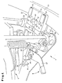
- einen Ausschnitt einer Fußmaschine nach Fig. 1 mit einer Spannklaue in Klammerstellung auf einem Spannreifen während eines ersten Schritts des Befestigungsvorgangs;
- Fig. 4
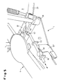
- einen Ausschnitt einer Fußmaschine nach Fig. 1 mit einer Spannklaue während eines zweiten Schritts des Befestigungsvorgangs;
- Fig. 5
- einen Ausschnitt einer Fußmaschine nach Fig. 1 mit einer Spannklaue während eines dritten Schritts des Befestigungsvorgangs.
- Fig. 1
- an overview of a foot machine for percussion musical instruments, which is attached by means of a clamping claw on the hoop of a bass drum;
- Fig. 2
- a side view of a clamping claw in stapling position on a hoop, seen from the bass drum;
- Fig. 3
- a detail of a foot machine of Figure 1 with a clamping claw in stapling position on a hoop during a first step of the fastening operation.
- Fig. 4
- a detail of a foot machine of Figure 1 with a clamping jaw during a second step of the fastening operation.
- Fig. 5
- a section of a foot machine according to Fig. 1 with a clamping jaw during a third step of the fastening operation.
Bei der in Fig. 1 dargestellten Ausführungsform einer Fußmaschine 1 für Perkussions-Musikinstrumente handelt es sich um eine Doppel-Fußmaschine mit zwei Schlegeln 2, 3, die über ein zweigeteiltes Fußpedal 4 mit zwei unterschiedlichen Betätigungsmechanismen 5, 6 bedient werden. Die Grundkonstruktion oder Ständerkonstruktion 7 der Fußmaschine 1 besteht aus einer Bodenplatte 8, an der an ihrem zu der Bass-Drum 9 hinweisenden Ende 8a zwei sich nach oben etwa rechtwinklig erstreckende Lagersäulen 10, 11 angeordnet sind. Während der rechte Schlegel 2 über den zur Bass-Drum hinweisenden Pedalteil 4a und über diesen mit einem verstärkten Kunststoffband 12a zusammenwirkenden Pleuel 12b, das über eine Buchse auf einer ersten Welle 13 angeordnet ist, bedient wird, wird der linke Schlegel 3 über den hinteren Pedalteil 4b mittels eines Stangentriebs 14, der eine zweite Welle 15 in eine Drehbewegung versetzt, bedient. Auf beiden unabhängig arbeitenden Wellen 13, 15 sind über Buchsen Klemmköpfe 16, 17 angeordnet, in denen jeweils der Schlegel 2, 3 über das untere Ende eines Schaftes 18, 19 gehalten wird, wobei an dessen oberen Ende das Schlagpolster 20, 21 angeordnet ist. Eine solche Fußmaschine 1 wird über eine Spannklaue 22 an dem kreisförmigen Spannreifen 23 der Bass- Drum 9 (hier nur teilweise dargestellt) befestigt.In the embodiment of a
Die hier gezeigte spezielle Ausführungsform der Fußmaschine dient nur als Beispiel; erfindungsgemäß kommen grundsätzlich alle bekannten Fußmaschinen, zum Beispiel Einzel- oder Doppel-Fußmaschinen mit oder ohne Ableitmechanik für ein beabstandet angeordnetes Fußpedal, in Frage, die die erfindungsgemäßen Eingriffsmittel sowie den Schnellverschluß aufweisen.The particular embodiment of the foot machine shown here is by way of example only; According to the invention, in principle, all known foot machines, for example single or double foot machines with or without diverting mechanism for a spaced foot pedal, in question, having the engagement means according to the invention and the quick release.
Eine Detailansicht einer Spannklaue in Klammerstellung an dem Spannreifen 23 zeigt Fig. 2. Die Spannklaue 22 besteht aus einem ersten plattenförmigen Teil 24, hier das Oberteil, und einem zweiten plattenförmigen Teil 25, hier das Unterteil, die zusammen eine Klammer 26 bilden. Das Oberteil ist kürzer als das Unterteil, gesehen längs des Spannreifens, ausgebildet. An der Unterseite 27 des Oberteils und an der Oberseite 28 des Unterteils sind jeweils zwei Kontaktelemente 29, 30 sowie 31, 32 angebracht. Die Kontaktelemente bestehen aus Gummi oder einem entsprechenden gummielastischen Kunststoff. Diese Kontaktelemente oder Gummipads mit gewölbter Oberfläche 33, 34 sowie 35, 36 verformen sich elastisch bei einem Verspannungszustand und passen sich an den Krümmungsradius des Innen- bzw. Außenumfangs 37, 38 des Spannreifens 23 an. Weitere Kontaktelemente 39, 40 sowie 41 und 42 sind auf der Oberseite 43 des Oberteils und auf der Unterseite 44 des Unterteils angebracht, um das Ober- wie das Unterteil von beiden Seiten benutzen zu können. Zudem stabilisieren die Kontaktelemente 41, 42 bzw. die unteren Gummipads die Spannklaue am Boden.FIG. 2 shows a detailed view of a clamping jaw in the position of a clamp on the
Zum Einstellen der Klammerstellung werden das erste Teil 24 bzw. Oberteil und das zweite Teil 25 bzw. Unterteil so an dem Spannreifen 23 angeordnet, daß sie diesen klammerartig umgreifen. Anschließend werden sie mittels Stellschrauben 45, 46 sowie 47, 48 verspannt. Bei der gezeigten Ausführungsform sind zwei Stellschrauben 45, 46 für die Grobjustierung sowie zwei Stellschrauben 47, 48 für die Feinjustierung vorgesehen (vgl. Fig. 3). Es wird insbesondere in Fig. 2 deutlich, daß aufgrund der versetzten Berührungspunkte der Gummipads eine spannungsfreie Klammerstellung der Spannklaue erreicht wird.To adjust the staple position, the
Für eine lösbare Verbindung mit der Fußmaschine 1 weist die Klammer 26 der Spannklaue 22 eine Ausnehmung 49 auf, in die Eingriffsmittel 50 der Fußmaschine, hier eine Stange 51 mit einem kugelartig ausgeformten Kopf 52, in Eingriff kommen. Dabei ist die Ausbildung des Stangenkopfes 52 nicht auf eine Kugelform beschränkt; jede andere Form, die die Funktion mit einer entsprechend geformten Ausnehmung 49 der Spannklaue 22 erfüllt, ist ebenfalls von der Erfindung umfaßt.For a detachable connection with the
Bei dem gezeigten Ausführungsbeispiel erstreckt sich die Ausnehmung 49 durch das Oberteil und teilweise durch das Unterteil. Die jeweiligen Stirnseiten 53, 54 des Ober- und Unterteils sind so bearbeitet, daß sich insgesamt über die gesamte Höhe der Spannklaue 22 eine konkave Wölbung bzw. Ausnehmung 55 ergibt (vgl. hier insbesondere die Fig. 4). Die Klammer 26 der Spannklaue 22 unterteilt sich in den an den Spannreifen 23 festgeklemmten Bereich 26b sowie den von dem Spannreifen wegweisenden Bereich 26a.In the embodiment shown, the
Zur Befestigung mit einer so ausgebildeten Spannklaue 22 weist die Fußmaschine neben den Eingriffsmitteln 50 einen Schnellverschluß 56 auf. Der Schnellverschluß besteht im wesentlichen aus einer Rückstellmechanik für die Stange 51, auf die weiter unten eingegangen wird.For fastening with a clamping
Die Fußmaschine ist mit einer Kontaktstange 60 bzw. -achse versehen, die sich zwischen den Lagersäulen 10, 11 bzw. den Lagersäulenfüßen 58, 59 der Fußmaschine erstreckt. Die Kontaktstange 60 selbst ist mit einem Mantel 61a,b aus Gummi oder einem entsprechenden gummielastischen Material umgeben. Die Kontaktstange 60 weist mittig eine Durchlaßöffnung 62 bzw. eine Bohrung für die Schubstange 51 auf, wobei an dieser Stelle der Mantel 61a,b unterbrochen ist (vgl. Fig. 5).The foot machine is provided with a
Die Rückstellmechanik des Schnellverschlusses 56 umfaßt die zusätzlich mittig (63) sowie an ihrem von der Spannklaue wegweisenden Ende 64 verschiebbar geführte Schubstange. Hierzu sind aus der Bodenplatte 8 herausspringende Führungen 65, 66 in Form von Laschen mit entsprechenden Bohrungen vorgesehen. Mittels eines um einen Fixierpunkt verschwenkbaren Hebels 67 wird die Schubstange 51 über eine an dem Hebel 67 befestigte Exzenterscheibe 68 längs der Bodenplatte 8 verschoben.The return mechanism of the
Bei der Montage wird die Schubstange 51 mit ihrem kugelartigen Ende 52 bei gelöstem Schnellverschluß in die entsprechende Ausnehmung 49 der Spannklaue 22 von oben eingelegt (siehe Pfeil in Fig. 3). Hierdurch kommt die Spannklaue 22 mit ihren gewölbten Stirnseiten 53, 54 zur Anlage an die Kontaktstange 60 der Fußmaschine. Diese Position zeigt Fig. 4. Durch Verschwenken des Hebels 67 und somit Betätigen des Schnellverschlusses 56 wird die Schubstange 51 und damit der Kopf 52 zurückbewegt und die Spannklaue 22 gegenüber der Fußmaschine 1 bzw. der Kontaktstange 60 verspannt. Aufgrund der an den Umfang der ummantelten Kontaktstange 60 angepaßten Auswölbung 55 der Stirnseiten 53, 54 des Ober- und Unterteils kann die Spannklaue 22 in einem bestimmten Winkel um diese Stange schwenken 60 bzw. an der Stange 60 abrollen, so daß Schrägstellungen der Bass-Drum 9 abgefangen werden können.When mounting the
Claims (13)
- A tensioning clutch for connecting a foot machine (1) for percussion instruments with a section of a circular hoop (23) of a percussion instrument, particularly a bass drum (9), with a clamp (26) having a first part (24), a second part (25) and means for tensioning and slackening the first (24) and second parts (25) with respect to each other, wherein the first part (24), which attaches to the inner side of the hoop (23), has contact points that face the second part (25), which attaches to the outer side of the hoop, and are arranged to be inwardly offset for bearing on the hoop (23),
characterised in that
the frontal faces (53, 54) of the first (24) and second parts (25) of the clamp (26) that face towards the foot machine are conformed with a concave recess (55). - The tensioning clutch in accordance with claim 1,
characterised in that
the first part (24) is shaped such that its geometrical extension along the hoop is smaller than that of the second part (25). - The tensioning clutch in accordance with either of claims 1 or 2,
characterised in that
the contact points are conformed as contact elements (29-32) made from a material that is adaptable to the inner and outer circumference of the hoop (23) in the tensioned condition. - The tensioning clutch in accordance with claim 3,
characterised in that
the contact elements (29-32) are made from rubber or a rubber elastic plastic substance. - The tensioning clutch in accordance with any of claims 1 to 4,
characterised by
means for detachably connecting the clamp (26) mounted on the hoop (23) to the foot machine. - The tensioning clutch in accordance with claim 5,
characterised in that
the clamp element facing away from the hoop (23) includes a recess (49) in which an engaging means (50) arranged on the foot machine (1) engages. - The tensioning clutch in accordance with any of claims 1 to 6,
characterised in that
the means for mutual tensioning and slackening of the first and second parts of the clamp include threaded connections (45-48). - The tensioning clutch in accordance with any of claims 1 to 7,
characterised by
a plate-shaped upper part as the first part (24) with two contact elements (29, 30) on the underside (27) of which that bears on the hoop, a plate-shaped lower part as the second part (25) with two contact elements (31, 32) on the upper side (28) of which that bears on the hoop, wherein the recess (49) is formed in the clamp area (26 a) facing away from the hoop by engaging means (50) of the foot machine (1) corresponding to a ball-like end of a push rod (51), and this ball-like end of the push rod (51) is inserted in this recess (49) to create a detachable connection, and at least two threaded connections (45-48) to enable the upper part to be tensioned and adjusted with respect to the lower part in the clamped position. - A foot machine for securing to a hoop of a percussion instrument via tensioning clutch in accordance with any of claims 1 to 8, including a bearing base on which at least one beater (2, 3) is retained in pivoting manner, and which is movable via an operating mechanism (5, 6) actuated by a pedal (4), and engaging means (5) for the tensioning clutch (22), which is attachable in detachable manner to the hoop (23), and a quick release fastener(56) for tensioning the engaging means (50) with respect to the tensioning clutch (22),
characterised in that
a contact bar (60) is mounted between column feet (58, 59) of the bearing base, extending between the two column feet (58, 59), and is drawn towards the concave recess (55) of the tensioning clutch during the tensioning process, and against which the tensioning clutch (22) is pivotable through a certain angle. - The foot machine in accordance with claim 9,
characterised in that
the engaging means (50) include a push rod (51), the head (52) of which that is closest to the hoop (23) of the percussion instrument is in the shape of a ball, and that the quick release fastener (56) includes a lever mechanism for displacing the push rod towards and away from the hoop. - The foot machine in accordance with claim 10,
characterised in that
the contact bar (60) is enclosed in a sheath (61 a, 61 b) of rubber or a rubber elastic plastic. - The foot machine in accordance with any of claims 9 to 11,
characterised in that
the push rod (51) extends along a base plate (8) of the foot machine and is mounted so as to be movable on the base plate (8) in at least one guide (65, 66), and the end of closest to the tensioning clutch extends through a corresponding aperture (62) in the contact bar (60), and that the push rod (51) is movable along its travel path to reach the quick release fastener of the tensioning clutch (22) by pivoting of the actuating lever (67) via an eccentric cam (68) that engages in the push rod and is connected to an actuating lever (67). - The foot machine in accordance with any of claims 9 to 12 including a tensioning clutch in accordance with any of claims 1 to 8.
Applications Claiming Priority (2)
| Application Number | Priority Date | Filing Date | Title |
|---|---|---|---|
| DE10109945A DE10109945A1 (en) | 2001-03-01 | 2001-03-01 | Clamping claw and foot pedal for percussion instruments |
| DE10109945 | 2001-03-01 |
Publications (2)
| Publication Number | Publication Date |
|---|---|
| EP1237146A1 EP1237146A1 (en) | 2002-09-04 |
| EP1237146B1 true EP1237146B1 (en) | 2006-07-05 |
Family
ID=7675978
Family Applications (1)
| Application Number | Title | Priority Date | Filing Date |
|---|---|---|---|
| EP02004448A Expired - Lifetime EP1237146B1 (en) | 2001-03-01 | 2002-02-27 | Clamp for fixing a pedal device to a bass-drum |
Country Status (3)
| Country | Link |
|---|---|
| US (1) | US6632990B2 (en) |
| EP (1) | EP1237146B1 (en) |
| DE (2) | DE10109945A1 (en) |
Cited By (1)
| Publication number | Priority date | Publication date | Assignee | Title |
|---|---|---|---|---|
| DE102010046921B3 (en) * | 2010-09-29 | 2011-12-15 | Sonor Gmbh & Co. Kg | Pedal for bass drum, has column swivelably pivoted on base plate and cooperated with locking and unlocking unit, where pedal is connected with portion of circular rim of bass drum and column is formed with hub-like socket |
Families Citing this family (10)
| Publication number | Priority date | Publication date | Assignee | Title |
|---|---|---|---|---|
| US20060005689A1 (en) * | 2004-07-08 | 2006-01-12 | Fusamitsu Ito | Pedal coupling device and bass drum |
| US7262356B1 (en) * | 2006-04-18 | 2007-08-28 | Lukios Ii Charles Dean | Bass drum pedal hyper-beater |
| US7897858B1 (en) * | 2009-10-29 | 2011-03-01 | Tsun-Chi Liao | Drum rim clamping apparatus for a foot pedal hammer seat |
| US9240169B2 (en) | 2010-10-22 | 2016-01-19 | Drum Workshop, Inc. | Pivot supports for drum rim |
| US8330032B1 (en) * | 2010-10-22 | 2012-12-11 | Drum Workshop, Inc. | Pivot supports for drum rim |
| US10012261B2 (en) | 2011-09-26 | 2018-07-03 | Kenneth Alvin Jungeberg | Method and apparatus for releasably immobilizing an attachment to an external object |
| US9093053B2 (en) * | 2011-11-03 | 2015-07-28 | Kenneth Alvin Jungeberg | Arrestor for user operated devices |
| US9257106B2 (en) * | 2014-02-06 | 2016-02-09 | Ai-Musics Technology Inc. | Digital bass drum kick |
| US10504495B1 (en) | 2018-07-06 | 2019-12-10 | Daniel Pawlovich | Kick drum pedal clamp mechanism |
| CN110570831A (en) * | 2019-07-25 | 2019-12-13 | 天津优尼柯乐器有限公司 | Drum kit convenient to move |
Family Cites Families (7)
| Publication number | Priority date | Publication date | Assignee | Title |
|---|---|---|---|---|
| US2446508A (en) * | 1945-05-17 | 1948-08-03 | H & A Selmer Inc | Drum pedal |
| US3426640A (en) * | 1965-02-09 | 1969-02-11 | Henry H Slingerland Jr | Quick connect pedal connector |
| DD285656A5 (en) * | 1989-07-11 | 1990-12-19 | Bethke,Harald,Dd | PEDALED DRUM HINGE DEVICE |
| DK87495A (en) * | 1995-08-03 | 1997-02-04 | Peter Lundholm Jensen | Drum and drum pedal therefor |
| US5726370A (en) * | 1995-12-29 | 1998-03-10 | Pearl Musical Instrument Co. | Hoop clamping system for a bass drum pedal assembly |
| GB9625401D0 (en) * | 1996-12-06 | 1997-01-22 | Premier Percussion Ltd | Drum beater device |
| US6011208A (en) * | 1999-01-11 | 2000-01-04 | Hoshino Gakki Kabushiki Kaisha | Drum hoop holding device for a drum pedal |
-
2001
- 2001-03-01 DE DE10109945A patent/DE10109945A1/en not_active Withdrawn
-
2002
- 2002-02-27 DE DE50207414T patent/DE50207414D1/en not_active Expired - Fee Related
- 2002-02-27 EP EP02004448A patent/EP1237146B1/en not_active Expired - Lifetime
- 2002-02-28 US US10/085,629 patent/US6632990B2/en not_active Expired - Fee Related
Cited By (1)
| Publication number | Priority date | Publication date | Assignee | Title |
|---|---|---|---|---|
| DE102010046921B3 (en) * | 2010-09-29 | 2011-12-15 | Sonor Gmbh & Co. Kg | Pedal for bass drum, has column swivelably pivoted on base plate and cooperated with locking and unlocking unit, where pedal is connected with portion of circular rim of bass drum and column is formed with hub-like socket |
Also Published As
| Publication number | Publication date |
|---|---|
| US20020121178A1 (en) | 2002-09-05 |
| EP1237146A1 (en) | 2002-09-04 |
| US6632990B2 (en) | 2003-10-14 |
| DE10109945A1 (en) | 2002-09-19 |
| DE50207414D1 (en) | 2006-08-17 |
Similar Documents
| Publication | Publication Date | Title |
|---|---|---|
| EP1237146B1 (en) | Clamp for fixing a pedal device to a bass-drum | |
| DE3600062A1 (en) | PORTABLE DRUM UNIT | |
| DE60021161T2 (en) | Window locking mechanism for motorized tool | |
| DE10000728A1 (en) | Clamping device for bars | |
| DE19720375B4 (en) | Drum beater | |
| DE3510311A1 (en) | DEVICE FOR VERTICAL AND AXIAL ADJUSTMENT OF THE POSITION OF A STEERING WHEEL | |
| DE19828888A1 (en) | Hand held circular saw with off-centre blade drive and e.g. hydraulic motor | |
| DE3830445C2 (en) | ||
| EP1237145B1 (en) | Pedal device for a bass-drum | |
| DE69800872T2 (en) | VIBRATION DEVICE FOR TREATING A FLOORING | |
| DE4200924A1 (en) | Clamping device for pedal of bass percussion drum - comprises rotatable clamp with relatively pivotable jaw exerting grip on collar of drum irrespective of thickness | |
| DE10126914A1 (en) | Lifting mechanism for the snare band of a music drum | |
| DE3503869A1 (en) | TENSIONING DEVICE FOR THE DRUM SKIN OF A DRUM | |
| DE4020794C2 (en) | ||
| EP0425935A2 (en) | Device for the parallel tensioning of printing plates | |
| DE19963054C2 (en) | Foot pedal device for a musical instrument | |
| DE3420062A1 (en) | PEDAL ACTUATED DRUM BEATER | |
| EP4121339A1 (en) | Bell and handlebar grip having a bell | |
| DE102005060865A1 (en) | fastening device | |
| DE102022001003B4 (en) | Device for generating a shock pulse | |
| EP0683047B1 (en) | Device for mounting a printing plate | |
| DE69920163T2 (en) | Veneer cutting machine with pressure bar | |
| DE19635762C2 (en) | Adjustable handlebar stem for a bicycle | |
| DE4416000B4 (en) | Fastening device for drums | |
| DE19745693C2 (en) | Timpani |
Legal Events
| Date | Code | Title | Description |
|---|---|---|---|
| PUAI | Public reference made under article 153(3) epc to a published international application that has entered the european phase |
Free format text: ORIGINAL CODE: 0009012 |
|
| AK | Designated contracting states |
Kind code of ref document: A1 Designated state(s): AT BE CH CY DE DK ES FI FR GB GR IE IT LI LU MC NL PT SE TR |
|
| AX | Request for extension of the european patent |
Free format text: AL;LT;LV;MK;RO;SI |
|
| 17P | Request for examination filed |
Effective date: 20030220 |
|
| AKX | Designation fees paid |
Designated state(s): DE FR GB IT |
|
| 17Q | First examination report despatched |
Effective date: 20050513 |
|
| GRAP | Despatch of communication of intention to grant a patent |
Free format text: ORIGINAL CODE: EPIDOSNIGR1 |
|
| GRAS | Grant fee paid |
Free format text: ORIGINAL CODE: EPIDOSNIGR3 |
|
| GRAA | (expected) grant |
Free format text: ORIGINAL CODE: 0009210 |
|
| AK | Designated contracting states |
Kind code of ref document: B1 Designated state(s): DE FR GB IT |
|
| PG25 | Lapsed in a contracting state [announced via postgrant information from national office to epo] |
Ref country code: IT Free format text: LAPSE BECAUSE OF FAILURE TO SUBMIT A TRANSLATION OF THE DESCRIPTION OR TO PAY THE FEE WITHIN THE PRESCRIBED TIME-LIMIT;WARNING: LAPSES OF ITALIAN PATENTS WITH EFFECTIVE DATE BEFORE 2007 MAY HAVE OCCURRED AT ANY TIME BEFORE 2007. THE CORRECT EFFECTIVE DATE MAY BE DIFFERENT FROM THE ONE RECORDED. Effective date: 20060705 |
|
| REG | Reference to a national code |
Ref country code: GB Ref legal event code: FG4D Free format text: NOT ENGLISH |
|
| REF | Corresponds to: |
Ref document number: 50207414 Country of ref document: DE Date of ref document: 20060817 Kind code of ref document: P |
|
| GBT | Gb: translation of ep patent filed (gb section 77(6)(a)/1977) |
Effective date: 20061009 |
|
| ET | Fr: translation filed | ||
| PLBE | No opposition filed within time limit |
Free format text: ORIGINAL CODE: 0009261 |
|
| STAA | Information on the status of an ep patent application or granted ep patent |
Free format text: STATUS: NO OPPOSITION FILED WITHIN TIME LIMIT |
|
| 26N | No opposition filed |
Effective date: 20070410 |
|
| PGFP | Annual fee paid to national office [announced via postgrant information from national office to epo] |
Ref country code: IT Payment date: 20080223 Year of fee payment: 7 |
|
| PGFP | Annual fee paid to national office [announced via postgrant information from national office to epo] |
Ref country code: FR Payment date: 20080214 Year of fee payment: 7 |
|
| PGFP | Annual fee paid to national office [announced via postgrant information from national office to epo] |
Ref country code: DE Payment date: 20090219 Year of fee payment: 8 |
|
| PGFP | Annual fee paid to national office [announced via postgrant information from national office to epo] |
Ref country code: GB Payment date: 20090219 Year of fee payment: 8 |
|
| REG | Reference to a national code |
Ref country code: FR Ref legal event code: ST Effective date: 20091030 |
|
| PG25 | Lapsed in a contracting state [announced via postgrant information from national office to epo] |
Ref country code: FR Free format text: LAPSE BECAUSE OF NON-PAYMENT OF DUE FEES Effective date: 20090302 |
|
| GBPC | Gb: european patent ceased through non-payment of renewal fee |
Effective date: 20100227 |
|
| PG25 | Lapsed in a contracting state [announced via postgrant information from national office to epo] |
Ref country code: DE Free format text: LAPSE BECAUSE OF NON-PAYMENT OF DUE FEES Effective date: 20100901 |
|
| PG25 | Lapsed in a contracting state [announced via postgrant information from national office to epo] |
Ref country code: IT Free format text: LAPSE BECAUSE OF NON-PAYMENT OF DUE FEES Effective date: 20090227 Ref country code: GB Free format text: LAPSE BECAUSE OF NON-PAYMENT OF DUE FEES Effective date: 20100227 |