EP1234699A2 - Herstellung eines Cabriolet-Verdecks - Google Patents
Herstellung eines Cabriolet-Verdecks Download PDFInfo
- Publication number
- EP1234699A2 EP1234699A2 EP02001733A EP02001733A EP1234699A2 EP 1234699 A2 EP1234699 A2 EP 1234699A2 EP 02001733 A EP02001733 A EP 02001733A EP 02001733 A EP02001733 A EP 02001733A EP 1234699 A2 EP1234699 A2 EP 1234699A2
- Authority
- EP
- European Patent Office
- Prior art keywords
- frame area
- window
- disc
- pane
- convertible top
- Prior art date
- Legal status (The legal status is an assumption and is not a legal conclusion. Google has not performed a legal analysis and makes no representation as to the accuracy of the status listed.)
- Granted
Links
- 238000004519 manufacturing process Methods 0.000 title description 2
- HZRSNVGNWUDEFX-UHFFFAOYSA-N pyraclostrobin Chemical compound COC(=O)N(OC)C1=CC=CC=C1COC1=NN(C=2C=CC(Cl)=CC=2)C=C1 HZRSNVGNWUDEFX-UHFFFAOYSA-N 0.000 title 1
- 238000000034 method Methods 0.000 claims abstract description 7
- 238000003780 insertion Methods 0.000 claims description 2
- 230000037431 insertion Effects 0.000 claims description 2
- 238000004026 adhesive bonding Methods 0.000 description 6
- 238000003466 welding Methods 0.000 description 6
- 230000008878 coupling Effects 0.000 description 3
- 238000010168 coupling process Methods 0.000 description 3
- 238000005859 coupling reaction Methods 0.000 description 3
- 239000000853 adhesive Substances 0.000 description 2
- 230000001070 adhesive effect Effects 0.000 description 2
- 239000010410 layer Substances 0.000 description 2
- 238000009958 sewing Methods 0.000 description 2
- 230000001360 synchronised effect Effects 0.000 description 2
- 239000004823 Reactive adhesive Substances 0.000 description 1
- 230000015572 biosynthetic process Effects 0.000 description 1
- 239000011888 foil Substances 0.000 description 1
- 238000005755 formation reaction Methods 0.000 description 1
- 239000003292 glue Substances 0.000 description 1
- 239000002356 single layer Substances 0.000 description 1
Images


Classifications
-
- B—PERFORMING OPERATIONS; TRANSPORTING
- B60—VEHICLES IN GENERAL
- B60J—WINDOWS, WINDSCREENS, NON-FIXED ROOFS, DOORS, OR SIMILAR DEVICES FOR VEHICLES; REMOVABLE EXTERNAL PROTECTIVE COVERINGS SPECIALLY ADAPTED FOR VEHICLES
- B60J1/00—Windows; Windscreens; Accessories therefor
- B60J1/18—Windows; Windscreens; Accessories therefor arranged at the vehicle rear
- B60J1/1807—Windows; Windscreens; Accessories therefor arranged at the vehicle rear movable for vehicles with convertible top
- B60J1/1815—Windows; Windscreens; Accessories therefor arranged at the vehicle rear movable for vehicles with convertible top non-adjustably mounted in and moving with the soft-top cover
-
- Y—GENERAL TAGGING OF NEW TECHNOLOGICAL DEVELOPMENTS; GENERAL TAGGING OF CROSS-SECTIONAL TECHNOLOGIES SPANNING OVER SEVERAL SECTIONS OF THE IPC; TECHNICAL SUBJECTS COVERED BY FORMER USPC CROSS-REFERENCE ART COLLECTIONS [XRACs] AND DIGESTS
- Y10—TECHNICAL SUBJECTS COVERED BY FORMER USPC
- Y10T—TECHNICAL SUBJECTS COVERED BY FORMER US CLASSIFICATION
- Y10T29/00—Metal working
- Y10T29/49—Method of mechanical manufacture
- Y10T29/49002—Electrical device making
- Y10T29/49082—Resistor making
- Y10T29/49083—Heater type
-
- Y—GENERAL TAGGING OF NEW TECHNOLOGICAL DEVELOPMENTS; GENERAL TAGGING OF CROSS-SECTIONAL TECHNOLOGIES SPANNING OVER SEVERAL SECTIONS OF THE IPC; TECHNICAL SUBJECTS COVERED BY FORMER USPC CROSS-REFERENCE ART COLLECTIONS [XRACs] AND DIGESTS
- Y10—TECHNICAL SUBJECTS COVERED BY FORMER USPC
- Y10T—TECHNICAL SUBJECTS COVERED BY FORMER US CLASSIFICATION
- Y10T29/00—Metal working
- Y10T29/49—Method of mechanical manufacture
- Y10T29/49616—Structural member making
-
- Y—GENERAL TAGGING OF NEW TECHNOLOGICAL DEVELOPMENTS; GENERAL TAGGING OF CROSS-SECTIONAL TECHNOLOGIES SPANNING OVER SEVERAL SECTIONS OF THE IPC; TECHNICAL SUBJECTS COVERED BY FORMER USPC CROSS-REFERENCE ART COLLECTIONS [XRACs] AND DIGESTS
- Y10—TECHNICAL SUBJECTS COVERED BY FORMER USPC
- Y10T—TECHNICAL SUBJECTS COVERED BY FORMER US CLASSIFICATION
- Y10T29/00—Metal working
- Y10T29/53—Means to assemble or disassemble
- Y10T29/53961—Means to assemble or disassemble with work-holder for assembly
Definitions
- the invention relates to a device for producing a convertible top according to the preamble of claim 1 and according to the preamble of the claim 8 and a method according to the preamble of claim 10.
- DE 298 17 980.6 is the attachment of a frame area Hoods on a rear window encompassed by this disclosed, the Rear window itself does not form a frame and by means of an interposed Welding foil directly connected to the frame area of the convertible top becomes.
- the aim of such a connection is a frame area that is as flat as possible, the one without the bulge-like formations of the rear window surrounds another pane held inside the convertible top so as to optically to be inconspicuous and the best possible view without restrictions to ensure through the above framework.
- the invention is based on the problem of machine production of Allow concealment that covered one directly from a frame area and otherwise include frameless window, in particular rear window.
- the invention solves this problem by a device with the features of claim 1 and by a device with the features of the claim 8 and a method with the features of claim 10.
- a device with the features of claim 1 and by a device with the features of the claim 8 and a method with the features of claim 10.
- advantageous embodiments relate to claims 2 to 7, 9 and 11 directed.
- the device according to the invention enables a precisely fitting connection the pane with the surrounding frame area.
- the Frame area formed as part of a flexible top cover, for example and in the device can be held firmly and aligned, in this Position fed the rear window and over the fixation device is aligned such that only a very narrow overlap area the rear window is created. This allows the field of view to be almost all over Keep the size of the disk.
- the fixing device comprises thrust members, which over the pane edges act on the disc, the disc does not have to be from holding members be attacked. An applied in the edge area of the pane (possibly reactive) adhesive therefore remains unaffected by the fixing device.
- the Thrust members are preferably distributed all around the disc by one To be able to cause thrust from any direction and thus the disc from one to be able to transfer any misalignment into the precisely fitting end position.
- the holding members are particularly advantageously coupled to one another and in this coupled position can be moved simultaneously. The coupling can be done after Be formed like a circumferential band of a screw clamp, whereby is acted on all thrust members in the same way. Thus arises inevitably always the same by exerting tension on the circulating belt End position of the disc, without a separate control program for this would be required.
- a particularly advantageous embodiment is obtained if the push elements are held on an assembly to be opened, which in the open position Inserting the disc is not hindered.
- two pivotable support frame formed in the closed position with each other can be coupled and encompass the frame area of the convertible top Overlap part.
- an electrode under the frame area with an Gradation can be a sewing or gluing of the frame area Be taken into account.
- the area that is handled does not have to extend over the entire width of the electrode, but can only a few Be millimeters up to a few centimeters wide and still in the electrode experience a support surface with even heat input.
- the disc is particularly advantageous on the inside at its edge of one Cover strips overlapped, thereby also optically from the inside to achieve a pleasant conclusion and via the double bracket of the Form a mechanically stable connection from both sides of the pane.
- two work steps are provided, the first step being the part of the hood covering the frame area connected to the window and in the second step the cover strip with the outer hood part is welded.
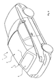
- the convertible vehicle 1 shown in FIG. 8 has a convertible top 2 which is connected to a rear window 3 is provided, which is bordered by a frame area 4 is.
- the device 6 comprises a support 7 for the frame area 4 comprising Part 5 of the top 2.
- the frame area 4 can complete or partial gripping of a disk 3 may be provided.
- the edition 7 can be designed so that the part 5 can be held completely on it, what in the case of a flexible part 5, for example, also by folding areas of part 5 is possible.
- the device 6 further comprises a fixing device, designated overall by 8 for precise alignment and mounting of the disc 3 in the device 6.
- the fixing device 8 comprises individual links 9, the act on the disc 3 and fix it in the processing position and can hold.
- the links 9 are in the exemplary embodiment as thrust links trained, which is not mandatory.
- the thrust members 9 are each received in scenes 10, which are essentially stand perpendicular to the edge 11 of the inserted disc 3 and one in predefined substantially at right angles to the pane edges 11 Condition the path of movement of the thrust members 9.
- at least one drive member 12 is provided, which via a rotating linkage 13 actuates several or all thrust members 9. The Movement of the thrust members 9 is therefore forcibly synchronized.
- FIG. 3 shows a linkage 13 connected at a coupling point 14, which can be actuated via two synchronized drive elements 12.
- a coupling point 14 which can be actuated via two synchronized drive elements 12.
- the coupling 14 a corresponding conclusion of the associated Linkage parts 13 allows.
- the rotating linkage 13 is via force-transmitting and fixed Pivots 15 pivotable lever 16 with the thrust members 9 moving Frame bodies 17 connected.
- the frame body 17 are during a pulling movement of the linkage 13 in the direction of arrow 18 by retracting the piston rods of the drive members 12 via the levers 16 and their pivoting about the axes of rotation 15 movable. Because the Push elements 9 on the one hand received in the frame bodies 17 and on the other hand are positively guided in the scenes 10, is only a movement of the Push elements 9 perpendicular to the extent of these scenes 10 is possible.
- the rotating linkage 13 ensures that all thrust members 9th are moved in the same way until all 3 with the disc inserted Push elements with the same force on the edge of the pane 11 Washer reaches its fixed end position, in which it uses a vacuum pump 20 can be held below the plane of the disk extension.
- the fixing device 8 is arranged overall on an assembly 21, between an open position (Fig. 1) and a closed position (Fig. 2) is mobile.
- the assembly 21 comprises two laterally hinged and support frames 22, 23 which can be swung open about horizontal axes and which are in the open position (Fig. 1) are essentially vertical and therefore access leave unimpaired for edition 7.
- the support frame 22, 23 can be motorized or manually operated via handles 24 in the closed position shown in FIG. 2.
- Fig. 4 is for connecting the top part 5 with the Pane 3 the frame area 4 of the pane overlapping the pane edge Convertible top part 5 received in a lower electrode 26 in such a way that the graduated shape of the electrode 26 a sewing or - Bonding of the frame area 4 is taken into account.
- the flipped Part of the frame area 4 is therefore stored such that both in the folded Area as well as in the adjoining single-layer area of the top part 5 the surface is at the same level, so that the thrust members 9 can shift in their trajectory without a gradation and the Disk 3 in its edge region 11 of a plane-engaging part of the convertible top.
- the gradation 27 is aligned parallel to the edge of the pane 11 and rotates the pane 3 in the entire frame area 4.
- the part 5, which comprises the frame area 4 is first inserted into the device 6 inserted, the assembly 21 is in the open position and thus the insertion is not hindered. Subsequently, the assembly 21 is closed, and the window, here rear window, 3 is put on. About the or the drive crane (s) 12 is exerted on the linkage parts by a force 13 such that arranged all around the inserted rear window 3 Push elements 9 are moved towards each other centrally and always in one same end position in which the disc 3 in from any direction the fixed end position has been moved. The trajectory of the Thrust members 9 extend parallel to the extent of the disc plane.
- FIGS. 6 and 7 The actual connection by in particular welding glue or others thermal connection method is two-stage and in FIGS. 6 and 7 shown: First, a disc 3 fixed and lowered in this way inner cover strip 29 placed on the edge area of the disc 3 in borders about the same width as the frame area 4. By lowering one also over this width region extending upper electrode 30 heat is brought into the connection zone for a defined period of time, whereby the welded or adhesive connection, for example also reactive Adhesive connection, is effected. Then the disk 3 can be fixed can be released by means of the push elements 9, these therefore move as in FIG. 7 is visible to the outside, thus freeing up an area in which the cover strip 29 freely above the outer layer of the frame area 4 Part 5 of the top 2 is located. By lowering the second electrode 31 can then (FIG. 7) heat input into an outside the pane edge 11 lying area are made in which the cover strip 29 and the outer layer of part 5 pressed together and connected become.
Landscapes
- Engineering & Computer Science (AREA)
- Mechanical Engineering (AREA)
- Window Of Vehicle (AREA)
- Automobile Manufacture Line, Endless Track Vehicle, Trailer (AREA)
- Securing Of Glass Panes Or The Like (AREA)
- Blinds (AREA)
- Sewing Machines And Sewing (AREA)
- Transition And Organic Metals Composition Catalysts For Addition Polymerization (AREA)
Abstract
Description
- Fig. 1
- die erfindungsgemäße Vorrichtung bei geöffneter Baugruppe und nach Einlegung des den Rahmenbereich umfassenden Teils des Verdecks in perspektivischer Ansicht,
- Fig. 2
- die Vorrichtung nach Fig. 1 nach Zuführung und Fixierung der Scheibe,
- Fig. 3
- eine Draufsicht auf die Vorrichtung in Stellung nach Fig. 2 mit gestrichelt eingezeichneten Antriebsgliedern für die Bewegung der Schubglieder,
- Fig. 4
- einen Schnitt entlang der Linie IV-IV in Fig. 3,
- Fig. 5
- eine ähnliche Ansicht wie Fig. 4 nach Unterdruckfestlegung,
- Fig. 6
- eine ähnliche Ansicht wie Fig. 5 während des Verschweißens bzw. Verklebens des Rahmenteils sowie des Abdeckstreifens mit der Scheibe,
- Fig. 7
- eine ähnliche Ansicht wie Fig. 6 während des Verschweißens bzw. Verklebens des Abdeckstreifens mit dem Teil des Verdecks, der den Rahmenbereich für die Heckscheibe umfaßt,
- Fig. 8
- ein Cabriolet-Fahrzeug mit einem nach dem erfindungsgemäßen Verfahren hergestellten Verdeck in perspektivischer Ansicht.
Claims (11)
- Vorrichtung (6) zur Herstellung eines Cabriolet-Verdecks (2), das einen Rahmenbereich (4) zum zumindest teilweisen Umgreifen einer Scheibe (3), insbesondere einer Heckscheibe, umfaßt, wobei in der Vorrichtung (6) ein den Rahmenbereich (4) umfassender Teil (5) des Verdecks (2) halterbar und mit der Scheibe (3) verbindbar ist, dadurch gekennzeichnet, daß die Vorrichtung (6) eine Fixierungseinrichtung (8) zur paßgenauen Halterung der Scheibe (3) bezüglich des Rahmenbereiches (4) umfaßt.
- Vorrichtung nach Anspruch 1, dadurch gekennzeichnet, daß die Fixierungseinrichtung (8) Schubglieder (9) umfaßt, die in der Ebene der eingelegten Scheibe (3) beweglich sind und über unterschiedliche Scheibenkanten (11) auf die Scheibe (3) einwirken können.
- Vorrichtung nach Anspruch 2, dadurch gekennzeichnet, daß die Schubglieder (9) miteinander gekoppelt verfahrbar sind und zur Fixierung der Scheibe (3) aus einer die Zuführung der Scheibe (3) ermöglichenden Öffnungsstellung in eine die zugeführte Scheibe (3) allseits einfassende Schließstellung verfahrbar sind.
- Vorrichtung nach einem der Ansprüche 1 bis 3, dadurch gekennzeichnet, daß die Schubglieder (9) in im wesentlichen rechtwinklig zum Scheibenrand stehenden Führungskulissen (10) aufgenomen sind.
- Vorrichtung nach einem der Ansprüche 1 bis 4, dadurch gekennzeichnet, daß die Schubglieder (9) an einer in Öffnungsstellung das Einlegen des Verdeckteils (5), das den Rahmenbereich (4) umfaßt, ermöglichenden Baugruppe (21) gehalten sind, die in Schließstellung das eingelegte Verdeckteil (5) im wesentlichen übergreift.
- Vorrichtung nach Anspruch 5, dadurch gekennzeichnet, daß die Baugruppe (21) zwei schwenkbare Tragrahmen (22;23) für Schubglieder (9) umfaßt.
- Vorrichtung nach Anspruch 6, dadurch gekennzeichnet, daß die Tragrahmen (22;23) für die Schubglieder (9) miteinander in Schließstellung koppelbar (14) sind und sämtliche Schubglieder (9) mittels eines Antriebsorgans (12) beweglich sind.
- Vorrichtung (6) zur Herstellung eines Cabriolet-Verdecks (2), das einen Rahmenbereich (4) zum zumindest teilweisen Umgreifen einer Scheibe (3), insbesondere einer Heckscheibe, umfaßt, wobei in der Vorrichtung (6) ein den Rahmenbereich (4) umfassender Teil (5) des Verdecks (2) halterbar und mit der Scheibe (3) verbindbar ist, dadurch gekennzeichnet, daß die Vorrichtung (6) eine an den Verlauf des Rahmenbereichs (4) angepaßte Elektrode (26) aufweist, die mit einer Abstufung (27) versehen ist.
- Vorrichtung nach Anspruch 8, dadurch gekennzeichnet, daß die Abstufung (27) über den gesamten dem Rahmenbereich (4) folgenden Verlauf der Elektrode (26) ausgebildet ist.
- Verfahren zur Verbindung eines einen Rahmenteil für eine Scheibe umfassenden Verdecks mit einer Scheibe, wobei die Scheibe zwischen dem den Rahmenbereich umfassenden Teil und einem Abdeckstreifen eingefaßt und mit beiden mittels Elektroden über Wärmeeinleitung verbunden wird, dadurch gekennzeichnet, daß in einem Schritt die Verbindung des den Rahmenbereich umfassenden Verdeckteils und des Abdeckstreifens mit der Scheibe und in einem anderen Schritt die Verbindung des Abdeckstreifens mit dem den Rahmenbereich umfassenden Teil des Verdecks durchgeführt wird.
- Verfahren nach Anspruch 10, dadurch gekennzeichnet, daß im ersten Schritt die Verbindung des Abdeckstreifens und des den Rahmenbereich umfassenden Teils des Verdecks mit der Scheibe durchgeführt werden, anschließend eine Fixierung der Scheibe über auf ihre Kanten einwirkende Mittel gelöst wird und in einem zweiten Schritt die Verbindung des Abdeckstreifens mit dem den Rahmenbereich umfassenden Teil des Verdecks durchgeführt wird.
Applications Claiming Priority (2)
| Application Number | Priority Date | Filing Date | Title |
|---|---|---|---|
| DE10109414A DE10109414B4 (de) | 2001-02-27 | 2001-02-27 | Herstellung eines Cabriolet-Verdecks |
| DE10109414 | 2001-02-27 |
Publications (3)
| Publication Number | Publication Date |
|---|---|
| EP1234699A2 true EP1234699A2 (de) | 2002-08-28 |
| EP1234699A3 EP1234699A3 (de) | 2003-06-11 |
| EP1234699B1 EP1234699B1 (de) | 2006-04-26 |
Family
ID=7675656
Family Applications (1)
| Application Number | Title | Priority Date | Filing Date |
|---|---|---|---|
| EP02001733A Expired - Lifetime EP1234699B1 (de) | 2001-02-27 | 2002-01-25 | Herstellung eines Cabriolet-Verdecks |
Country Status (4)
| Country | Link |
|---|---|
| US (1) | US6782603B2 (de) |
| EP (1) | EP1234699B1 (de) |
| AT (1) | ATE324285T1 (de) |
| DE (2) | DE10109414B4 (de) |
Families Citing this family (4)
| Publication number | Priority date | Publication date | Assignee | Title |
|---|---|---|---|---|
| DE10229939B3 (de) * | 2002-07-04 | 2004-03-11 | Wilhelm Karmann Gmbh | Herstellung von Cabriolet-Verdecken |
| JP2006232113A (ja) * | 2005-02-25 | 2006-09-07 | Toyo Seat Co Ltd | 車両用幌の幌布接合構造 |
| DE102006033368A1 (de) * | 2006-07-19 | 2008-01-24 | Wilhelm Karmann Gmbh | Verfahren zur Herstellung einer Verklebung und Fahrzeugdach mit textilem Verdeckstoff |
| US8707531B1 (en) | 2009-10-22 | 2014-04-29 | Western Digital Technologies, Inc. | Storage device assembly fixture |
Citations (1)
| Publication number | Priority date | Publication date | Assignee | Title |
|---|---|---|---|---|
| DE29817980U1 (de) | 1998-10-08 | 2000-02-17 | Wilhelm Karmann GmbH, 49084 Osnabrück | Heckscheibe und deren Befestigung am Verdeckbezug eines Cabriolet-Fahrzeugs |
Family Cites Families (9)
| Publication number | Priority date | Publication date | Assignee | Title |
|---|---|---|---|---|
| DE3841036A1 (de) * | 1988-12-06 | 1990-06-07 | Mehler Vario System Gmbh | Verfahren zum ersetzen einer fensterscheibe in einem flexiblen verdeck und austauschscheibe fuer dieses verfahren |
| DE8816696U1 (de) * | 1988-12-06 | 1990-05-03 | Mehler Vario System GmbH, 6400 Fulda | Lösbare Fensterbefestigung in einem flexiblen Klappverdeck eines Fahrzeuges |
| US5600922A (en) * | 1993-03-15 | 1997-02-11 | Mehler Vario System Gmbh | Construction for fastening a sheet of transparent plastic material in an opening of an awning |
| DE9306462U1 (de) * | 1993-04-29 | 1994-02-10 | Wilhelm Karmann GmbH, 49084 Osnabrück | Heckfensterscheibe für Cabriolet-Fahrzeuge |
| DE19642648C2 (de) * | 1996-10-16 | 1999-09-02 | Volkswagen Ag | Fahrzeugscheibenmodul und Verfahren zu dessen Herstellung |
| JP4010467B2 (ja) * | 1997-05-12 | 2007-11-21 | マツダ株式会社 | コンバーチブル・トップ組立体、並びにその製造方法、及び装置 |
| US6015181A (en) * | 1997-11-12 | 2000-01-18 | Exner; Anna L. | Flush fit removable backlight |
| DE19860555B4 (de) * | 1998-12-22 | 2009-11-12 | Daimlerchrysler Rail Systems Gmbh | Verfahren und Montagevorrichtung zur positionsgenauen Montage von Fahrzeugfenstern |
| DE19914801C1 (de) * | 1999-04-01 | 2000-07-06 | Parat Automotive Schoenenbach | Verfahren und Formwerkzeug zum Anbringen eines Gießharz-Wulstelements an ein Verdeckelement oder zum Verbinden zweier Verdeckelemente mit einem Gießharz-Wulstelement sowie Verdeck für ein Fahrzeug |
-
2001
- 2001-02-27 DE DE10109414A patent/DE10109414B4/de not_active Expired - Fee Related
-
2002
- 2002-01-25 EP EP02001733A patent/EP1234699B1/de not_active Expired - Lifetime
- 2002-01-25 AT AT02001733T patent/ATE324285T1/de not_active IP Right Cessation
- 2002-01-25 DE DE50206512T patent/DE50206512D1/de not_active Expired - Lifetime
- 2002-02-06 US US10/072,723 patent/US6782603B2/en not_active Expired - Fee Related
Patent Citations (1)
| Publication number | Priority date | Publication date | Assignee | Title |
|---|---|---|---|---|
| DE29817980U1 (de) | 1998-10-08 | 2000-02-17 | Wilhelm Karmann GmbH, 49084 Osnabrück | Heckscheibe und deren Befestigung am Verdeckbezug eines Cabriolet-Fahrzeugs |
Also Published As
| Publication number | Publication date |
|---|---|
| DE10109414A1 (de) | 2002-09-12 |
| ATE324285T1 (de) | 2006-05-15 |
| US20020116806A1 (en) | 2002-08-29 |
| EP1234699B1 (de) | 2006-04-26 |
| DE10109414B4 (de) | 2004-10-21 |
| DE50206512D1 (de) | 2006-06-01 |
| EP1234699A3 (de) | 2003-06-11 |
| US6782603B2 (en) | 2004-08-31 |
Similar Documents
| Publication | Publication Date | Title |
|---|---|---|
| EP0811518B2 (de) | Fahrzeug, insbesondere mit einem einklappbarem Dach | |
| DE68910038T2 (de) | Flexibler Verdeckmechanismus eines Fahrzeuges. | |
| DE102012106545A1 (de) | Verstellvorrichtung für einen Dachdeckel eines öffnungsfähigen Fahrzeugdachs | |
| EP1849634B1 (de) | Vorrichtung und Verfahren zur Montage eines Fahrzeugfensters | |
| DE60029760T2 (de) | Verfahren und Vorrichtung zum Biegen von Laminatmaterial | |
| DE3311599A1 (de) | Tuer eines motofahrzeuges und verfahren zum montieren der tuer | |
| CH649128A5 (de) | Vorrichtung zur herstellung von eckverbindungen von abdichtungsprofilen fuer fenster, tueren oder dergleichen. | |
| DE69002871T2 (de) | Mischer mit beweglichem Schutzschirm. | |
| EP0387557A2 (de) | Schiebedach und/oder Schiebehebedach für Fahrzeuge | |
| EP0885713B1 (de) | Vorrichtung zum gleichzeitigen Verschweissen von mindestens vier auf Gehrung geschnittenen Profilabschnitten | |
| EP1298272A2 (de) | Laufwagenanordnung eines Beschlags für Hebe-Schiebe-Türen oder -Fenster sowie Beschlag mit einer solchen Laufwagenanordnung | |
| DE2128717A1 (de) | Verfahren und Vorrichtung zur Herstellung einer Isolierverglasung | |
| DE2624061C3 (de) | An einem zu öffnenden Fahrzeugkabinenfenster angebrachte Scheibenwischeranlage | |
| DE3129900A1 (de) | Schiebehebedach fuer kraftfahrzeuge | |
| EP3222407A1 (de) | Schweissautomat | |
| EP1234699A2 (de) | Herstellung eines Cabriolet-Verdecks | |
| DE8809487U1 (de) | Stapelschneider | |
| EP4015406B9 (de) | Einrichtung und verfahren zum einbringen einer öffnung in einen teilbereich einer folienumhüllung eines, vorzugsweise auf einer palette angeordneten, gutstapels, wobei die folienumhüllung vorzugsweise als über den gutstapel gezogene folienhaube oder als den gutstapel zumindest teilweise umgebende folienbanderole ausgebildet ist | |
| DE19747480C1 (de) | Maschine zum Schneiden und Schweißen von Kunststoffplatten | |
| DD283573A5 (de) | Vorrichtung zur montage der teile eines winkeltriebes | |
| DE19817056C2 (de) | Fahrzeug-Dachaufbau sowie Verfahren zur Montage eines Moduldachs | |
| DE20122230U1 (de) | Herstellung eines Cabriolet-Verdecks | |
| CH617982A5 (en) | Door-control device with a rocker arm | |
| DE3004479C2 (de) | Verfahren bei der Herstellung von Fensterrahmen mit Glashalteleisten aus Holz und Vorrichtung zur Durchführung des Verfahrens | |
| DE2617934C2 (de) | Vorrichtung zum Be- und Entlüften von sowie zum Abzug von Rauch und Wärme aus Räumen |
Legal Events
| Date | Code | Title | Description |
|---|---|---|---|
| PUAI | Public reference made under article 153(3) epc to a published international application that has entered the european phase |
Free format text: ORIGINAL CODE: 0009012 |
|
| AK | Designated contracting states |
Kind code of ref document: A2 Designated state(s): AT BE CH CY DE DK ES FI FR GB GR IE IT LI LU MC NL PT SE TR |
|
| AX | Request for extension of the european patent |
Free format text: AL;LT;LV;MK;RO;SI |
|
| PUAL | Search report despatched |
Free format text: ORIGINAL CODE: 0009013 |
|
| AK | Designated contracting states |
Designated state(s): AT BE CH CY DE DK ES FI FR GB GR IE IT LI LU MC NL PT SE TR |
|
| AX | Request for extension of the european patent |
Extension state: AL LT LV MK RO SI |
|
| 17P | Request for examination filed |
Effective date: 20030710 |
|
| 17Q | First examination report despatched |
Effective date: 20030930 |
|
| AKX | Designation fees paid |
Designated state(s): AT BE CH CY DE DK ES FI FR GB GR IE IT LI LU MC NL PT SE TR |
|
| GRAP | Despatch of communication of intention to grant a patent |
Free format text: ORIGINAL CODE: EPIDOSNIGR1 |
|
| GRAS | Grant fee paid |
Free format text: ORIGINAL CODE: EPIDOSNIGR3 |
|
| GRAA | (expected) grant |
Free format text: ORIGINAL CODE: 0009210 |
|
| AK | Designated contracting states |
Kind code of ref document: B1 Designated state(s): AT BE CH CY DE DK ES FI FR GB GR IE IT LI LU MC NL PT SE TR |
|
| PG25 | Lapsed in a contracting state [announced via postgrant information from national office to epo] |
Ref country code: IT Free format text: LAPSE BECAUSE OF FAILURE TO SUBMIT A TRANSLATION OF THE DESCRIPTION OR TO PAY THE FEE WITHIN THE PRESCRIBED TIME-LIMIT;WARNING: LAPSES OF ITALIAN PATENTS WITH EFFECTIVE DATE BEFORE 2007 MAY HAVE OCCURRED AT ANY TIME BEFORE 2007. THE CORRECT EFFECTIVE DATE MAY BE DIFFERENT FROM THE ONE RECORDED. Effective date: 20060426 Ref country code: NL Free format text: LAPSE BECAUSE OF FAILURE TO SUBMIT A TRANSLATION OF THE DESCRIPTION OR TO PAY THE FEE WITHIN THE PRESCRIBED TIME-LIMIT Effective date: 20060426 Ref country code: IE Free format text: LAPSE BECAUSE OF FAILURE TO SUBMIT A TRANSLATION OF THE DESCRIPTION OR TO PAY THE FEE WITHIN THE PRESCRIBED TIME-LIMIT Effective date: 20060426 Ref country code: FI Free format text: LAPSE BECAUSE OF FAILURE TO SUBMIT A TRANSLATION OF THE DESCRIPTION OR TO PAY THE FEE WITHIN THE PRESCRIBED TIME-LIMIT Effective date: 20060426 |
|
| REG | Reference to a national code |
Ref country code: GB Ref legal event code: FG4D Free format text: NOT ENGLISH |
|
| REG | Reference to a national code |
Ref country code: IE Ref legal event code: FG4D Free format text: LANGUAGE OF EP DOCUMENT: GERMAN |
|
| REF | Corresponds to: |
Ref document number: 50206512 Country of ref document: DE Date of ref document: 20060601 Kind code of ref document: P |
|
| PG25 | Lapsed in a contracting state [announced via postgrant information from national office to epo] |
Ref country code: SE Free format text: LAPSE BECAUSE OF FAILURE TO SUBMIT A TRANSLATION OF THE DESCRIPTION OR TO PAY THE FEE WITHIN THE PRESCRIBED TIME-LIMIT Effective date: 20060726 Ref country code: DK Free format text: LAPSE BECAUSE OF FAILURE TO SUBMIT A TRANSLATION OF THE DESCRIPTION OR TO PAY THE FEE WITHIN THE PRESCRIBED TIME-LIMIT Effective date: 20060726 |
|
| PG25 | Lapsed in a contracting state [announced via postgrant information from national office to epo] |
Ref country code: ES Free format text: LAPSE BECAUSE OF FAILURE TO SUBMIT A TRANSLATION OF THE DESCRIPTION OR TO PAY THE FEE WITHIN THE PRESCRIBED TIME-LIMIT Effective date: 20060806 |
|
| GBT | Gb: translation of ep patent filed (gb section 77(6)(a)/1977) |
Effective date: 20060821 |
|
| PG25 | Lapsed in a contracting state [announced via postgrant information from national office to epo] |
Ref country code: PT Free format text: LAPSE BECAUSE OF FAILURE TO SUBMIT A TRANSLATION OF THE DESCRIPTION OR TO PAY THE FEE WITHIN THE PRESCRIBED TIME-LIMIT Effective date: 20060926 |
|
| NLV1 | Nl: lapsed or annulled due to failure to fulfill the requirements of art. 29p and 29m of the patents act | ||
| REG | Reference to a national code |
Ref country code: IE Ref legal event code: FD4D |
|
| PGFP | Annual fee paid to national office [announced via postgrant information from national office to epo] |
Ref country code: MC Payment date: 20061212 Year of fee payment: 6 |
|
| ET | Fr: translation filed | ||
| PGFP | Annual fee paid to national office [announced via postgrant information from national office to epo] |
Ref country code: AT Payment date: 20070111 Year of fee payment: 6 |
|
| PGFP | Annual fee paid to national office [announced via postgrant information from national office to epo] |
Ref country code: LU Payment date: 20070125 Year of fee payment: 6 |
|
| PGFP | Annual fee paid to national office [announced via postgrant information from national office to epo] |
Ref country code: CH Payment date: 20070129 Year of fee payment: 6 |
|
| PLBE | No opposition filed within time limit |
Free format text: ORIGINAL CODE: 0009261 |
|
| STAA | Information on the status of an ep patent application or granted ep patent |
Free format text: STATUS: NO OPPOSITION FILED WITHIN TIME LIMIT |
|
| PGFP | Annual fee paid to national office [announced via postgrant information from national office to epo] |
Ref country code: BE Payment date: 20070322 Year of fee payment: 6 |
|
| 26N | No opposition filed |
Effective date: 20070129 |
|
| PG25 | Lapsed in a contracting state [announced via postgrant information from national office to epo] |
Ref country code: GR Free format text: LAPSE BECAUSE OF FAILURE TO SUBMIT A TRANSLATION OF THE DESCRIPTION OR TO PAY THE FEE WITHIN THE PRESCRIBED TIME-LIMIT Effective date: 20060727 |
|
| BERE | Be: lapsed |
Owner name: WILHELM KARMANN G.M.B.H. Effective date: 20080131 |
|
| PG25 | Lapsed in a contracting state [announced via postgrant information from national office to epo] |
Ref country code: MC Free format text: LAPSE BECAUSE OF NON-PAYMENT OF DUE FEES Effective date: 20080131 |
|
| REG | Reference to a national code |
Ref country code: CH Ref legal event code: PL |
|
| PG25 | Lapsed in a contracting state [announced via postgrant information from national office to epo] |
Ref country code: LI Free format text: LAPSE BECAUSE OF NON-PAYMENT OF DUE FEES Effective date: 20080131 Ref country code: CH Free format text: LAPSE BECAUSE OF NON-PAYMENT OF DUE FEES Effective date: 20080131 |
|
| PG25 | Lapsed in a contracting state [announced via postgrant information from national office to epo] |
Ref country code: AT Free format text: LAPSE BECAUSE OF NON-PAYMENT OF DUE FEES Effective date: 20080125 |
|
| PG25 | Lapsed in a contracting state [announced via postgrant information from national office to epo] |
Ref country code: BE Free format text: LAPSE BECAUSE OF NON-PAYMENT OF DUE FEES Effective date: 20080131 |
|
| PG25 | Lapsed in a contracting state [announced via postgrant information from national office to epo] |
Ref country code: CY Free format text: LAPSE BECAUSE OF FAILURE TO SUBMIT A TRANSLATION OF THE DESCRIPTION OR TO PAY THE FEE WITHIN THE PRESCRIBED TIME-LIMIT Effective date: 20060426 |
|
| PG25 | Lapsed in a contracting state [announced via postgrant information from national office to epo] |
Ref country code: TR Free format text: LAPSE BECAUSE OF FAILURE TO SUBMIT A TRANSLATION OF THE DESCRIPTION OR TO PAY THE FEE WITHIN THE PRESCRIBED TIME-LIMIT Effective date: 20060426 |
|
| PG25 | Lapsed in a contracting state [announced via postgrant information from national office to epo] |
Ref country code: LU Free format text: LAPSE BECAUSE OF NON-PAYMENT OF DUE FEES Effective date: 20080125 |
|
| REG | Reference to a national code |
Ref country code: DE Ref legal event code: R119 Ref document number: 50206512 Country of ref document: DE Ref country code: DE Ref legal event code: R409 Ref document number: 50206512 Country of ref document: DE |
|
| PGFP | Annual fee paid to national office [announced via postgrant information from national office to epo] |
Ref country code: IT Payment date: 20110429 Year of fee payment: 10 |
|
| REG | Reference to a national code |
Ref country code: DE Ref legal event code: R409 Ref document number: 50206512 Country of ref document: DE |
|
| PG25 | Lapsed in a contracting state [announced via postgrant information from national office to epo] |
Ref country code: IT Free format text: LAPSE BECAUSE OF NON-PAYMENT OF DUE FEES Effective date: 20120125 |
|
| PGFP | Annual fee paid to national office [announced via postgrant information from national office to epo] |
Ref country code: GB Payment date: 20130122 Year of fee payment: 12 Ref country code: FR Payment date: 20130207 Year of fee payment: 12 |
|
| REG | Reference to a national code |
Ref country code: GB Ref legal event code: 732E Free format text: REGISTERED BETWEEN 20131114 AND 20131120 |
|
| REG | Reference to a national code |
Ref country code: FR Ref legal event code: TP Owner name: VALMET AUTOMOTIVE OY, FI Effective date: 20131209 |
|
| REG | Reference to a national code |
Ref country code: DE Ref legal event code: R082 Ref document number: 50206512 Country of ref document: DE Representative=s name: KRONTHALER, SCHMIDT & COLL. PATENTANWALTSKANZL, DE Effective date: 20131128 Ref country code: DE Ref legal event code: R081 Ref document number: 50206512 Country of ref document: DE Owner name: VALMET AUTOMOTIVE OY, FI Free format text: FORMER OWNER: WILHELM KARMANN GMBH, 49084 OSNABRUECK, DE Effective date: 20131128 |
|
| PGFP | Annual fee paid to national office [announced via postgrant information from national office to epo] |
Ref country code: DE Payment date: 20140220 Year of fee payment: 13 |
|
| GBPC | Gb: european patent ceased through non-payment of renewal fee |
Effective date: 20140125 |
|
| REG | Reference to a national code |
Ref country code: FR Ref legal event code: ST Effective date: 20140930 |
|
| PG25 | Lapsed in a contracting state [announced via postgrant information from national office to epo] |
Ref country code: FR Free format text: LAPSE BECAUSE OF NON-PAYMENT OF DUE FEES Effective date: 20140131 Ref country code: GB Free format text: LAPSE BECAUSE OF NON-PAYMENT OF DUE FEES Effective date: 20140125 |
|
| REG | Reference to a national code |
Ref country code: DE Ref legal event code: R119 Ref document number: 50206512 Country of ref document: DE |
|
| PG25 | Lapsed in a contracting state [announced via postgrant information from national office to epo] |
Ref country code: DE Free format text: LAPSE BECAUSE OF NON-PAYMENT OF DUE FEES Effective date: 20150801 |